Table of Contents
Advertisement
Available languages
Available languages
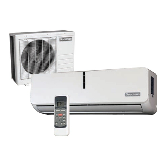
INSTALLATION & OPERATIONS MANUAL
SPLIT TYPE ROOM AIR CONDITIONER AND HEAT PUMP MODELS
MSC/MSH 15 SEER 12,000 BTUH & 18,000 BTUH • 230/208 VOLT
MSC/MSH 19 SEER 12,000 BTUH & 18,000 BTUH • 230/208 VOLT
O
Important Safety Instructions
The following symbols and labels are used throughout this
manual to indicate immediate or potential safety hazards. It is
the owner's and installer's responsibility to read and comply
with all safety information and instructions accompanying these
symbols. Failure to heed safety information increases the risk
of personal injury, property damage, and/or product damage.
HIGH VOLTAGE!
Disconnect ALL power before servicing.
Multiple power sources may be present.
Failure to do so may cause property damage,
personal injury or death.
Goodman will not be responsible for any injury or
property damage arising from improper service or
service procedures. If you perform service on your
own product, you assume responsibility for any
personal injury or property damage which may result.
IO-412A
April 2013
15 SEER
© 2011, 2013 Goodman Manufacturing Company, L.P.
5151 San Felipe, Suite 500, Houston, TX 77056
www.goodmanmfg.com -or- www.amana-hac.com
O
OUTDOOR UNIT
To prevent the risk of property damage, personal injury, or
death, do not store combustible materials or use gasoline
or other flammable liquids or vapors in the vicinity of this
appliance.
To prevent heat related illness or death, do not use this
device for unattended cooling of persons or animals unable
to react to product failure. Failure of unattended air
conditioner may result in extreme heat in area intended
for cooling, causing heat-related illness or death of
persons or animals.
To prevent the risk of property damage or personal injury,
keep hands and foreign objects away from outlet port and
intake grille while the unit is in operation.
Shipping Inspection
Always keep the unit upright; laying the unit on its side or top
may cause equipment damage. Shipping damage, and subse-
quent investigation is the responsibility of the carrier. Verify
the model number, specifications, electrical characteristics,
and accessories are correct prior to installation. The distribu-
tor or manufacturer will not accept claims from dealers for trans-
portation damage or installation of incorrectly shipped units.
19 SEER
Advertisement
Chapters
Table of Contents

Related Manuals for Goodman MSC 15 Series


Summary of Contents for Goodman MSC 15 Series
-
Page 1: Important Safety Instructions
To prevent the risk of property damage or personal injury, keep hands and foreign objects away from outlet port and intake grille while the unit is in operation. Goodman will not be responsible for any injury or property damage arising from improper service or Shipping Inspection service procedures. -
Page 2: Table Of Contents
CONTENTS • Select a location where there are no obstructions in front or the sides of the unit. Important Safety Instructions ..........1 Shipping Inspection ............1 • Be sure that placement of the unit allows adequate con- Codes & Regulations ............2 densate drainage. -
Page 3: Rooftop Installations
• Do not place animals or plants in the path of the air inlet or outlet. • Select a location where noise, vibration and hot dis- charged air will not be an issue. • Do not install where high frequency equipment is used (wireless equipment, welding machine, medical facility) as it may interfere with the unit’s operation. - Page 4 3. Install the mounting bracket on the wall with eight (8) 19 SEER MODELS type “A” screws. NOTE: Install the mounting bracket and drill the holes in the wall according to the wall structure and the correspond- ing mounting points on the mounting bracket. (The mounting brackets vary according to the model.) Incorrect orientation Correct orientation...
-
Page 5: Outdoor Unit Installation
7. REFRIGERANT PIPING INSTALLATION:: For the left- Piping and wrapping hand and right-hand piping, remove the pipe cover from Evenly bundle the tubing, connecting cable and drain hose the side panel. (Figure 8.) securely with tape as shown in Figure 12. Because the condensed water from the rear of the indoor unit gathers in the drain pan and is piped out of the room, do not put anything else in the drain pan. - Page 6 Drain joint installation NOTE: Drain joints differ slightly according to the different outdoor units. Inspect your unit and use the installation in- structions for your specific unit. For drain joints with seals (Figure 15A): • Slide the seal onto the drain joint and insert into the base pan hole of the outdoor unit.
-
Page 7: Refrigerant Pipe Connection
Refrigerant Pipe Connection A (inches & mm) Outdoor Diameter NOTE: The main cause of refrigerant leaks is due to defective (Inches & mm) flare connections. 1/4" (6.35) 3/64" (1.3) 1/32" (0.7) Make flare connections using the following procedure: 3/8" ( 9.52) 1/16"... -
Page 8: Electrical
• All wiring must comply with local and national electrical codes. Installation should be done by qualified electri- cians. To avoid the risk of personal injury, wiring to the unit must be properly polarized and grounded. Figure 21 • This unit should have a individual branch circuit . NOTE: The wire gauge and the current rating of the fuse or breaker are determined by the minimum circuit ampacity and Do not over-tighten. -
Page 9: Connect The Cable To The Outdoor Unit
4. Ensure the color of the wires of the outdoor unit and the 2. Remove caps on the conduit panel. terminal numbers are the same as the indoor unit’s. Fig- 3. Temporarily mount the conduit tubes (not included) on ure 22B. the conduit panel. -
Page 10: Leak Testing (Nitrogen Or Nitrogen-Traced)
2. Evacuate the system to 250 microns or less using suc- IMPORTANT NOTES: tion AND liquid service valves. Using both valves is nec- After the above conditions have been met, ensure the following essary as some compressor create a mechanical seal notes are met: separating the sides of the system. -
Page 11: Safe Refrigerant Handling
Safe Refrigerant Handling While these items will not cover every conceivable situation, they should serve as a useful guide. WARNING Refrigerants are heavier than air. They can "push out" the oxygen in your lungs or in any enclosed space.To avoid possible difficulty in breathing or death: •... - Page 12 The unit will operate under forced AUTO or COOL mode (see User’s manual for more details.) Figure 25 4. Test operation should last approximately 30 minutes. Goodman Manufacturing Company, L.P. 5151 San Felipe, Suite 500, Houston, TX 77056 www.goodmanmfg.com © 2011, 2013 Goodman Manufacturing Company, L.P.
- Page 13 De votre propre proDUit voUS aSSUmez la reSponSabilité De toUte bleSSUre perSonnelle oU De toUt Dommage matériel qUi poUrrait SUrvenir © 2011, 2013 Goodman Manufacturing Company, L.P. ◊ 5151 San Felipe, Suite 500 ◊ Houston, Texas 77056 IO-412A www.goodmanmfg.com...
-
Page 14: Inspection De Livraison
• N'exposez pas l'unité à une chaleur excessive. vertIssement • Choisissez un endroit où il n'y a pas d'obstructions en face ou sur les côtés de l'unité. oUr éviter le riSqUe De DommageS matérielS De bleSSUreS oU De DécèS entrepoSez paS De matériaUx combUStibleS et n UtiliSez paS D eSSence oU D... -
Page 15: Installations Sur Toiture
nstallatIons sur toIture S'il s'avère nécessaire d'installer l'unité extérieure sur une toiture, assurez-vous que la structure de cette dernière puisse en supporter le poids et qu'une attention particulière soit prêtée à l'intégrité de l'étanchéité du toit. Étant donné que l'unité peut vibrer pendant son fonctionnement, les transmissions de vibrations sonores doivent être prises en compte lors de l'installation de l'unité. - Page 16 nstallatIon des tuyauterIes du réfrIgérant et du condensat rientation correcte rientation incorrecte INSTALLATION ’ ’ De la plaqUe D inStallation De la plaqUe D inStallation 5. Le tuyau d'évacuation doit être installé avec une légère inclinai- son vers le bas. (Voir Figure 6). xtérieUr ntérieUr Figure 4...
-
Page 17: Installation De L'unité Intérieure
Pour effectuer des connexions de tube de réfrigérant, reportez- nstallatIon de l unIté extérIeure vous à Serrer les connexions de de la section de connexion de Précautions d'installation extérieure raccordement du réfrigérant. • Installez l'unité extérieure sur une base rigide pour réduire le niveau sonore et les vibrations. -
Page 18: Connexion Des Conduites De Réfrigérant
imenSionS De l Unité extérieUre imenSionS De montage oDèle l2 ( l1 ( oUceS 31 po. x 21 po. x 10 po. 21,5 po. 11 po. MS*12*E15 780 x 540 x 250 30 po. x 23 po. x 11 po. 21 po. -
Page 19: Branchements Électriques
poUceS et mm ttentIon iamètre extérieUr poUceS et mm e Serrez paS trop fort n coUple exceSSif peUt caSSer l écroU et oU gaUfrer le tUyaU 1/4 po. (6,35) 3/64 po. (1,3) 1/32 po. (0,7) 3/8 po. ( 9,52) 1/16 po. (1,6) 3/64 po. -
Page 20: Connexion Du Câble À L'unité Extérieure
Figure 23B Remarque : Le serre-câble doit être d'une taille adéquate pour prévenir le relâchement ou le glissement des câbles du serre-câble. Sélectionnez Figure 22A le diamètre de câble adéquat pour remplir les orifices du serre-câble. 2. Retirez les capuchons du panneau de conduits. 4. -
Page 21: Test De Fuite (Azote Ou Traces D'azote)
5. Reliez l'unité au sol conformément aux codes locaux. Longueur 6. Veillez à avoir une taille de câble adéquate et à prévoir quelques de la Méthode Quantité supplémentaire Modèle conduite de d'évaluation de réfrig. à charger centimètres supplémentaires à la longueur requise pour le connexion câblage de l'unité. -
Page 22: Contrôles De Sécurité
ffectuer des tests Après avoir contrôlé la présence éventuelle de fuite de gaz au niveau des raccords d'écrou d'évasement et vérifié la sécurité électrique, effectuez un fonctionnement de test. • Veillez à ce que tous les tubes et les câbles aient été correctement branchés. - Page 23 emarques IO-412A www.goodmanmfg.com...
- Page 24 emarques www.goodmanmfg.com IO-412A...
- Page 25 A su ProDucto Asume lA resPonsAbiliDAD Por cuAlquier lesión PersonAl o DAños mAteriAles que PueDAn ProDucirse como resultADo © 2011, 2013 Goodman Manufacturing Company, L.P. ◊ 5151 San Felipe, Suite 500 ◊ Houston, Texas 77056 IO-412A www.goodmanmfg.com...
-
Page 26: Inspección De Envío
• No la exponga al calor excesivo. dvertencIa • Elija una ubicación en la que no haya obstrucciones delante o a los lados de la unidad. ArA imPeDir el riesgo De DAños mAteriAles lesiones PersonAles o lA muerte no AlmAcene mAteriAles combustibles ni use gAsolinA u otros líquiDos o vAPores inflAmAbles en lA ProximiDAD De este ArtefActo •... -
Page 27: Instalaciones En Azoteas
nstalacIones en azoteas Si es necesario instalar la unidad exterior en una estructura sobre el techo, asegúrese de que éste pueda soportar el peso y de que se considere en forma apropiada la integridad a prueba de intemperie. Como la unidad puede vibrar durante su funcionamiento, debería considerarse la transmisión de vibración del sonido. - Page 28 nstalacIón de tuberías de refrIgerante y condensacIón rientAción correctA De lA rientAción incorrectA De lA nStalaCión PlAcA De instAlAción PlAcA De instAlAción 5. La manguera de drenaje debería instalarse con una ligera pendiente hacia abajo (vea la figura 6). igUra 4.
-
Page 29: Instalación De Unidad Interior
Para conectar las tuberías del refrigerante, consulte Ajuste de la conexión nstalacIón de unIdad exterIor en Conexión de la tubería del refrigerante. reCaUCioneS en la inStalaCión exterior • Instale la unidad exterior en una base rígida para impedir ruido y nstalacIón de unIdad InterIor vibración. -
Page 30: Conexiones Del Conducto De Refrigerante
Dimensiones de la unidad Dimensiones de montaje exterior Modelo Pulgadas/ mm (largo 1 x largo 2 largo 1 alto x ancho 1) (mm) (mm) 31 pulgadas x 21 pulgadas x 21.5 pulgadas 11 pulgadas MS*12*E15 10 pulgadas 780 x 540 x 250 30 pulgadas x 23 pulgadas x 21 pulgadas 11.5 pulgadas... -
Page 31: Sistema Eléctrico
A (pulgadas y mm) recaucIón Diámetro exterior (pulgadas y mm) Máx. Mín. o Ajuste De más A torsión excesivA PueDe romPer lA tuercA o PellizcAr lA tuberíA 1/4 pulgadas (6.35) 3/64 pulgadas (1.3) 1/32 pulgadas (0.7) 3/8 pulgadas (9.52) 1/16 pulgadas (1.6) 3/64 pulgadas (1.0) 1/2 pulgadas (12.7) 1/16 pulgadas (1.8) -
Page 32: Conecte El Cable A La Unidad Exterior
igUra Nota: la abrazadera debe ser del tamaño correcto para impedir que los cables se suelten o se deslicen de ella. Elija el diámetro apropiado igUra de cables para llenar los orificios en la abrazadera. 2. Retire las tapas del panel de conducto. 3. -
Page 33: Prueba De Fugas (Nitrógeno O Indicios De Nitrógeno)
5. Conecte a tierra la unidad de acuerdo con los códigos locales. ongitUd de étodo de antidad adiCional de odelo 6. Asegúrese de medir cada cable y dejar varias pulgadas extra de la tUBería ConeCtora evalUaCión reFrig a Ser Cargada longitud requerida al cablear la unidad. -
Page 34: Control De Seguridad
ealIzacIón de pruebas Luego de terminar el control de fuga de gas en las conexiones de tuerca abocardada y el control de seguridad eléctrica, realice el funcionamiento de prueba. • Asegúrese de que las tuberías y los cables se hayan conectado en forma apropiada. - Page 35 otas IO-412A www.goodmanmfg.com...
- Page 36 otas www.goodmanmfg.com IO-412A...
Need help?
Do you have a question about the MSC 15 Series and is the answer not in the manual?
Questions and answers
Unfamiliar code on my condo unit where the temperature is usually displayed
Need control board MSC183E15MC