Table of Contents
Advertisement
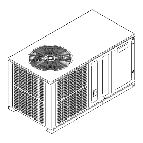
INSTALLATION & OPERATING
INSTRUCTIONS FOR
SELF CONTAINED PACKAGE
AIR CONDITIONERS AND
HEAT PUMPS
GPC/GPH SERIES
All information contained herein is subject to change without notice.
Goodman Manufacturing Company, L.P.
IO-313
2550 North Loop West, Suite 400, Houston, TX 77092
06/06
www.goodmanmfg.com
www.amana-hac.com
© 2005-2006 Goodman Manufacturing Company, L.P.
Advertisement
Table of Contents

Related Manuals for Goodman GPC SERIES


Summary of Contents for Goodman GPC SERIES
- Page 1 INSTALLATION & OPERATING INSTRUCTIONS FOR SELF CONTAINED PACKAGE AIR CONDITIONERS AND HEAT PUMPS GPC/GPH SERIES All information contained herein is subject to change without notice. Goodman Manufacturing Company, L.P. IO-313 2550 North Loop West, Suite 400, Houston, TX 77092 06/06 www.goodmanmfg.com www.amana-hac.com ©...
-
Page 2: Table Of Contents
INDEX ADJUSTING SPEED TAP FOR INDOOR BLOWER MOTOR ............10 INTRODUCTION ............2 CHECKING CHARGE ..........10 Checking Product Received ......... 2 ELECTRIC HEAT INSTALLATION & ADJUSTMENT... 11 Message to the Homeowner ........2 Before Beginning Installation ........2 MAINTENANCE ............11 Service ................ -
Page 3: Mportant Safety Instructions
IMPORTANT SAFETY INSTRUCTIONS phase units in this series are not covered under the DOE certified program. The efficiency ratings of these units are a Recognize Safety Symbols, Words, and Labels product of thermal efficiency determined under continuous The following symbols and labels are used throughout this operating conditions independent of any installed system. -
Page 4: Location
compressor compartment and controls. The top of the unit Rooftop Installation (Figure 2) should be completely unobstructed. If units are to be located Before locating the unit on the roof, make sure that the under an overhang, there should be a minimum of 36” strength of the roof and beams is adequate to support the clearance and provisions made to deflect the warm discharge weight involved. -
Page 5: Plenum Application
Connecting the Return and Supply Flexible Duct in Plenum Application Manufactured or Modular Housing Application A suitable plenum or square duct must be constructed. The The return and supply fittings are to be attached at the unit duct cross-sectional area should be determined by industry to a suitable square to round duct converter. -
Page 6: High Voltage Wiring
Heat Pumps- Connect 24V wires from the thermostat to All units have undergone a run test prior to packaging for the corresponding wires in the control box using No. shipment. This equipment has been started at minimum 18AWG as follows: rated voltage and checked for satisfactory operation. -
Page 7: Heat Pump Start-Up Procedure
Turn the fan switch to the “ON” position. The blower should 15. If checking the unit in the wintertime, when the outdoor coil is cold enough to actuate the defrost control, observe at operate after a 7 second delay. least one defrost cycle to make sure the unit defrosts Turn the fan switch to “Auto”... -
Page 8: Indoor Blower Motor
Indoor Blower Motor EXPLANATION AND GUIDANCE (HEAT PUMP) This item is activated by the room thermostat The heat pump is a relatively simple device. It operates by COOLING/HEATING or FAN ON position. The motor is exactly as a Summer Air Conditioner unit when it is on the energized through the EBTDR for PSC motors. -
Page 9: Defrost Control
When the solenoid valve coil is operated either from heating TEST to cooling or vice versa, the piston in the reversing valve to the low pressure (high pressure) reverse positions in the JUMPER WIRE reversing valve. The following figures show a schematic of a heat pump on W2 R R DFT the cooling cycle and the heating cycle. -
Page 10: Adjusting Speed Tap For Indoor Blower Motor
ADJUSTING SPEED TAP FOR INDOOR BLOWER MOTOR Saturated Suction Suction Pressure PSC Motor Temperature (°F) Adjust the CFM for the unit by changing the speed tap of the indoor blower motor at the EBTDR “com” connection with one of the speed taps on “M1” or “M2”. (Black-High Speed, Blue-Medium Speed, Red-Low Speed.) X-13 Motor The blower motor speed for the X-13 motor is controlled... -
Page 11: Electric Heat Installation & Adjustment
SUPERHEAT CAN BE DETERMINED AS FOLLOWS: Common Causes of Unsatisfactory Operation of Heat Pump on the Heating Cycle. Read suction pressure. Determine Saturated Suction Temperature from tables or pressure gauge saturated Inadequate Air Volume Through Indoor Coil temperature scale (R-22). When a heat pump is in the heating cycle, the indoor coil is Read suction line temperature. -
Page 12: Troubleshooting Chart
TROUBLESHOOTING CHART DISCONNECT ALL POWER TO UNIT BEFORE SERVICING. FAILURE TO FOLLOW THIS WARNING WARNING MAY RESULT IN PERSONAL INJURY OR DEATH DUE TO ELECTRICAL SHOCK. POSSIBLE CAUSE REMEDY SYMPTOM High head - low suction a. Restriction in liquid line or flowrator a.
Need help?
Do you have a question about the GPC SERIES and is the answer not in the manual?
Questions and answers