EcoWater ERO-375 User Manual
Undersink reverse osmosis drinking water system
Hide thumbs
Also See for ERO-375:
- Owner's manual (28 pages) ,
- Installation, operation and maintenance manual (27 pages)
Table of Contents
Advertisement
Undersink
REVERSE OSMOSIS
DRINKING WATER SYSTEM
ERO-375
HERO-375
Safety Guides
Installation
Operation
Maintenance
Repair Parts
System tested and certified by NSF International
EcoWater Systems LLC
against NSF/ANSI Standard 58.
See performance data sheet for details.
P.O. Box 64420
St. Paul, MN 55164
TEL (651) 739-5330
7300493 (Rev. D 9/17/08)
Advertisement
Table of Contents

Subscribe to Our Youtube Channel
Related Manuals for EcoWater ERO-375


Summary of Contents for EcoWater ERO-375
- Page 1 Safety Guides Installation Operation Maintenance Repair Parts System tested and certified by NSF International EcoWater Systems LLC against NSF/ANSI Standard 58. See performance data sheet for details. P.O. Box 64420 St. Paul, MN 55164 TEL (651) 739-5330 7300493 (Rev. D 9/17/08)
-
Page 2: Table Of Contents
1, 3, 5 and 10 YEAR EcoWater Systems LLC, guarantees to the original owner that:for a period of ten (10) years from from the date of pur- chase, the RO holding tank will be free from defects in material and workmanship. All other parts of the drinking water system will be guaranteed for a period of five (5) years from defects in material and workmanship. -
Page 3: Safety Guides
DO NOT install the Drinking Water System outside, or in Changes or modifications not expressly approved by extreme hot or cold temperatures. Temperature of the water EcoWater Systems could void the user’s authority to operate supply to the Drinking Water System must be between 40°F the equipment. -
Page 4: Specifications
SPECIFICATIONS Feed water pressure limits - pounds per square inch (psi)........40 - 100 Feed water temperature limits - minimum / maximum degrees F . -
Page 5: What The Drinking Water System Will Do
/or local codes. Optional fittings are avail- (drilling required), or a special drain adapter are available able from EcoWater for use in areas where codes permit. from EcoWater to use where codes permit. Refer to Pages 24 and 27. These options install on the sink drain pipe THINGS TO CHECK BEFORE YOU START TO tailpiece, above the p-trap. -
Page 6: Installing
INSTALLATION - FEED WATER SUPPLY Check and comply with local plumbing codes as you FIGURE 1 plan, then install a cold feed (supply) water fitting. The fitting must provide a leak tight connection to the RO 1/4" OD tubing, see Figure 6, Page 10. A typical installa- tion, using standard plumbing fittings is shown in Figure 1. -
Page 7: Installing Faucet
Slide the large steel washer in Page 10. place, between the bushing (or spacer) and the bottom 2. For Model ERO-375, slide the chrome washer onto of the sink or countertop. Then, tighten the hex nut the faucet stud, Figure 3. -
Page 8: Installing Ro Assembly & Storage Tank
INSTALL RO ASSEMBLY AND STORAGE TANK 1. Hold the RO assembly up to the wall surface FIGURE 5 NOTE: Be sure to allow a minimum space of 4" above the system for where you will install it. Mark locations for the hanger removing the top cover to change washers and screws. -
Page 9: Tubing Connections
TUBING CONNECTIONS HOW TO CUT AND CONNECT THE TUBES Remove and Discard Foam Plugs Your Reverse Osmosis Water System includes push-in push-in fitting fittings for quick tubing connection. Review the follow- foam plug ing instructions before connecting the tubes in the next step. -
Page 10: Drain Tubing
CONNECT WATER SUPPLY, STORAGE TANK AND DRAIN TUBING 1. Connect faucet drain tubing (if using p-trap 2. Install Flow Control Insert: Before connecting the drain): Run the 3/8" black tubing from the 3/8" faucet 1/4” red tubing to the RO system manifold’s drain port, barb, to the drain fitting installed on page 6. -
Page 11: Sanitizing / Pressure Testing / Purging
SANITIZING THE RO SYSTEM SANITIZE THE SYSTEM mon household bleach (5.25%). 4. Add 3 mL. of bleach into open end of yellow tank Sanitizing is recommended immediately after installa- tion of the Reverse Osmosis system. It’s also recom- tubing. Handle bleach according to bleach manufactur- mended after servicing inner parts. -
Page 12: Installing Hydrolink™ Ro Module
INSTALL THE HYDROLINK™ RO MODULE (Model HERO-375 Only) WIRING CONNECTIONS Wire from faucet. FIGURE 7 Plug into 1. Locate the cable packed with the Hydrolink™ RO receptacle Hydrolink™ Module. One end should be plugged into the tele- RO Module Plugged into phone-style receptacle identified by the RO icon: receptacle 2. -
Page 13: Connecting Hydrolink™ Ro Module To Remote
CONNECT THE HYDROLINK™ RO MODULE TO THE REMOTE (Model HERO-375 Only) NOTE: If you do not have a Hydrolink™-equipped FIGURE 10 CONNECT button water conditioner (with remote), skip this procedure. (push with ball point pen) The RO electronics and the indicator light on the faucet base will function normally, as described on Page 18. -
Page 14: How The Hydrolink™ Ro Module Works
AC powered devices. Up to 6 devices may be added to one remote, Replace filters (See Page 19 for filter replacement including no more than 3 EcoWater Systems 3500 series instructions) water softeners. An AC powered device with a trans-... -
Page 15: Status Led On The Hydrolink™ Ro Module
STATUS LED ON THE HYDROLINK™ RO MODULE (Model HERO-375 Only) The LED on the Hydrolink™ LED Indication Status RO Module indicates status of Not Flashing Batteries dead or RO electronics not detected the unit’s operations, as shown Short Flash every 15 seconds Normal operation in the table: Busy (normal at startup and when connecting... -
Page 16: Changing The Remote Display
CHANGING THE REMOTE DISPLAY (Model HERO-375 Only) CHANGING WHICH DATA ITEMS ARE DIS- NOTE: If you turn off all data items, there will still be a PLAYED IN THE STATUS SCREEN status screen for the HERO-375 on the remote, but it will be blank below the header. - Page 17 CHANGING THE REMOTE DISPLAY (Model HERO-375 Only) RENAMING A DEVICE DELETING A DEVICE “HERO-375” is the default name in the RO status To delete a device from the remote (possible reasons for screen on the remote. This name may be customized deleting a device include replacing or upgrading the (up to 20 characters long) as follows: Hydrolink™...
-
Page 18: How The Ro System Works
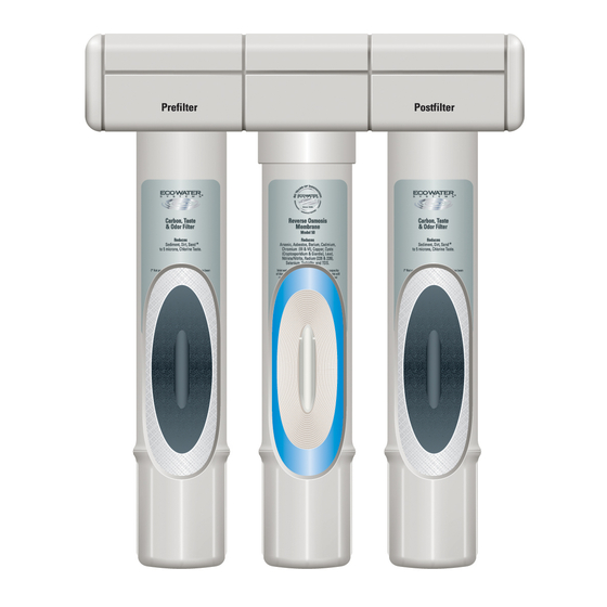
HOW THE RO SYSTEM WORKS PREFILTER When the batteries are first installed at initial start up, the LED indicator light will flash in a red, amber, green Water from the cold supply pipe enters the RO assem- sequence. All timers and counters are reset to zero. In bly sediment prefilter first. -
Page 19: Replacing The Filters & Ro Membrane
CARE OF YOUR REVERSE OSMOSIS SYSTEM To keep your reverse osmosis system operating and PREFILTER AND POST FILTER CARTRIDGES producing high quality water, you must make sure You must replace the prefilter cartridge often to protect supply water is always within the limits shown in the the RO membrane from being destroyed by chlorine, specifications. - Page 20 CARE OF YOUR REVERSE OSMOSIS SYSTEM continued from Page 19 AUTOMATIC SHUTOFF / PADDLEWHEEL SERVICE flashes or the production rate and/or quality of product water drops. Product water may begin to taste different If either the shutoff assembly or paddlewheel requires or bad, indicating solids and organics are passing service, be sure to reassemble parts exactly as shown through the RO membrane.
- Page 21 CARE OF YOUR REVERSE OSMOSIS SYSTEM FILTER CHANGE ALERT LED (HERO-375 only) The Model HERO-375 provides the option of alerting you to the need for a filter change at either 6 or 12 month intervals. The timer is factory set to 6 months. The recommended interval is 6 months, but certain water conditions may allow a 12 month setting.
-
Page 22: Troubleshooting
B. High Total Dissolved Solids (TDS) in Product Water: If water quality is in question, contact your local EcoWater dealer for testing. It is important to test both the treated and untreated water to determine system perform- ance. If the TDS is not within the system's performance guidelines, replace the prefilter, post filter and RO membrane cartridges. -
Page 23: System Schematic
REVERSE OSMOSIS SCHEMATIC FIGURE 22 Water Flow Description 1. Water enters prefilter. Sand, silt and other sediments are reduced. Chlorine is also reduced. 2. Water leaves prefilter and proceeds to the Reverse Osmosis Cartridge. 3. Water enters the Reverse Osmosis membrane. Dissolved solids are reduced. 4. -
Page 24: Installation Of Optional Fittings
INSTALLATION OF OPTIONAL FITTINGS (not included) SADDLE VALVE, part no. 7011272 3. Install the drain adapter onto the sink tailpiece, using a ferrule and nut. Snug the nut, but do not tight- NOTE: This valve will pierce a hole in copper tubing or plastic pipe. -
Page 25: Remote Installation
REMOTE LOCATION FOR REVERSE OSMOSIS SYSTEM Possible remote locations for the RO nearby the kitchen You can run the drain tubing directly to one of several or bathroom sink include; suitable open drain points, as shown below, bypassing the faucet airgap and p-trap drain. This type of drain (1) a basement area underneath the sink, and is the preferred over the p-trap drain adapter. -
Page 26: Repair Parts
REPAIR PARTS Manifold Housing PUSH - IN FITTINGS o-ring seal collet... - Page 27 This o-ring and collet are for replacement in the manifold To order parts call your local EcoWater dealer or go to housing only. They do not fit the other push-in fittings, key www.ecowater.com to locate a dealer in your area.
Need help?
Do you have a question about the ERO-375 and is the answer not in the manual?
Questions and answers