Table of Contents
Advertisement
Quick Links
371
WELLS MANUFACTURING COMPANY
2 ERIK CIRCLE, P. O. Box 280
Verdi, NV 89439
Customer Service (775) 345-0444 Ext.502
fax: (775) 345-0569
www.wellsbloomfield.com
OPERATION
MANUAL
for
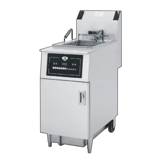
GAS FRYER
model
WFGA-60FS
includes:
Installation
Use and Care
IMPORTANT: DO NOT DISCARD THIS MANUAL
This manual is considered to be part of the FRYER and is to be given to the OWNER or
MANAGER of the restaurant, or to the person responsible for TRAINING OPERATORS
of the FRYER. Additional manuals are available from your WELLS DEALER .
THIS MANUAL MUST BE READ AND UNDERSTOOD BY ALL PERSONS USING OR
INSTALLING THIS FRYER. Contact your WELLS DEALER if you have any questions
concerning installation, operation or maintenance of this equipment.
Part. No 301098 Rev. A
M371 012100 cps
Advertisement
Table of Contents

Subscribe to Our Youtube Channel
Related Manuals for Wells WFGA-60FS


Summary of Contents for Wells WFGA-60FS
-
Page 1: Use And Care
This manual is considered to be part of the FRYER and is to be given to the OWNER or MANAGER of the restaurant, or to the person responsible for TRAINING OPERATORS of the FRYER. Additional manuals are available from your WELLS DEALER . THIS MANUAL MUST BE READ AND UNDERSTOOD BY ALL PERSONS USING OR INSTALLING THIS FRYER. -
Page 2: Shipping Damage Claim Procedure
Be sure to retain the container for inspection. Wells Manufacturing cannot assume liability for damage or loss incurred in transit. We will, however, at your request, supply you with the necessary documents to support your claim. -
Page 3: Table Of Contents
TABLE OF CONTENTS Warranty Inside Cover Specifications Features and Operating Controls Safety Procedures Installation Instructions Operating Instructions - Solid State Controller * Maintenance Instruction Cradle Lift Assembly Lubrication Cradle Roller Assembly Filter Leaf Assembly Filtering Oil Discarding Used Oil Cleaning the Fryer * Troubleshooting Service Parts List * TO BE PERFORMED BY QUALIFIED PERSONEL ONLY... -
Page 4: Features And Operating Controls
WFGA-60FS w/SOLID STATE CONTROLLER FEATURES and OPERATING CONTROLS FRONT VIEW BACK VIEW UPPER CONTROL PANEL FRYER TIME TEMP HEAT READY MANUAL FILTER MANUAL PAUSE CLEAN STANDBY BASKET FILTER LOWER CONTROL PANEL HI-LIMIT RESET POWER SWITCH FRYER position turns ON the FRYER and energizes the UPPER (FRYER-OFF-FILTER) CONTROL PANEL;... - Page 5 FIRE HAZARD / HOT OIL THE HI-LIMIT THERMOSTAT IS A FIRE PROTECTION DEVICE. If tripping persists, contact your authorized Wells service agency for repairs. DO NOT ATTEMPT TO BYPASS OR HOLD IN THE BUTTON OF THE HI-LIMIT THERMOSTAT. A FIRE WILL RESULT.
-
Page 6: Safety Procedures
WARNINGS MUST BE READ AND UNDERSTOOD BY ALL OPERATORS AND USERS. Your WELLS fryer is equipped with an oil filtration system, which is designed to filter hot liquid shortening ONLY. Water, cleaning agents or other liquids will damage the FILTER PUMP. -
Page 7: Installation Instructions
INSTALLATION INSTRUCTIONS UNPACKING AND INSPECTION 1. Carefully remove the FRYER from the carton. Remove all blue protective plastic film, packaging materials and accessories from the FRYER and the FILTER RESERVOIR before connecting electrical power to the FRYER or otherwise performing any installation procedures. NOTE: DO NOT discard the CARTON and other PACKAGING MATERIAL until you have inspected the fryer for hidden damage and tested it for PROPER OPERATION. - Page 8 EQUIPMENT SET-UP A single WFGA-60FS gas-fired fryer requires a minimum of 700 cubic feet per hour (12 CFM) make-up air. The ventilation for the kitchen must have sufficient capacity to prevent a negative-pressure condition. DO NOT obstruct or restrict ventilation and make-up air required to support combustion.
- Page 9 This fryer is orificed at the factory for natural gas at a pressure of 3.5” of water column. The installed orifice is suitable for use at -280 to 2999 feet (-85 to 914 meters) elevation. It is the responsibility of the installer to install the factory recommended orifice and pressure regulator kit suitable for the fuel type and elevation at the final installation site.
- Page 10 EQUIPMENT PREPARATION PRIOR TO OPERATION CLEANING: Prior to leaving the factory, the fryer is tested for proper operation with peanut oil. After testing is complete, the oil is removed but oil residue remains. Therefore, it is necessary t o cl ean t he f r ypot before filling it with clean oil. See CLEANING THE FRYER, page 21. 2.
- Page 11 5. Close the OVAL DRAIN VALVE HANDLE (item 19) by turning the handle to the CLOSED position. CLOSED OPEN NOTE: This fryer is designed for LIQUID SHORTENING ONLY. DO NOT USE SOLID SHORTENING OR LARD. Solid shortening will solidify in the filter reservoir and filter pump.
-
Page 12: Operating Instructions - Solid State Controller
OPERATING INSTRUCTIONS WFGA-60FS with SOLID STATE CONTROLLER NOTE: This fryer is equipped with two separate auto-ignition burner control systems. On startup, each ignition system will try three times to prove its associated burner flame. Failure to prove flame will result in shut-down of that burner circuit. Pressing the POWER SWITCH to OFF, then back to FRYER will reset the fryer (and make three more tries). - Page 13 Hint: MENU key 7 is unprogrammed so that special or one-of-a-kind product may be MANUAL programmed any time. With the fryer ON, press and hold the TIME key and MENU 7 key at the same time. Press the UP or DOWN arrow key until the desired time is displayed. If this MANUAL feature is not desired, MENU key 7 may be programmed in the identical fashion to MENU keys 1 thru 6.
- Page 14 USING THE FUNCTION KEYS (Item 8) Halts the time countdown while any menu is running and time remaining is displayed PAUSE on the readout. Purpose: Allows the user to raise the basket to inspect the product in the middle of a cook cycle.
- Page 15 PRE-HEAT THE FRYER Press a MENU key. If the oil temperature has not reached the programmed temperature, the readout will display “ ” ” “ followed by the menu key #, and the HEAT indicator will light. When the oil has reached the progammed temperature, the READY indicator will light, a “...
-
Page 16: Maintenance Instruction
MAINTENANCE INSTRUCTIONS CRADLE LIFT ASSEMBLY LUBRICATION PINCH HAZARD DISCONNECT THE FRYER FROM ELECTRICAL POWER BEFORE LUBRICATING THE CRADLE LIFT DRIVE SCREW. Failure to disconnect power may allow the lift motor to start unexpectedly, causing serious injury. CRADLE LIFT DRIVE SCREW GREASE THREADS ACCESS... -
Page 17: Cradle Roller Assembly
CRADLE ROLLER ASSEMBLIES SLIPPING & FALLING HAZARD / SPILLED OIL DO NOT USE CRADLE IF THE ROLLERS DO NOT SPIN FREELY. REPLACE ROLLERS IMMEDIATELY IF THEY ARE FROZEN. Oil spills may occur. Death or serious injury may result from falls caused by slipping in oil 1. - Page 18 DANGER BURN HAZARD / HOT OIL SPLATTER DO NOT REMOVE FILTER RESERVOIR WHEN IT CONTAINS HOT OIL. Contact with hot oil can cause death or serious injury. PROTECTIVE CLOTHING AND GLOVES MUST BE WORN DURING THE FILTERING PROCESS. BURN HAZARD DO NOT REMOVE EMPTY FILTER RESERVOIR IF IT IS HOT.
-
Page 19: Filtering Oil
THE FILTERING PROCESS. Hot oil may splatter, which could result in serious injury. NOTE: Your Wells fryer filtration system is designed to filter hot liquid shortening ONLY. Water, cleaning agents or other liquids will damage the FILTER PUMP. DO NOT attempt to filter cold oil(less than 300ºF/149ºC). - Page 20 BURN HAZARD PROTECTIVE CLOTHING AND INSULATED GLOVES MUST BE WORN WHEN CLEANING THE KETTLE WITH THE HI-TEMP BRUSH AND WHEN UNCLOGGING THE DRAIN WITH THE WOOD CLEANOUT DOWEL. The kettle will be hot and hot oil may splatter. Serious injury may result. 4.
-
Page 21: Discarding Used Oil
IMPORTANT NOTE: The following instructions for discarding used oil from the fryer may be disregarded if you use a WELLS MOBILE CADDY WAOC-1 (part no. 22470). The WAOC-1 is a manual oil pump/removal system which allows you to hand pump the used oil directly into the caddy, and to then hand pump the used oil into your oil disposal container by simply reversing the pump rotation. - Page 22 DISCARDING USED OIL WITHOUT USING THE WELLS MOBILE OIL CADDY 1. Press the POWER SWITCH to the OFF position and allow the oil to cool to 120ºF (49ºC), or less, before attempting to drain the oil from the fryer. All oil should be in the kettle Make sure all oil has been returned to kettle, and there is no oil remaining in the filter reservoir.
-
Page 23: Cleaning The Fryer
CLEANING THE FRYER CLEANING THE KETTLE: HOT BOIL-OUT METHOD SLIPPING & FALLING HAZARD / SPILLED OIL DO NOT STORE OIL IN THE FILTER RESERVOIR WHILE CLEANING THE KETTLE. IF CLEANING FLUID IS ACCIDENTALLY DRAINED INTO THE FILTER RESERVOIR, OIL WILL SPILL ON THE FLOOR. - Page 24 NOTE: When using a metal container, allow the solution to cool to below 120ºF for safe handling. Always safely dispose of used cleaning solution as required by local ordinances. 7. Rinse the kettle thoroughly with warm, clean water. Drain into the same container as used to dispose of the cleaning solution.
-
Page 25: Troubleshooting
HI-LIMIT THERMOSTAT. A FIRE MAY RESULT. 4. If: DISPLAY (item 4) LIT, HEAT indicator (item 3) lit & HI-LIMIT THERMOSTAT not tripped: Probable cause is misadjustment or a damaged internal component. Contact a Wells Mfg. Authorized Service Agency for repairs. - Page 26 2. Verify that gas pressure regulators are adjusted to recommended pressure (must be performed by a qualified technician). 3. Damaged or mis-adjusted internal component(s). Contact a Wells Mfg. Authorized Service Agency for repairs. PROBLEM: CRADLE LIFT WILL NOT LOWER or CRADLE LIFT WILL NOT RAISE 1.
- Page 27 PROBLEM: OIL NOT RETURNING TO FRYPOT DURING FILTER CYCLE CAUTION: BURN HAZARD / HOT OIL SPLASH / SPLATTER PROTECTIVE CLOTHING AND GLOVES MUST BE WORN WHENEVER SERVICING THE FILTER DURING THE FILTERING CYCLE Hot oil may splatter, which could result in serious injury. The surface of the FILTER LEAF may become clogged with crumbs or other debris.
-
Page 28: Service Parts List
2 Erik Circle, P. O. Box 280 Verdi, NV 89439 phone: (775) 345-0444 Ext.504 fax: (888) 492-2783 Service Parts Department can supply you with the name / telephone number of the WELLS AUTHORIZED SERVICE AGENCY nearest you. FRYER ACCESSORIES PART#... -
Page 29: Customer Service Data
NOTES CUSTOMER SERVICE DATA please have this information available if calling for service RESTAURANT _____________________________ LOCATION _______________ INSTALLATION DATE ________________________ TECHNICIAN _____________ SERVICE COMPANY __________________________________________________ ADDRESS ___________________________ STATE ______ ZIP__________ TELEPHONE NUMBER (_____)_____-_________ EQUIPMENT MODEL NO. ______________________________________________ EQUIPMENT SERIAL NO. ______________________________________________ VOLTAGE: (check one) 120V 208V... - Page 30 WELLS MANUFACTURING COMPANY 2 ERIK CIRCLE, P. O. Box 280 Verdi, NV 89439 Customer Service (775) 345-0444 Ext. 502 fax: (775) 345-0569 www.wellsbloomfield.com...
Need help?
Do you have a question about the WFGA-60FS and is the answer not in the manual?
Questions and answers