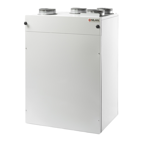
Summary of Contents for nilan Comfort CT300
- Page 1 Installation instruction CTS 700 by Nilan Comfort CT300 Comfort CT300 Polar Version: 1.00, 01-01-2015 Software version 1.40.05...
-
Page 2: Table Of Contents
Figure 2: Mounting the Comfort unit....................5 Figure 3: Installation of water trap ....................7 Figure 4: Insulation of ducting ......................8 Figure 5: Connecting the heating surface, suggestion ..............9 Figure 6: Filter change ........................13 Figure 7: System dimensions for Comfort CT300 ................. 14... -
Page 3: Introduction
Directions for assembly & use (this document) CTS 700 user guide Electrical chart Should you have any questions on how to operate the system, contact your nearest Nilan dealer, www.nilan.dk/dealers who you can find at The purpose of this instruction manual is to offer the installation contractor and the user instruc- tions on correct installation and maintenance of the Comfort system. -
Page 4: Power Supply
If a water heating element is installed in the system, the regulation vent must be connected electri- cally as described in the enclosed wiring diagrams. Page 4 af 15 Nilan reserves the right to alter these instructions without prior notice... -
Page 5: Assembly Of Comfort
When mounting the Comfort-unit future service and maintenance should be considered. For the Comfort CT300 a free place of minimum 60 cm in front of the system and 20 cm below the system is recommended. The CT300 can be mounted directly on the wall. -
Page 6: Condensation Drain / Water Seal
An elevated height of the water seal will reduce the need for refilling with water. Ø 20 mm drain 5 cm Unit 5 cm 11,5 cm Page 6 af 15 Nilan reserves the right to alter these instructions without prior notice... - Page 7 Fill the condensate tray with water and start the unit on the highest fan speed. Let the system run for a few minutes. Make sure that there is no water in the condensate tray when the test is completed. Page 7 af 15 Nilan reserves the right to alter these instructions without prior notice...
-
Page 8: Ducting
Page 8 af 15 Nilan reserves the right to alter these instructions without prior notice... -
Page 9: Heating Surface, Water
Connecting the heating surface must be done by an authorized plumber. Heating surface for Comfort CT300 is a surface that should be installed in the ducting. The heating unit is delivered as accessory and consists of heating surface with temperature sensor T9 and frost-protection B3, actuator and regulating valve. -
Page 10: Technical Specifications, Heating Surface, Water
Technical specifications, heating surface, water Connections: 15mm Cu-pipes for flow and return. Maximum output for Comfort CT300 is 2,0kW at a waterflow of 0,09m /h, a pressure drop of1,9kPa at the waterside and a flow temperature of 60°C. Pressure tested to13,5Bar.. -
Page 11: Heating Surface, Electrical (Retrofitting)
CTS 700 control panel as described on page 15. Power supply must be installed by an authorized electrician. See electrical chart for the ventilation unit. Page 11 af 15 Nilan reserves the right to alter these instructions without prior notice... -
Page 12: Heating Surface, Electrical (Retrofitting)
Heating coil must be equipped with temperature limiter and safety thermostat. Intet Unit 230 V Signal for overheatning The heating surface must be activated in the CTS 700 control panel. Page 12 af 15 Nilan reserves the right to alter these instructions without prior notice... -
Page 13: Filter Change Comfort Ct300
Before filter change the system is turned off. Screws are loosened and the lid is removed. The fil- ters can be removed without using tools. Figure 6: Filter change Page 13 af 15 Nilan reserves the right to alter these instructions without prior notice... -
Page 14: System Dimensions
System dimensions Figure 7: System dimensions for Comfort CT300 Page 14 af 15 Nilan reserves the right to alter these instructions without prior notice... -
Page 15: Accessories/Spare Parts
Pollen filter for fitting Comfort CT 300 3987 Pollen filter for fitting Comfort CT 300 3885 Filter G4 (1set = 2stk.) Comfort CT 300 3939001 Page 15 af 15 Nilan reserves the right to alter these instructions without prior notice...


Need help?
Do you have a question about the Comfort CT300 and is the answer not in the manual?
Questions and answers