Table of Contents
Advertisement
Advertisement
Table of Contents

Subscribe to Our Youtube Channel
Related Manuals for Mercury motorguide X5-55


Summary of Contents for Mercury motorguide X5-55
- Page 1 Operation Maintenance Installation Warranty Manual...
- Page 3 EU Compliance Statement Attwood Corporation hereby declares that the MotorGuide X5 trolling motor is in compliance with the essential requirements and other relevant provisions of the 99/5/EC R&TTE directive. CE Declaration Manufacturer: Attwood Corporation Address: 1016 N. Monroe Lowell, MI 49415 USA Telephone: 616‑897‑9241 Authorized Representative: Brunswick Marine Parc Industriel de Petit‑Rechain...
- Page 4 MotorGuide, Lowell, Michigan U.S.A. Copyright and Trademark Information © MERCURY MARINE. All rights reserved. Reproduction in whole or in part without permission is prohibited. Alpha, Axius, Bravo One, Bravo Two, Bravo Three, Circle M with Waves Logo, K‑planes, Mariner, MerCathode, MerCruiser, Mercury, Mercury with Waves...
-
Page 5: Table Of Contents
Warranty Information MotorGuide Limited Two Year Warranty............1 General Information Boater's Responsibilities..................3 Protecting People in the Water................3 Passenger Safety Message................3 Safe Boating Suggestions.................. 3 Product Overview X5‑55/X5‑70/X5‑80/X5‑105 MotorGuide Trolling Motor........5 Specifications...................... 6 Wiring and Battery Information Wiring and Battery Information................ - Page 6 Inspection and Maintenance Schedule............. 25 Lubrication Points..................... 26 Battery Inspection..................... 26 Propeller Replacement..................27 Adjusting the Steering Cable Tension.............. 29 Front Locking Pin Replacement................ 30 MotorGuide Accessories Inquiries..............32 Troubleshooting Trolling Motor Performance................33 Owner Service Assistance Mercury Marine Service Offices................ 35...
-
Page 7: Warranty Information
MotorGuide products due to repairs performed by anyone other than the MotorGuide Factory Service Center. Neither MotorGuide nor Mercury Marine is responsible for failure or damage caused by improper installation, set‑up, preparation, or previous service or repair errors. - Page 8 3) use of an accessory or part not manufactured by MotorGuide/ Mercury; 4) alteration or removal of parts; 5) opening the lower unit (motor) by anyone other than the Factory Service Center will void this warranty.
-
Page 9: General Information
GENERAL INFORMATION Boater's Responsibilities The operator (driver) is responsible for the correct and safe operation of the boat and safety of its occupants and general public. It is strongly recommended that each operator (driver) read and understand this entire manual before operating the trolling motor. - Page 10 GENERAL INFORMATION Do not overload your boat. Most boats are rated and certified for maximum load (weight) capacities, refer to your boat capacity plate. If in doubt, contact your dealer or the boat's manufacturer. Perform safety checks and required maintenance. Follow a regular schedule and ensure all repairs are made properly.
-
Page 11: Product Overview
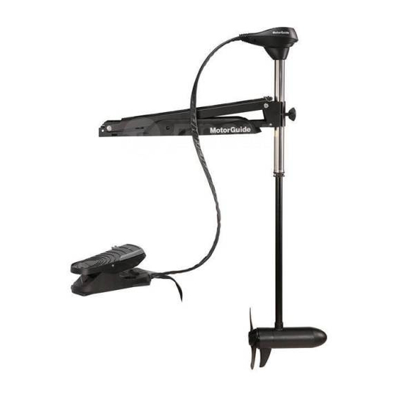
PRODUCT OVERVIEW X5‑55/X5‑70/X5‑80/X5‑105 MotorGuide Trolling Motor 58588 Directional indicator 53.3 cm (21 in.) mount bracket Latch release handle Foot pedal Momentary button 3‑position switch Speed control knob Battery cables 61 cm (24 in.) mount bracket (optional) Propeller Lower unit Composite column Bracket door knob... -
Page 12: Specifications
PRODUCT OVERVIEW Specifications Speeds Freshwater/ Peak Shaft Model Volts Forward/ Sonar Saltwater Thrust Length Reverse X5‑55 24.9 kgf 114.3 cm Freshwater 12 V Variable (55 lbf) (45 in.) X5‑55 24.9 kgf 114.3 cm Freshwater 12 V Variable (55 lbf) (45 in.) X5‑70 31.8 kgf 114.3 cm... -
Page 13: Wiring And Battery Information
WIRING AND BATTERY INFORMATION Wiring and Battery Information WARNING An operating or charging battery produces gas that can ignite and explode, spraying out sulfuric acid, which can cause severe burns. Ventilate the area around the battery and wear protective equipment when handling or servicing batteries. -
Page 14: Battery Precautions
WIRING AND BATTERY INFORMATION Recommended MotorGuide Accessory Description Part Number 50‑amp manual reset circuit breaker MM5870 60‑amp manual reset circuit breaker 8M0064076 Battery Precautions WARNING An operating or charging battery produces gas that can ignite and explode, spraying out sulfuric acid, which can cause severe burns. Ventilate the area around the battery and wear protective equipment when handling or servicing batteries. -
Page 15: Wire And Cable Routing
WIRING AND BATTERY INFORMATION ELECTROLYSIS Using the main engine battery as a power source for the trolling motor may cause electrolysis on metallic parts. If the motor and battery wiring are installed correctly and electrolysis issues continue, separate the trolling motor from any other boat electronics. -
Page 16: Battery Connection
WIRING AND BATTERY INFORMATION Battery Connection WARNING Before working around electrical system components, disconnect the battery cables from the battery to prevent injury or damage to the electrical system due to an accidental short circuit. CAUTION Disconnecting or connecting the battery cables in the incorrect order can cause injury from electrical shock or can damage the electrical system. - Page 17 WIRING AND BATTERY INFORMATION 6. Starting with the positive (+) lead, reconnect the battery cables to the engine starting battery. 44291 12-volt battery connection with common ground bond Power cables to trolling motor Manual reset circuit breaker Trolling motor battery Engine starting battery Power cables to engine Common ground (–) bond cable...
- Page 18 WIRING AND BATTERY INFORMATION 6. Starting with the positive (+) lead, reconnect the battery cables to the engine starting battery. BLACK Battery A Battery B 37824 24-volt battery connection Power cables to trolling motor Manual reset circuit breaker Jumper wire (not supplied) Negative (–) battery terminal IMPORTANT: Do not connect a common ground bond cable between 24‑volt and 12‑volt electrical circuits.
- Page 19 WIRING AND BATTERY INFORMATION 6. Connect the trolling motor negative (–) lead to the negative (–) terminal on battery A. 7. Starting with the positive (+) lead, reconnect the battery cables to the engine starting battery. Battery A Battery B Battery C 37825 36-volt battery connection...
-
Page 20: Trolling Motor Installation And Operation
TROLLING MOTOR INSTALLATION AND OPERATION Mount Bracket Installation 58592 X5 bow mount bracket Latch release handle Bracket door knob 1. Select an appropriate area on the deck of the boat to install the mount. Ensure that the forward mounting screws will not penetrate the hull. IMPORTANT: Choose an area on the boat deck that allows a 7.6 cm (3 in.) clearance between the bow of the boat and the column of the trolling motor. - Page 21 TROLLING MOTOR INSTALLATION AND OPERATION IMPORTANT: A minimum of four mounting bolts are required to mount the trolling motor to the boat. Spread the mounting bolts as far apart as practical for the most secure mounting. 58594 Mount bracket mounting holes (5 per side) 3.
-
Page 22: Permanent Foot Pedal Mounting (Optional)
TROLLING MOTOR INSTALLATION AND OPERATION 5. Install the stainless steel washers and nylon locknuts onto the mounting screws underneath the boat deck. Tighten them securely with a P3 screwdriver and a 7/16 in. wrench. IMPORTANT: If necessary, shim the rubber washers with 25 mm (1 in.) outside diameter stainless steel washers to create a level mounting surface. -
Page 23: Installing The Motor Into The Bow Mount
TROLLING MOTOR INSTALLATION AND OPERATION 4. Use four #8 x 2 in. stainless steel screws to secure the foot pedal to the boat deck. 54589 Installing the Motor into the Bow Mount 1. Turn the bracket door knob counterclockwise to loosen and open the bracket door. -
Page 24: Connecting The Sonar Display To The Trolling Motor
TROLLING MOTOR INSTALLATION AND OPERATION Connecting the Sonar Display to the Trolling Motor NOTE: This procedure applies only to models equipped with integrated sonar. This sonar display connection procedure applies to trolling motor models with internal sonar that offer built‑in 200/83 kHz sonar transducers compatible with ®... - Page 25 TROLLING MOTOR INSTALLATION AND OPERATION 3. Continue to pull the latch release handle to raise the lower unit onto the mount. Latch release handle 58612 IMPORTANT: Gently raise the trolling motor out of the water. Do not release the latch release handle until the lock pin is engaged. 4.
-
Page 26: Deploying The Trolling Motor
TROLLING MOTOR INSTALLATION AND OPERATION 5. Position the tie‑down strap over the composite column and through the buckle. Pull it tight, then secure the hook‑and‑loop backing together to secure the motor to the mount bracket. Tie‑down strap 58617 Deploying the Trolling Motor WARNING Rotating propellers can cause serious injury or death. -
Page 27: Adjusting The Motor Depth
TROLLING MOTOR INSTALLATION AND OPERATION IMPORTANT: Gently lower the trolling motor into the water. Do not release the latch release handle until the lock pin is engaged. Latch release handle 58612 5. Once the motor is in the deployed position, the lock pin will engage to secure the trolling motor. - Page 28 TROLLING MOTOR INSTALLATION AND OPERATION CABLE STEER MODELS Adjust the depth of the motor to improve trolling motor performance in various water depths and wave conditions. IMPORTANT: When adjusting the motor depth, ensure that the propeller blades are fully submerged 15–30 cm (6–12 in.) below the water surface to avoid ventilation.
-
Page 29: Directional Indicator-Cable Steer Models
TROLLING MOTOR INSTALLATION AND OPERATION Directional Indicator—Cable Steer Models The indicator provides directional information at a glance. 58610 Directional indicator Right turn ‑ toe down; motor steers boat to right (continue to press all the way down for reverse) Straight ahead ‑ foot pedal in middle Left turn ‑... -
Page 30: Speed Control-Cable Steer Models
TROLLING MOTOR INSTALLATION AND OPERATION Speed Control—Cable Steer Models DIGITAL VARIABLE SPEED MOTORS Foot operated motors are available with digital variable speed control. Control the speed of your motor by rolling the speed control knob with your hand or foot until you reach the desired speed. -
Page 31: Maintenance
MAINTENANCE Trolling Motor Care To keep your trolling motor in the best operating condition and retain its dependability, it is important that your trolling motor receive periodic inspections and maintenance. We urge you to keep it maintained properly to ensure the safety of you and your passengers. -
Page 32: Lubrication Points
15 minutes before going above 30% operation. Lubrication Points NOTE: Preferred lubricants can be obtained at any authorized MotorGuide or Mercury Marine service center. To reduce friction and quiet squeaks, lubricate the specified locations periodically with the following lubricants: •... -
Page 33: Propeller Replacement
MAINTENANCE IMPORTANT: Read the safety and maintenance instructions which accompany your battery. 1. Ensure that the battery is secured to the vessel. 2. Ensure that the battery cable terminals are clean, tight, and correctly installed. For installation instructions, refer to Battery Connection. 3. - Page 34 MAINTENANCE NOTE: If the propeller pin is bent, replace the propeller pin. 53442 57326 INSTALLING THE PROPELLER 1. Rotate the motor shaft to insert the propeller pin horizontally. Propeller pin 44664...
-
Page 35: Adjusting The Steering Cable Tension
MAINTENANCE 2. Install the propeller onto the motor shaft by engaging the propeller onto the propeller pin. 57326 3. Install the washer (or anode, for saltwater models) onto the propeller shaft, then install the propeller nut. Use a wrench or a socket and ratchet to tighten the propeller nut until it is snug, then tighten the nut another 1/4 turn. -
Page 36: Front Locking Pin Replacement
MAINTENANCE 1. Remove the foot pedal from the boat deck if it has been secured with screws. 2. Adjust the cable tension by turning the cable tension screw clockwise to increase tension, and counterclockwise to decrease tension. Adjust the cable tension screw to the specified torque value. Description lb‑in. - Page 37 MAINTENANCE IMPORTANT: Do not release the latch release handle until the new locking pin is installed, or internal damage to the mount will occur. Locking pin Lock 58757 3. Once the lock is aligned as shown, press the locking pin in the direction indicated, but do not remove it completely.
-
Page 38: Motorguide Accessories Inquiries
MAINTENANCE NOTE: The new locking pin will press out the old locking pin as it is installed. Alignment tabs 58760 7. Release the latch release handle and move the trolling motor to the stowed or deployed position as desired. MotorGuide Accessories Inquiries Refer to www.motorguide.com for factory authorized accessories for all MotorGuide trolling motors. -
Page 39: Troubleshooting
TROUBLESHOOTING Trolling Motor Performance Symptom Possible Cause Resolution Weak battery Refer to Wiring and Battery Loose or corroded battery Information. connections Propeller is loose, Refer to Maintenance. damaged, or off‑balance Wire gauge from the battery Loss of power Wiring or electrical to the trolling motor is connection faulty insufficient. - Page 40 TROUBLESHOOTING Symptom Possible Cause Resolution Hold one blade and lightly tap the opposite blade with a rubber mallet. Bent propeller pin Difficulty removing Use a putty knife on both propeller sides of the propeller to apply equal pressure. Bent armature shaft Refer to service center.
-
Page 41: Owner Service Assistance
+1 954 744 3500 Mercury Marine 11650 Interchange Circle North Miramar, FL 33025 +1 954 744 3535 U.S.A. Asia, Singapore, Japan Telephone +65 65466160 Brunswick Asia Pacific Group T/A Mercury Marine Singapore Pte Ltd 29 Loyang Drive +65 65467789 Singapore, 508944...
Need help?
Do you have a question about the motorguide X5-55 and is the answer not in the manual?
Questions and answers