Table of Contents
Advertisement
Available languages
Available languages
Quick Links
Advertisement
Table of Contents

Related Manuals for LanParty 790GX M2RS


Summary of Contents for LanParty 790GX M2RS
-
Page 1: System Board
System Board User’s Manual 935-JR79G1-000G 06600831E... -
Page 2: Fcc And Doc Statement On Class B
Copyright This publication contains information that is protected by copyright. No part of it may be reproduced in any form or by any means or used to make any transfor- mation/adaptation without the prior written permission from the copyright hold- ers. -
Page 3: Table Of Contents
Table of Contents About this Manual................Warranty....................Static Electricity Precaution..............Safety Measures..................About the Package................Before Using the System Board............System Board Layout................English..................... Français....................Deutsch....................Italiano....................Español....................Debug LED POST and Troubleshooting.......... -
Page 4: About This Manual
Introduction About this Manual An electronic file of this manual is included in the CD. To view the user’s manual in the CD, insert the CD into a CD-ROM drive. The autorun screen (Main Board Utility CD) will appear. Click the “TOOLS”... -
Page 5: Static Electricity Precaution
Introduction Static Electricity Precautions It is quite easy to inadvertently damage your PC, system board, components or devices even before installing them in your system unit. Static electrical discharge can damage computer components without causing any signs of physical damage. You must take extra care in handling them to ensure against electrostatic build-up. -
Page 6: About The Package
Introduction About the Package The system board package contains the following items. If any of these items are missing or damaged, please contact your dealer or sales representative for assistance. One system board One IDE cable One floppy cable Two Serial ATA data cables One power cable with 2 Serial ATA power connectors Smart connectors One I/O shield... -
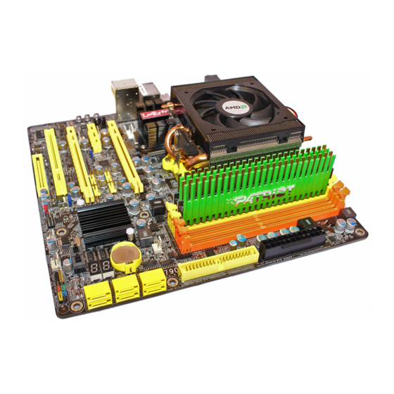
Page 7: System Board Layout
Introduction System Board Layout DDR2 -4 DDR2 -3 CPU fan DDR2 -1 DDR2 -2 Mouse PS/2 power select (J ) HDMI Coaxial RCA (top) / Optical (bottom) S/PDIF-out power 12V power HDMI/DVI select (JP15) USB 0-3 power select (J ) USB 0-1 USB 2-3 790GX... -
Page 8: English
English Chapter 1 - Introduction Specifications ® Processor • AMD AM2+ processors: Phenom FX / Phenom / Athlon / Sempron ® AM2 processors: Athlon series / Sempron • HyperTransport 3.0 (5200MT/s for AM2+) HyperTranspor t 1.0 (2000/1600MT/s for AM2) • AMD OverDrive provides tuning options using the new “Advanced Clock Calibration”... - Page 9 English • One IDE connector allows connecting up to two UltraDMA 133Mbps hard drives Serial ATA with • Supports up to 6 SATA devices RAID • SATA speed up to 3Gb/s • RAID 0, RAID 1 and RAID 0+1 Rear Panel I/O •...
-
Page 10: Jumper Settings
English Chapter 2 - Hardware Installation Jumper Settings Clear CMOS Data JP10 1-2 On: Normal 2-3 On: (default) Clear CMOS Data If you encounter the following, a) CMOS data becomes corrupted. b) You forgot the supervisor or user password. c) The overclocked settings in the BIOS resulted to the system’s in- stability or caused system boot up problems. - Page 11 English PS/2 Power Select 1-2 On: 5V 2-3 On: 5VSB (default) Important: The 5VSB power source of your power supply must suppor t ≥720mA. Selecting 5VSB will allow you to use the PS/2 keyboard or PS/2 mouse to wake up the system. USB Power Select USB 0-3 (JP5)
- Page 12 English HDMI/DVI Select JP15 A1-A2 to A2-A3 to H1-H2 On: H2-H3 On: HDMI The system board is equipped with HDMI and DVI interfaces but you can only connect one display device at a time. Set this jumper according to the type of display device connected to the system. PCIE Gen 1 / Gen 2 Select JP13 2-3 On: Gen 1...
- Page 13 English Rear Panel I/O Ports Center/ Subwoofer Rear R/L Coaxial PS/2 S/PDIF-out Line-in Mouse USB 1 Front R/L DVI-I Mic-in PS/2 K/B Optical USB 0 USB 2-3 Side R/L S/PDIF-out HDMI PS/2 Ports and S/PDIF Ports PS/2 Mouse PS/2 KB Coaxial RCA S/PDIF Optical S/PDIF...
- Page 14 English HDMI and DVI-I Ports HDMI DVI-I HDMI The HDMI port which carries both digital audio and video signals is used to connect a LCD monitor or digital TV that has the HDMI port. DVI-I The DVI-I port is used to connect a digital LCD monitor or LCD...
-
Page 15: Usb And Lan Ports
English USB and LAN Ports USB 1 USB 0 USB 3 USB 2 USB 6-7 USB 4-5 USB 10-11 USB 8-9 The USB ports are used to connect USB 2.0/1.1 devices. The 10-pin connectors allow you to connect 8 additional USB 2.0/1.1 ports. Your USB ports may come mounted on a card-edge bracket. - Page 16 English Audio and CD-In Rear audio Center/ Line-in Subwoofer Front R/L Rear R/L Mic-in Side R/L Front audio Right audio channel Ground CD-in Ground Left audio channel Rear Panel Audio Center/Subwoofer Jack (Orange) This jack is used to connect to the center and subwoofer speak- ers of the audio system.
-
Page 17: Serial Ata Connectors
English Mic-in Jack (Pink) This jack is used to connect an external microphone. Front Audio The front audio connector is used to connect to the line-out and mic-in jacks that are at the front panel of your system. CD-in The CD-in connector is used to receive audio from a CD-ROM drive, TV tuner or MPEG card. -
Page 18: Fdd Connector And Ide Connector
English FDD Connector and IDE Connector FDD Connector The floppy disk drive connector is used to connect a floppy drive. Insert one end of the floppy cable into this connector and the other end-most connector to the floppy drive. The colored edge of the cable should align with pin 1 of this connector. - Page 19 English IrDA,CIR and Serial (COM) Connectors IRRX N. C. Ground IRTX IrDA CIRRX N. C. 5VSB CIRTX IrDA and CIR Connect the cable connector from your IrDA module to the IrDA connector or CIR connector. Note: The sequence of the pin functions on some IrDA/CIR cable may be reversed from the pin function defined on the system board.
-
Page 20: Cooling Fan Connectors
English Cooling Fan Connectors Ground Speed Control Power Sense CPU fan Power Sense Ground Ground Sense Power Fan 6 Fan 2 Power Ground Sense Sense Ground Power Fan 5 Fan 3 Sense Ground Power Fan 4 These fan connectors are used to connect cooling fans. Cooling fans will provide adequate airflow throughout the chassis to prevent over- heating the CPU and system board components. - Page 21 English EZ Touch Switches Reset Power The presence of the power switch and reset switch on the system board are user-friendly especially to DIY users. They provide conven- ience in powering on and/or resetting the system while fine tuning the system board before it is installed into the system chassis.
- Page 22 English LEDs DRAM Power LED Diagnostic Standby Power LED DRAM Power LED This LED will light when the system’s power is on. Standby Power LED This LED will light when the system is in the standby mode. Diagnostic LED The Diagnostic LED displays POST codes. POST (Power-On Self Tests) which is controlled by the BIOS is performed whenever you power-on the system.
-
Page 23: Power Connectors
English Power Connectors Use a power supply that complies with the ATX12V Power Supply Design Guide Version 1.1. An ATX12V power supply unit has a standard 24-pin ATX main power connector that must be inserted into this connector. 1 2 2 4 +3.3VDC +12VDC +5VDC... - Page 24 English The power connectors from the power supply unit are designed to fit the 24-pin and 8-pin connectors in only one orientation. Make sure to find the proper orientation before plugging the connectors. The FDD-type power connector is an additional power connector. If you are using more than one graphics cards, we recommend that you plug a power cable from your power supply unit to the 5V/12V power connector.
- Page 25 English Restarting the PC Normally, you can power-off the PC by: 1. Pressing the power button at the front panel of the chassis. 2. Pressing the power switch that is on the system board (note: not all system boards come with this switch). If for some reasons you need to totally cut off the power supplied to the PC, switch off the power supply or unplug the power cord.
-
Page 26: Front Panel Connectors
English Front Panel Connectors RESET SPEAKER HD-LED PWR-LED ATX-SW HD-LED: Primary/Secondary IDE LED This LED will light when the hard drive is being accessed. RESET: Reset Switch This switch allows you to reboot without having to power off the system thus prolonging the life of the power supply or system. SPEAKER: Speaker Connector This connects to the speaker installed in the system chassis. - Page 27 English PWR-LED: Power/Standby LED When the system’s power is on, this LED will light. When the system is in the S1 (POS - Power On Suspend) or S3 (STR - Suspend To RAM) state, it will blink every second. Note: If a system did not boot-up and the Power/Standby LED did not light after it was powered-on, it may indicate that the CPU or memor y module was not installed properly.
- Page 28 English PCI Express Slots PCI Express x16 PCI Express x16 Download Flash BIOS Connector...
- Page 29 English Smart Connectors The Smart Connectors (USB, IEEE 1394 and Front Panel) serve as extended connectors allowing you to easily connect cables to the connectors that are on the system board. This is specially advantageous when using the front panel connectors as this will prevent wrong cable connection.
-
Page 30: Raid Levels
English Chapter 3 - RAID The AMD chip alows configuring RAID on Serial ATA drives. It sup- ports RAID 0, RAID 1 and RAID 0+1. RAID Levels RAID 0 (Striped Disk Array without Fault Tolerance) RAID 0 uses two new identical hard disk drives to read and write data in parallel, interleaved stacks. - Page 31 English Settings To enable the RAID function, the following settings are required. 1. Connect the Serial ATA drives. 2. Configure Serial ATA in the Award BIOS. 3. Configure RAID in the RAID BIOS. 4. Install the RAID driver during OS installation. Step 1: Connect the Serial ATA Drives Refer to chapter 2 for details on connecting the Serial ATA drives.
- Page 32 English Step 4: Install the RAID Driver During OS Installation ® The RAID driver must be installed during the Windows XP or ® Windows 2000 installation using the F6 installation method. This is required in order to install the operating system onto a hard drive or RAID volume when in RAID mode or onto a hard drive when in AHCI mode.
-
Page 33: Français
Français Chapitre 1 - Spécifications Processeur • AMD AM2+ socket pour: ® - Phenom FX/Phenom /Athlon /Sempron • AMD AM2 socket pour : ® - Athlon Series/Sempron • HyperTransport 3.0 (5200MT/s pour AM2+) • HyperTransport 1.0 (2000/1600MT/s pour AM2) • AMD OverDrive donne des options de réglages fins utilisant la nouvelle fonction de surcadençage “Advanced Clock Calibration”. - Page 34 Français • Marvell 88E8056 PCIE Gigabit LAN • Entièrement conforme IEEE 802.3 (10BASE-T), 802.3u (100BASE-TX) et 802.3ab (1000BASE-T) standard • Supporte des disques durs jusqu’à UltraDMA 133Mbps • 6 ports de Série ATA Serial ATA avec • SATA allant jusqu’à 3Gb/s RAID •...
- Page 35 Français Chapitre 2 - Installation de Matériel Cavalier Effacer les Données CMOS Se débarrasser des données CMOS en utilisant les cavaliers JP10 1-2 On: Normal 2-3 On: Effacer les données (défaut) CMOS Si vous rencontrez les éléments suivants, a) Données CMOS devenant corrompues b) Vous avez oublié...
- Page 36 Français Sélectionner l’alimentation PS/2 1-2 On: 5V 2-3 On: (défaut) 5VSB Important: La source d’alimentation 5VSB de votre alimentation doit suppor tée ≥720mA. En sélectionnant 5VSB, vous pourrez utiliser le clavier PS/2 ou la souris PS/2 pour “réveiller” le système. Sélectionner l’alimentation USB USB 0-3 (JP5)
- Page 37 Français Sélectionner HDMI/DVI JP15 A2-A3 à A1-A2 à H2-H3 On: H1-H2 On: HDMI La carte système est équipée des interfaces HDMI et DVI mais vous ne pouvez raccorder qu’un dispositif d’affichage à la fois. Mettre ce cavalier en fonction du type de dispositif d’affichage raccordé au système.
- Page 38 Français Ports I/O de l’arrière du Panneau Center/ Subwoofer Rear R/L sor tie coaxial souris RCA S/PDIF PS/2 Line-in USB 1 Front R/L DVI-I Mic-in clavier PS/2 sortie optique USB 0 Side R/L HDMI USB 2-3 S/PDIF Ports PS/2 et S/PDIF PS/2 Mouse PS/2 KB coaxiale de...
- Page 39 Français Ports HDMI et DVI-I HDMI DVI-I HDMI Le port HDMI qui porte les signaux audio et vidéos doit être raccordé à un moniteur LCD ou à une TV digitale ayant un port HDMI port. DVI-I Le port DVI-I est utilisé pour raccorder un moniteur digital LCD ou une TV LCD.
- Page 40 Français Ports USB et LAN USB 1 USB 0 USB 3 USB 2 USB 6-7 USB 4-5 USB 10-11 USB 8-9 Ports USB Les ports USB sont utilisés pour raccorder des appareils USB 2.0/ 1.1. Les connecteurs 10 broches vous permettent de raccorder 8 autres ports USB 2.0/1.1.
- Page 41 Français Audio et CD-In Rear audio Center/ Line-in Subwoofer Front R/L Rear R/L Mic-in Side R/L audio frontal Right audio channel Ground CD-in Ground Left audio channel Prise de caisson de basse/central (Center/Subwoofer) (orange) Cette prise est utilisée pour se connecter aux haut-parleurs de basse et centraux du système audio.
- Page 42 Français Prise de sortie (Citron) Cette prise est utilisée pour se connecter aux haut-parleurs avant droits et gauches du système audio. Prise entrée micro (rose) Cette prise est utilisée pour connecter un microphone externe. Connecteur audio frontal Le connecteur audio frontal est utilisé pour raccorder les prises micro d’entrée et les sorties de ligne (line-out) sur le panneau frontal de votre système.
- Page 43 Français Connecteurs I/O Les Connecteurs en Série ATA SATA 4-5 SATA 2-3 SATA 0-1 Les connecteurs en série ATA (SATA) sont utilisés pour raccorder les disques durs ATA en série. Relier une extrémité du câble en série ATA au connecteur en série ATA et l’autre extrémité sur votre appareil en série ATA.
- Page 44 Français Connecteur de Lecteur de Disquettes et Connecteur IDE Connecteur de Lecteur de Disquettes Le connecteur de lecteur de disquettes est utilisé pour raccorder le lecteur de disquettes. Il possède un mécanisme d’insertion qui empêche sa mauvaise installation. Insérer une extrémité du câble du lecteur de disquette dans ce connecteur et l’autre dans le lecteur de disquette.
- Page 45 Français Connecteurs IrDA, CIR et en Série (COM) IRRX N. C. Ground IRTX IrDA CIRRX N. C. 5VSB CIRTX Connecteur IrDA/CIR Ce connecteur est utilisé pour raccorder un module IrDA/CIR. Note: La séquence de la fonction des broches (signal) sur certains câbles IrDA/CIR peut être inversée à...
- Page 46 Français Connecteur en Série (COM) Le connecteur en série (COM) est utilisé pour raccorder les mo- dems, les imprimantes en série, les terminaux d’affichage à distance ou autres appareils en série. Votre port COM peut être livré monté sur un support encartable. Installer le support encartable dans une fente disponible à...
- Page 47 Français Commutateurs à Touche EZ Reset Power La présence des commutateurs d’alimentation et de réinitialisation sur la carte système est conviviale et particulièrement pour les utilisateurs étant bricoleurs. Ils sont très pratiques pour allumer ou réinitialiser le système tout en ajustant la car te système avant l’installation sur le châssis.
- Page 48 Français Voyants DEL Voyant d’alimentation DRAM Diagnostic Voyant DEL d’alimentation à l’état de veille Voyant DEL d’alimentation DRAM Ce voyant DEL s’allumera lorsque le système est allumé. Voyant DEL d’alimentation à l’état de Veille Ce voyant DEL s’allumera lorsque le système est en mode veille. Voyant DEL de Diagnostic Le voyant DEL de diagnostic affiche les codes POST.
- Page 49 Français Connecteurs d’alimentation Utiliser une alimentation électrique conforme à la version 1.1 du guide d’alimentation électrique ATX12V. Une unité d’alimentation électrique ATX12V possède un connecteur d’alimentation principale ATX à 24 broches qui doit être inséré dans ce connecteur. 1 2 2 4 +3.3VDC +12VDC +5VDC...
- Page 50 Français Les connecteurs d’alimentation de l’unité d’alimentation électrique sont conçus pour s’adapter aux connecteurs à 24 et 8 broches seulement dans une direction. S’assurer d’observer la bonne orienta- tion avant de brancher les connecteurs. Les connecteurs d’alimentation de type FDD sont des connecteurs supplémentaires d’alimentation.
- Page 51 Français Redémarrage du PC Normalement vous pouvez éteindre le PC en : 1. Appuyant sur le bouton d’alimentation sur le panneau frontal du chassis. 2. En appuyant sur le commutateur d’alimentation se trouvant sur la carte système (note : toutes les cartes systèmes ne possèdent pas ce commutateur) Si, pour quelque raison que ce soit, vous devez éteindre l’alimentation du PC, éteindre l’alimentation ou débrancher le cordon d’alimentation.
- Page 52 Français Connecteurs Frontaux du Panneau RESET SPEAKER HD-LED PWR-LED ATX-SW HD-LED: Voyant DEL IDE Principal/Secondaire Ce voyant DEL s’allumera lorsqu’on accède au disque dur. RESET: Commutateur de Réinitialisation Ce commutateur vous permet de redémarrer sans avoir à éteindre le système et par conséquent en permettant une durée de vie de l’alimentation ou du système prolongée.
- Page 53 Français PWR-LED: Voyant DEL d’alimentation / état de veille Ce voyant DEL s’allumera lorsque le système est allumé. Lorsque le système est sur le statut S1 (POS – alimentation suspendue) ou S3 (STR – suspendue dans la RAM), il clignotera toutes les secondes. Note: Si le système n’a pas démarré...
- Page 54 Français Fentes PCI Express PCI Express x16 PCI Express x16 Connecteur de Download Flash BIOS Connector...
- Page 55 Français Connecteurs Smart Les connecteurs Smart (USB, IEEE 1394 et panneau avant) servent de rallonge de connecteurs vous permettant de facilement raccorder des câbles aux connecteurs se trouvant sur la car te mère. Ceci est par ticulièrement utile aux connecteurs du panneau avant car cela empêchera le raccordement de câbles ne convenant pas.
- Page 56 Français Chapitre 3 - RAID La puce AMD permet la configuration du système RAID sur disques durs ATA. Elle supporte les systèmes RAID 0, RAID 1 et RAID 0+1. Niveaux du Système RAID RAID 0 (matrice de disque à “0” erreur de tolérance) RAID 0 utilise deux nouveaux disques durs identiques pour lire et graver en blocs parallèles.
- Page 57 Français Réglages Pour activer la fonctionnalité RAID, les réglages suivants sont nécessaires: 1. Raccorder les disques durs en série ATA. 2. Configurer le disque ATA en série dans le BIOS. 3. Configurer les systèmes RAID dans le BIOS RAID. 4. Installer le driver RAID lors de l’installation du SE (système ion.
- Page 58 Français Etape 4 : Installer le driver RAID lors de l’installation du SE (système d’explion.). ® Le driver RAID doit être installé lors de l’installation de Windows ® XP ou de Windows 2000 en utilisant la méthode d’installation F6. Ceci est nécessaire afin d’installer le SE sur un disque dur ou sur un volume RAID lors du mode RAID ou sur un disque dur lors du mode AHCI.
-
Page 59: Deutsch
Deutsch Kapitel 1 - Spezifikation Prozessor • AMD AM2+ CPU Einfaßung für: ® - Phenom FX/Phenom /Athlon /Sempron • AMD AM2 CPU Einfaßung für: ® - Athlon Series/Sempron • HyperTransport 3.0 (5200MT/s für AM2+) • HyperTranspor t 1.0 (2000/1600MT/s für AM2) •... - Page 60 Deutsch • Unterstützung der Festplatten bis zum UltraDMA 133Mbps Serial ATA mit RAID • 6 serielle Serial ATA-Ports • SATA bis zu 3Gb/s schnell • RAID 0, RAID 1 und RAID 0+1 Porte an der • 1 Mini-DIN-6-Anschluß für eine PS/2-Maus Rückwand •...
- Page 61 Deutsch Kapitel 2 - Installieren des Hardware Jumper Löschen der CMOS Daten CMOS Data mit Steckbrücken löschen JP10 1-2 On: Normal 2-3 On: Lösche (Standardwer t) CMOS Daten Sollten Sie eins der folgenden Probleme haben, a) die CMOS Daten sind beschädigt. b) Sie haben das Supervisor oder User Passwort vergessen.
- Page 62 Deutsch PS/2 Power Select 1-2 On: 5V 2-3 On: (Standard) 5VSB Wichtig: 5VSB Stromquelle Ihres Netzteils muss ≥720mA unterstützen. Die Auswahl von 5VSB erlaubt es Ihnen, Ihr System per PS/2 Key- board oder PS/2 Maus aufzuwecken. USB Power Select USB 0-3 (JP5) 1-2 On: 5V 2-3 On: 5VSB...
- Page 63 Deutsch HDMI/DVI Select JP15 A1-A2 to A2-A3 to H1-H2 On: H2-H3 On: HDMI Das Systemboard ist mit HDMI und DVI Interface ausgestattet, es kann jedoch nur jeweils eine Anzeigeeinheit angeschlossen werden. Setzen Sie die Brücke entsprechend der an das System geschlossenen Anzeigeeinheit.
- Page 64 Deutsch Rückseite I/O Ports Center/ Subwoofer Rear R/L S/PDIF coaxial RCA- PS/2 Anschlüsse Mouse Line-in USB 1 Front R/L DVI-I Mic-in Side R/L PS/2 K/B S / P D I F USB 0 USB2-3 HDMI optischen- Anschlüsse PS/2 Ports und S/PDIF Ports PS/2 Mouse PS/2 KB Coaxial RCA...
- Page 65 Deutsch HDMI und DVI-I Ports HDMI DVI-I HDMI Der HDMI Port der mit digitalen Audio- und Videosignalen arbeitet, dient dem Anschluss eines LCD-Monitors oder eines digitalen TV mit HDMI Port. DVI-I Der DVI-I Port dient dem Anschluss eines digitalen LCD-Monitors oder LCD-TVs.
- Page 66 Deutsch USB Ports und LAN Ports USB 1 USB 0 USB 3 USB 2 USB 6-7 USB 4-5 USB 10-11 USB 8-9 USB Ports Über die USB Ports verbinden Sie USB 2.0/1.1 Geräte. Die 10-Pin Anschlüsse erlauben Ihnen den Anschluss von 8 zusätzlichen USB 2.0/1.1 Ports.
- Page 67 Deutsch Audio und CD-In Rear audio Center/ Line-in Subwoofer Front R/L Rear R/L Mic-in Side R/L Front audio Right audio channel Ground CD-in Ground Left audio channel Center/Subwoofer Stecker (Orange) Mit diesem Stecker verbinden Sie die Center und Subwoofer Lautsprecher Ihres Audiosystems mit dem System. Rear Right/Left Jack (Schwarz) Mit diesem Stecker verbinden Sie die hinten links und hinten rechts Lautsprecher Ihres Audiosystems mit dem System.
- Page 68 Deutsch Mic-in Stecker (Pink) Mit diesem Stecker verbinden Sie ein externes Mikrophon mit dem System. Front Audio Anschluss Mit dem Front Audio Anschluss werden die line-out und mic-in Stecker die sich an der Frontseite des Gehäuses befinden verbunden. CD-in Anschluss Der CD-in Anschluss wird verwendet, um Audio von einem CD- ROM Laufwerk, einer TV Tuner oder MPEG-Karte zu empfangen.
- Page 69 Deutsch Floppy Disk Drive Anschluss und IDE Anschluss Floppy Disk Drive Anschluss Über den Floppy Disk Drive Anschluss werden Floppy-Laufwerke angeschlossen. Er verfügt über einen Verbindungsmechanismus der eine Fehlinstallation vermeidet. Verbinden Sie ein Ende des Floppy- Kabels mit dem Anschluss auf dem Board und das andere Ende mit dem Floppy-Laufwerk.
- Page 70 Deutsch IrDA, CIR und Serial (COM) Anschlüsse IRRX N. C. Ground IRTX IrDA CIRRX N. C. 5VSB CIRTX IrDA/CIR Anschlüsse Dieser Anschluss unterstützt ein Infrarotmodul/CIR. Bitte beachten: Die Anordnung der PIN-Funktionen kann bei einigen IrDA/CIR Kabeln abweichend von der Anordnung auf dem Systemboard sein.
- Page 71 Deutsch Ports mit dem entsprechenden Anschluss. Das farblich markierte Ende des Kabels muss mit Pin 1 des Anschlusses in Übereinstimmung gebracht werden. Lüfteranschlüsse Ground Speed Control Power Sense CPU fan Power Sense Ground Ground Sense Power Fan 6 Fan 2 Power Ground Sense...
- Page 72 Deutsch EZ Touch Schalter Reset Power Das Vorhandensein von Power- und Reset-Schaltern auf dem Systemboard ist speziell für DIY-User sehr anwenderfreundlich. Sie bieten die Möglichkeit bequem das System ein-/auszuschalten und einen Reset durchzuführen und somit die Einstellungen des Systemboards zu verfeinern bevor es in ein Gehäuse eingebaut wird.
- Page 73 Deutsch LEDs DRAM Power LED Diagnostic Standby Power LED DRAM Power LED Diese LED leuchtet wenn das System eingeschaltet ist. Standby Power LED Diese LED leuchtet wenn das System im Standby Modus ist. Diagnostic LED Die Diagnostic LED zeigt POST Codes an. POST (Power-On Self Tests), die durch das BIOS gesteuert werden, werden bei jedem Start des Systems durchgeführt.
- Page 74 Deutsch Stromanschlüsse Verwenden Sie ein Netzteil, dass den ATX12V Netzteil Designrichtlinien Version 1.1 entspricht. Ein ATX12V Netzteil verfügt über einen standard 24-Pin ATX Hauptstromanschluss. Verbinden Sie diese Stromanschlüsse. 1 2 2 4 +3.3VDC +12VDC +5VDC +12VDC +5VDC +5VDC +5VSB PWR_OK +5VDC PS_ON# +5VDC...
- Page 75 Deutsch Die Stromanschlüsse des Netzteils sind so entworfen, dass die die 24-Pin und 8-Pin Anschlüsse nur in einer Ausrichtung verbunden werden können. Stellen Sie sicher, dass die Ausrichtung korrekt ist bevor Sie die Anschlüsse verbinden. Die FDD-Typ Stromanschlüsse sind zusätzliche Stromanschlüsse. Sollten Sie mehr als eine Grafikkarte verwenden, so empfehlen wir, dass Sie die Stromkabel des Netzteils mit den 5V/12V Stromanschlüssen verbinden.
- Page 76 Deutsch Neustart des PC’s In der Regel lässt sich der PC wie folgt ausschalten: 1. Betätigung des Power-Schalters auf der Frontseite des Gehäuses. oder 2. Betätigung des Power-Schalters der sich auf dem Systemboard befindet (Anmerkung: nicht alle Systemboards verfügen über diesen Schalter).
- Page 77 Deutsch Frontanschlüsse RESET SPEAKER HD-LED PWR-LED ATX-SW HD-LED: Primäre/Sekundäre IDE LED Diese LED leuchtet auf, wenn auf die Festplatte zugegriffen wird. RESET: Reset-Schalter Dieser Schalter erlaubt es Ihnen einen Neustart durchzuführen ohne die Stromzufuhr zu unterbrechen. Dadurch wird die Lebensdauer des Netzteils und des Systems verlängert.
- Page 78 Deutsch PWR-LED: Power/Standby LED Diese LED leuchtet, wenn die Stromzufuhr des Systems eingeschaltet ist. Sollte das System sich im S1 (POS - Power On Suspend) oder S3 (STR - Suspend To RAM) Status befinden, so blinkt die LED einmal pro Sekunde. Bitte beachten: Sollte das System nicht hochfahren und die Power/Standby LED nicht aufleuchten nachdem Sie den Power-Schalter betätigt...
- Page 79 Deutsch PCI Express Steckplätze PCI Express x16 PCI Express x16 Download Flash BIOS Anschlüsse...
- Page 80 Deutsch Smart Connectoren Die Smart Connectoren (USB, IEEE 1394 und Front Panel) dienen als erweiterte Stecker, die ein bequemes Anschließen von Kabeln an die Buchsen der System-Platine ermöglichen. Dies ist ein besonderer Vorteil bei den Buchsen am Bedienfeld, da es hilft, falsche Kabelanschlüsse zu vermeiden.
- Page 81 Deutsch Kapitel 3 - RAID Der AMD Chip erlaubt es RAID auf Serial ATA Festplatten zu konfigurieren. Er unterstützt RAID 0, RAID 1 und RAID 0+1. RAID Level RAID 0 (Festplattenanordnung in Datenstreifen ohne Fehlertoleranz) RAID 0 verwendet zwei neue identische Festplatten zum parallelen, in überlappenden Blöcken liegenden Lesen und Schreiben von Daten.
- Page 82 Deutsch Einstellungen Um die RAID-Funktion zu aktivieren sind folgende Einstellungen notwendig. 1. Schliessen Sie die Serial ATA Laufwerke an. 2. Konfigurieren Sie Serial ATA im Award BIOS. 3. Konfigurieren Sie RAID im RAID BIOS. 4. Installieren Sie den RAID-Treiber während der Installation des Betriebssystems.
- Page 83 Deutsch Step 3: Konfiguration von RAID im RAID BIOS Wenn das System hochfährt und alle Laufwerke erkannt wurden erscheint die AMD BIOS Status Nachricht auf dem Bildschirm. Drücken Sie die <F4> Taste um das Programm aufzurufen. Das Programm ermöglicht es Ihnen ein RAID system auf den Serial ATA Laufwerken einzurichten.
-
Page 84: Italiano
Italiano Capitolo 1 - Quick Guide Scheda Madre Questa guida rapida di installazione indica i passaggi principali per l’assemblaggio della scheda madre. Tutte le operazioni di assemblaggio della scheda madre richiedono che i prodotti collegati alla motherboard non siano connessi alla rete elettrica. - Page 85 Italiano Una volta inseriti processori e DIMM è possibile procede all’assemblaggio del prodotto in un apposito contenitore denominato cabinet. Fare riferimento alla documentazione del cabinet per un corretto assemblaggio. Fare attenzione che tutti i distanziali per evitare il contatto accidentale della scheda madre con le parti del cabinet e le viti di fissaggio siano correttamente montate.
- Page 86 Italiano Esempi di Disposizione Mouse Parallela Firewire Ethernet Line-in Altoparlanti Microfono Tastiera VGA Analogica VGA Digitale...
- Page 87 Italiano Capitolo 2 - Introduzione Specifiche Processore • Presa AMD AM2+ per: ® - Phenom FX/Phenom /Athlon /Sempron • Presa AMD AM2 per: ® - Athlon Series/Sempron • HyperTransport 3.0 (5200MT/s per AM2+) • HyperTranspor t 1.0 (2000/1600MT/s per AM2) •...
- Page 88 Italiano Audio • Audio CODEC ad alta definizione ALC885 Realtek • DAC a elevata prestazione con gamma dinamica 106dB (Peso A), ADC con gamma dinamica 101dB (Peso A) • Controllore PCIE Gigabit LAN Marvell 88E8056 • Totalmente conforme agli standard IEEE 802.3 (10BASE-T), 802.3u (100BASETX) e 802.3ab (1000BASE-T) Memorizzazione •...
- Page 89 Italiano Capitolo 3 - Installazione hardware Eliminazione dei dati CMOS JP10 On:Normale 2-3 On: (default) Eliminazione dati CMOS Se si verifica quanto segue, a) i dati CMOS verranno corrotti. b) Smarrimento della password utente o supervisore. c) Le impostazioni di overclock del BIOS hanno causato l`instabilità del sistema o problemi di avvio del sistema.
- Page 90 Italiano Selezione di alimentazione PS/2 1-2 On: 5V 2-3 On: (default) 5VSB Importante: La fonte di alimentazione 5VSB deve ≥ supportare 720mA Selezionando 5VSB, è possibile usare la tastiera PS/2 o il mouse PS/ 2 per attivare il sistema. Selezione di alimentazione USB USB 0-3 (JP5) 2-3 On: 5VSB...
- Page 91 Italiano Selezine HDMI/DVI JP15 A1-A2 a H1- A2-A3 a H2 On: H2-H3 On: HDMI La scheda madre è dotata di interfacce HDMI e DVI ma è possibile collegare solo un dispositivo di visualizzazione alla volta. Impostare questo jumper conformemente alla tipologia di dispositivo di visualizzazione collegato al sistema.
- Page 92 Italiano Rear Panel I/O Ports Centro/ Subwoofer Posteriore R/L S/PDIF-out PS/2 coassiale Mouse Line-in USB 1 Anteriore R/L DVI-I Mic-in USB 0 Laterale R/L PS/2 K/B S/PDIF-out USB 2-3 HDMI ottico Porte PS/2 e S/PDIF Mouse PS/2 PS/2 KB S/PDIF RCA coassiale ottico S/PDIF...
- Page 93 Italiano Porte HDMI e DVI-I HDMI DVI-I HDMI La porta HDMI che trasporta sia il segnale audio che quello video viene utilizzata per effettuare il collegamento con un monitor LCD o una TV digitale dotata della porta HDMI . DVI-I La porta DVI-I viene utilizzata per effettuare il collegamento a un monitor LCD o a una TV LCD.
- Page 94 Italiano Porte USB e porta LAN USB 1 USB 0 USB 3 USB 2 USB 6-7 USB 4-5 USB 10-11 USB 8-9 Porte USB Le porte USB servono per collegare i dispositivi USB 2.0/1.1. I connettori a 10 pin permettono di collegare 8 porte USB 2.0/1.1 addizionali.Le porte USB possono includere una staffa con finitura in cartone.
- Page 95 Italiano Audio e CD-In Rear audio Center/ Line-in Subwoofer Front R/L Rear R/L Mic-in Side R/L Audio anteriore Right audio channel Ground CD-in Ground Left audio channel Audio pannello posteriore Presaa centrale/subwoofer (arancio) Questa presa serve per collegare gli altoparlanti centrali e subwoofer al sistema audio.
- Page 96 Italiano Line-out - presa anteriore destra/sinistra (lime) Questa presa serve per collegare gli altoparlanti anteriore destro e anteriore sinistro del sistema audio. Mic-in Jack (rosa) Questa presa serve per collegare un microfono esterno. Audio anteriore Il connettore audio anteriore serve per collegare le prese line-out e mic-in situati sul lato anteriore del sistema.
- Page 97 Italiano Connettori I/O interni Connettori ATA Seriali SATA 4-5 SATA 2-3 SATA 0-1 I connettori ATA Seriali (SATA) servono per collegare le unità ATA Seriali. Collegare un`estremità del cavo ATA Seriale a un connettore ATA Seriale e l`altra estremità al dispositivo ATA Seriale. Configurazione RAID Consultare il capitolo RAID di questo manuale per ulteriori informazioni sulla creazione di RAID sulle unità...
- Page 98 Italiano Connettore FDD e connettore IDE Connettore FDD Il connettore dell`unità floppy disk serve per collegare un`unità floppy. Inserire un`estremità del cavo floppy disk nel connettore e l`altra estremità all`unità del floppy. L`estremità colorata del cavo deve essere allineata al pin 1 di questo connettore. Connettore IDE Il connettore dell`unità...
- Page 99 Italiano Connettori IrDa, CIR e Seriale (COM) IRRX N. C. Ground IRTX IrDA CIRRX N. C. 5VSB CIRTX Connettore IrDA/CIR Questo connettore serve per collegare un modulo IrDA/CIR. Nota: La sequenza delle funzioni pin su un cavo IrDA/CIR può essere invertita dalla funzione pin definita sulla scheda di sistema.Verificare che il connettore del cavo al connettore IrDA/ CIR in bae alle rispettive funzioni dei pin.
- Page 100 Italiano Connettori della ventola di raffreddamento Ground Speed Control Power Sense CPU fan Power Sense Ground Ground Sense Power Fan 6 Fan 2 Power Ground Sense Sense Ground Power Fan 5 Fan 3 Sense Ground Power Fan 4 I connettori della ventola servono per collegare le ventole di raffreddamento.
- Page 101 Italiano Interruttori a sfioramento EZ Accensione Reset La presenza dell`interruttore di alimentazione e dell`interruttore di reset sulla scheda di sistema sono pratici da usare soprattutto per gli utenti DIY. Sono un modo immediato di alimentare e/o reimpostare il sistema e ottimizzare allo stesso tempo la scheda di sistema prima di installarla sull`unità.
- Page 102 Italiano LED di alimentazione DRAM Diagnostico LED di alimentazione Standby LED di alimentazione DRAM Questo LED si accende quando il sistema viene attivato. LED di alimentazione Standby Questo LED si accenda quando il sistema è in modalità Standby. LED diagnostico Il LED diagnostico visualizza i codici POST.
- Page 103 Italiano Connettori di alimentazione Usare un`alimentazione conforme alla Guida di progettazione dell`alimentazione ATX12V versione 1.1. Un`unità di alimentazione ATX12V ha un connettore di alimentazione principale ATX a 24 pin che deve essere inserito in questo connettore. 1 2 2 4 +3.3VDC +12VDC +5VDC...
- Page 104 Italiano I connettori di alimentazione di questa unità sono progettati per essere compatibili ai connettori a 24 pin e 8 pin solo in un orientamento. Individuare l`orientamento corretto prima di collegare i connettori. I connettori di alimentazione di tipo FDD sono connettori di alimentazione aggiuntivi.
- Page 105 Italiano Riavvio del PC In genere, è possibile scollegare il PC: 1. premendo il pulsante di alimentazione sul parte anteriore dellunità. Oppure 2. premendo il pulsante di alimentazione sulla scheda di sistema (Nota: non tutte le schede di sistema sono dotate di questo interruttore).
- Page 106 Italiano Connettori del pannello anteriore RESET SPEAKER HD-LED PWR-LED ATX-SW HD-LED LED IDE primario/secondario Questo LED si accenda ogni volta che si accede al disco rigido. RESET Interruttore di Reset Questo interruttore permette di riavviare senza scollegare il sistema prolungando così la durata di alimentazione o del sistema. SPEAKER Connettore dell`altoparlante Si collega all`altoparlante installato sull`unità...
- Page 107 Italiano PWR-LED LED alimentazione/Standby Quando il sistema viene acceso, questo LED si illumina. Quando il sistema è in stato S1 (POS - Power On Suspend) o S3 (STR - Suspend To RAM), il LED lampeggia ogni secondo. Nota: Se un sistema non si è avviato e il LED di alimentazione/ Standby non si è...
- Page 108 Italiano Slot PCI Express PCI Express x16 PCI Express x16 Connettore di download Flash BIOS...
- Page 109 Italiano Connettori Smart I Connettori Smart (USB, IEEE 1394 e il Pannello Anteriore) fungono da connettori estesi che consentono di collegare in modo facile i cavi ai connettori che si trovano sul sistema. Ciò si rivela particolarmente utile per il collegamento alle prese del pannello anteriore, al fine di evitare di collegare i cavi in modo scorretto.
- Page 110 Italiano Capitoio 4 - RAID Il chip AMD consente di configurare RAID sulle unità ATA Seriali collegate a SATA 1 fino a SATA 6. Supporta RAID 0, RAID 1 e RAID 0+1. Livelli RAID RAID 0 (Striped Disk Array without Fault Tolerance) RAID 0 usa due nuove unità...
- Page 111 Italiano Impostazioni Per abilitare la funzione RAID, sono necessarie le seguenti impostazioni. 1. Collegare le unità ATA Seriali. 2. Configurare l`ATA Seriale all`Award BIOS. 3. Configurare RAID nel RAID BIOS. 4. Installare l`unità RAID durante l`installazione del sistema operativo. Passo 1: Collegare le unità ATA Seriali Vedere il capitolo 2 per informazioni sulla connessione delle unità...
- Page 112 Italiano Passo 3: Configurare RAID nel RAID BIOS. Quando il sistema è alimentato e tutte le unità sono state rilevate,viene visualizzato lo schermo dei messaggi di stato AMD BIOS. Premere il tasto <F4> per accedere all’utility. L`utility permette di creare un sistema RAID su unità ATA seriali. Passo 4: Installare l`unità...
-
Page 113: Español
Español Chapter 1 - Especificaciones Procesador • AMD AM2+ Zócalo de la CPU para: ® - Phenom FX/Phenom /Athlon /Sempron • AMD AM2 Zócalo de la CPU para: ® - Athlon Series/Sempron • HyperTranspor t 3.0 (5200MT/s para AM2+) • HyperTranspor t 1.0 (2000/1600MT/s para AM2) •... - Page 114 Español • Marvell 88E8056 PCIE Gigabit LAN • Completamente a IEEE 802.3 (10BASE-T), 802.3u (100BASE- TX) y 802.3ab (1000BASE-T) estándar • Soporta las unidades duras hasta de UltraDMA 133Mbps Dispositivo de • 6 puertos de Serial ATA Almacenaje • Velocidad SATA de hasta 3Gb/s •...
- Page 115 Español Chapter 2 - Instalación del Hardware Puente Borrar Datos CMOS 1-2 On 2-3 On JP10 (encendido): (encendido): Normal Borrar datos (predeterminado) CMOS En alguno de los siguientes casos, a) los datos CMOS se corrompen. b) ha olvidado la contraseña del supervisor o del usuario. c) La configuración de overlock en el BIOS causó...
- Page 116 Español Selector de Alimentación PS/2 1-2 On: 5V 2-3 On: (predeterminado) 5VSB Importante: La fuente de alimentación 5VSB de suministro eléctrico debe admitir ≥720mA. Seleccionar 5VSB le permitirá utilizar el teclado PS/2 o el ratón PS/2 para despertar el sistema. Selector de Alimentación USB USB 0-3 (JP5)
- Page 117 Español Selector de HDMI/DVI JP15 A2-A3 a 1-2 a 2-4 On: H2-H3 On: HDMI La tarjeta del sistema está provista de las interfases HDMI y DVI pero sólo se puede conectar un dispositivo de visualización a la vez. Sitúe este puente de acuerdo al tipo de dispositivo conectado al sistema.
- Page 118 Español Puertos I/O del Panel Posterior Center/ Subwoofer Rear R/L óptico ratón S/PDIF PS/2 Line-in USB 1 Front R/L DVI-I Mic-in teclado Side R/L coaxiales USB 0 PS/2 USB 2-3 S/PDIF HDMI Puertos PS/2 y Puertos S/PDIF PS/2 Mouse PS/2 KB Coaxial RCA S/PDIF óptico...
- Page 119 Español Puertos HDMI y DVI-I HDMI DVI-I HDMI El puerto HDMI que transporta tanto las señales de audio como de video se usan para conectar un monitor LCD o un televisor digital que tenga un puerto HDMI. DVI-I El Puerto DVI-I se usa para conectar un monitor LCD digital o un televisor LCD.
- Page 120 Español Puertos USB y Puertos LAN USB 1 USB 0 USB 3 USB 2 USB 6-7 USB 4-5 USB 10-11 USB 8-9 Puertos USB Los puertos USB se utilizan para conectar dispositivos USB 2.0/1.1 El conector de 10 pines permite conectar 8 puertos USB 2.0/1.1 adicionales.
- Page 121 Español Audio y CD-In Rear audio Center/ Line-in Subwoofer Front R/L Rear R/L Mic-in Side R/L Audio frontal Right audio channel Ground CD-in Ground Left audio channel Enchufe central/para altavoz de graves (naranja) Este enchufe se utiliza para conectar los altavoces central y de graves del sistema de audio.
- Page 122 Español Enchufe de entrada de micrófono (rosa) Este enchufe se utiliza para conectar un micrófono externo. Conector de audio frontal El conector de audio frontal se utiliza para conectar a los enchufes de entrada de línea y de entrada de micrófono en el panel frontal de su sistema.
- Page 123 Español Conector de la Unidad de Disco Flexible y Conector IDE Conector de Disco Flexible El conector de disco flexible de se utiliza para conectar una unidad de discos flexibles. Cuenta con un mecanismo de codificación para prevenir una instalación inadecuada del cable flexible. Inser te un extremo del cable flexible en este conector y el otro conector del extremo a la unidad de discos flexibles.
- Page 124 Español Conectores IrDA, CIR y Serial (COM) IRRX N. C. Ground IRTX IrDA CIRRX N. C. 5VSB CIRTX Conectore IrDA/CIR Este conector se utiliza para conectar un módulo IrDA/CIR. Nota: La secuencia de las funciones de pin en algún cable IrDA/CIR se puede revertir desde la función de pin definida en la placa del sistema.
- Page 125 Español puerto serial a ese conector. El extremo de color del cable debe estar alineado con el pin1 de este conector. Conectores de Ventiladores de Refrigeración Ground Speed Control Power Sense CPU fan Power Sense Ground Ground Sense Power Fan 6 Fan 2 Power Ground...
- Page 126 Español Interruptores Sensibles al Tacto EZ Reestablecer Energía La inclusión de los interruptores power y reset en la placa del sistema resulta útil especialmente para los usuarios que realizan las conexiones ellos mismos. Son convenientes al encender y/o reiniciar el sistema mientras se ajusta la placa del sistema antes de instalarla en el armazón del sistema.
- Page 127 Español LED de encendido DRAM Diagnostic LED de alimentación de reserva LED de Encendido DRAM Este LED se iluminará cuando se encienda el sistema. LED de Alimentación de Reserva Este LED se iluminará cuando el sistema se encuentre en modo de reserva.
- Page 128 Español Conectores de Electricidad Utilice un suministro de electricidad compatible con la ATX12V Power Supply Design Guide (Guía de diseño de suministro de electricidad ATX12V) Versión 1.1. Una unidad de suministro de electricidad ATX12V incluye un conector de electricidad principal estándar ATX de 24 pines que debe insertarse en el conector.
- Page 129 Español Los conectores de electricidad de la unidad de suministro eléctrico están diseñados para adaptarse a los conectores de 24 pines y 8 pines en una sola orientación. Asegúrese de encontrar la orientación adecuada antes de enchufar los conectores. Los conectores de electricidad de tipo FDD son conectores adicionales.
- Page 130 Español Reinicio del PC Por lo general, se puede apagar el PC: 1. pulsando el botón power en el panel frontal del armazón. 2. pulsando el interruptor power que se encuentra en la placa del sistema (nota: no todas las placas de sistema incluyen dicho interruptor).
- Page 131 Español Conectores del Panel Frontal RESET SPEAKER HD-LED PWR-LED ATX-SW HD-LED: LED del IDE primario/secundario Este LED se iluminará cuando se acceda al disco duro. RESET: Interruptor reset (reinicio) Este interruptor le permite reiniciar el sistema sin necesidad de apagarlo, prolongando, de este modo, la vida del suministro eléctrico o del sistema.
- Page 132 Español PWR-LED (LED de electricidad): LED de encendido/alimentación de reserva Este LED se iluminará cuando el sistema se encuentre encendido. Cuando el sistema se encuentre en estado S1 (POS – Encendido suspendido) o S3 (STR – Suspendido a RAM), parpadeará cada un segundo.
- Page 133 Español Ranuras PCI Express PCI Express x16 PCI Express x16 Conector de Download Flash BIOS...
- Page 134 Español Conectores Inteligentes Los conectores inteligentes (USB, IEEE 1394 y del panel frontal) sirven como conectores extendidos que le permiten conectar los cables fácilmente a los conectores que están en la tarjeta del sistema. Esto es especialmente ventajoso para los conectores del tablero frontal ya que esto impedirá...
- Page 135 Español Chapter 3 - RAID El chip AMD permite configurar RAID en unidades ATA seriales. Es compatible con RAID 0, RAID 1 y RAID 0+1. Niveles de RAID RAID 0 (Arreglo de discos de franjas sin tolerancia a fallos) RAID 0 utiliza dos nuevas unidades de disco duro idénticas para leer y escribir datos en grupos paralelos, entrelazados.
- Page 136 Español Paso 1: Conecte las Unidades ATA Seriales Consulte el capítulo 2 para obtener más información sobre como conectarlas unidades ATA seriales. Importante: 1. Asegúrese de haber instalado las unidades ATA seriales y de haber conectado los cables de datos, de otro modo, no podrá ingresar a la utilidad de RAID BIOS.
- Page 137 Español 1. Inicie Windows Setup (configuración de Windows) ejecutando el CD de instalación. 2. Pulse <F6> cuando se le solicite en la línea de estado con el “Press F6” (oprima F6) si necesita instalar un mensaje de unidad SCSI o RAID de un tercero. 3.
-
Page 138: Debug Led Post And Troubleshooting
Debug LED POST and Troubleshooting Appendix A General Debug LED POST and Troubleshooting... - Page 139 Debug LED POST and Troubleshooting...
- Page 140 Debug LED POST and Troubleshooting...
- Page 141 Debug LED POST and Troubleshooting...
- Page 142 Debug LED POST and Troubleshooting Abnormal Debug LED POST and Troubleshooting...
Need help?
Do you have a question about the 790GX M2RS and is the answer not in the manual?
Questions and answers