Table of Contents
Advertisement
Quick Links
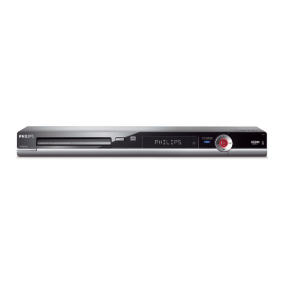
HDD + DVD Recorder
CLASS 1
LASER PRODUCT
Contents
1
2
3
4
5
6
7
© Copyright 2007 Philips Consumer Electronics B.V. Eindhoven, The Netherlands.
All rights reserved. No part of this publication may be reproduced, stored in a
retrieval system or transmitted, in any form or by any means, electronic,
mechanical, photocopying, or otherwise without the prior permission of Philips.
Published by KC-TE 0739 V&MA
Version 1.0
Contents
Page
2
4
7
10
13
15
15
16
17
18
20
21
22
23
24
24
25
8
26
9
27
28
Printed in the Netherlands
IC Description
Subject to modification
DVDR3465H/96
Page
29
30
31
32
32
33
33
34
35
36
37
38
39
40
41
42
43
43
56
56
57
EN 3139 785 33120
Advertisement
Table of Contents

Related Manuals for Philips DVDR3465H/96


Summary of Contents for Philips DVDR3465H/96
-
Page 1: Table Of Contents
Layout: Analog-Main Part (Top View) Spare Parts List © Copyright 2007 Philips Consumer Electronics B.V. Eindhoven, The Netherlands. All rights reserved. No part of this publication may be reproduced, stored in a retrieval system or transmitted, in any form or by any means, electronic, mechanical, photocopying, or otherwise without the prior permission of Philips. -
Page 2: Technical Specifications And Connection Facilities
: Fluke 54200 TV Signal S/N weighted : ≥ 45 dB (Quasi peak, generator CCIR 468) Test streams : Philips Standard test Harmonic distortion at 1 kHz : ≤ 1.5 % (FM: ± 25 kHz) pattern Channel Separation : ≥ 20 dB 1.3.1... - Page 3 3139 785 33120 Technical Specifications and Connection Facilities EN 3 Analogue Inputs / Outputs (OUT 3) COMPONENT VIDEO – Cinch (Y/Pb/Pr) According to EIO-770-1-A, EIA-770-2-A 1.4.1 Front Input Connectors (CAM 1) AUDIO – Cinch (L/R) 1.5. Digital Inputs/Outputs Input voltage : 2.2Vrms max Input impedance : >...
-
Page 4: Safety Information, General Notes & Lead Free Requirements
EN 4 3139 785 33120 Safety Information, General Notes & Lead Free Requirements 1.10. Playability NTSC YpbPr CVBS Video Playback 4.2 MHz:-3dB 4.2 MHz: -3dB Y: 4.2 MHz-3dB Playback Media: CD, CD-R/CD-RW, DVD, 5.8 MHz: -6dB 5.8 MHz: -6dB C: ≥ 700 kHz DVD+R/+RW, DVD-R/-RW, DVD-Video, Video CD/SVCD With Pscan:... -
Page 5: Safety Instructions
3139 785 33120 Safety Information, General Notes & Lead Free Requirements EN 5 Safety Information, General Notes & Lead Free Requirements Safety Instructions Warnings 2.1.1 General Safety 2.2.1 General Safety regulations require that during a repair: • All ICs and many other semiconductors are susceptible to •... - Page 6 Gemstar Development Corporation. The “Video Plus+” system is manufactured under licence from the Gemstar • Use only lead-free solder alloy Philips SAC305 with order Development Corporation. code 0622 149 00106. If lead-free solder-pate is required, please contact the manufacturer of your solder-equipment.
-
Page 7: Directions For Use
Directions For Use The following except of the Quick Use Guide serves as an introduction to the set. The Complete Direction for the Use can be downloaded in different languages from the internet site of Philips Customer care Center: www.p4c.philips.com... - Page 8 EN 8 3139 785 33120 Directions For Use...
- Page 9 Directions For Use 3139 785 33120 EN 9...
-
Page 10: Mechanical Instructions
EN 10 3139 785 33120 Mechanical Instructions Note : The position numbers given here refer to the Exploded view on chapter 9 Dismantling of the DVD Tray Cover manually Dismantling of the Basic Engine 1) Insert a screw-driver into the slot provided at the bottom 1) Remove 7 screws to loosen Top cover 240 . - Page 11 3139 785 33120 EN 11 Dismantling of Frontboard Dismantling of the Digital Board 1) Remove Screws as indicated to detach plate front loader 1) Remove 4 screws to loosen the Digital Board 1013 as 182 from Frame assembly 0920 as shown in Figure 4-5 shown in Figure 4-8.
- Page 12 EN 12 3139 785 33120 Dismantling of the Analogue Board 2) Service position for PSU Board is given in Figure 4-12. 1) Remove screws from the rear panel 230 to detach Analogue Board. 2) Service Position of Analogue Board is given in Figure 4-10. Insulation Sheet Insulation...
-
Page 13: Firmware Upgrading & Diagnostic Software
EN 13 Firmware Upgrading, Version Verification & HDD replacement 3139 785 33120 Firmware Upgrading & Version Verification and Preparations for HDD replacement Firmware Upgrading A. Preparation to upgrade firmware: 1. Unzip the zip-archive file 2. Start the CD Burning software and create a new CD project (data disc) with the following settings: File system: Joliet Format:... - Page 14 4. The TV connected to the set will display: BUILD :B5019V15 040 118E/Date: Aug 29 2007 Loader Version : 68.09.14.00 Macrovision Version : MPEG Chip ID: Audio DAC: Region Num:3 Developer:Philips PS3465H_96_R19.01 Stroke Version Software Version 5. Press <Setup> button to exit.
-
Page 15: Block Diagrams,Waveforms, Wiring Diagram
Block Diagrams, Waveforms, Wiring Diagram. 3139 785 33120 EN 15 Block Diagrams, Waveforms, Wiring Diagram Overall Bloc k Dia gr am of the Set ANALOG BO ARD F ront K e yboards 1201 CONTR OL AND COMMUNICATION LINES CONTR OL LINES 1300 DV -IN CVBSFIN... -
Page 16: Wiring Diagram
Block Diagrams, Waveforms, Wiring Diagram. 3139 785 33120 EN 16 Wiring Diagram... -
Page 17: Waveforms Of Analog Board
Block Diagrams, Waveforms, Wiring Diagram. 3139 785 33120 EN 17 Waveforms Waveforms of Analog Board I143 Y_OUT I142 C_OUT I144 CVBS_OUT I137 D_C I138 D_SY I139 D_Pr I140 D_CY I141 D_Pb I241 Audio-L out I242 Audio-R out I150 DIGITAL_OUT I311 XTAL IN I312 XTAL OUT... -
Page 18: Waveforms Of Digital Board
3139 785 33120 EN 18 Block Diagrams, Waveforms, Wiring Diagram. Waveforms of Digital Board AUD_BCKI T537 AUD_BCKO T541 AUD_DAI(0) T539 AUD_DAO(0) T543 AUD_MCKI T540 AUD_MCKO T544 AUD_WCKI T538 AUD_WCKO T542 VOA_BPb T518 VOA_GY T520 VOA_RPr T521 VOA_SY T522 VOA_SC T523 VOA_CVBS T524 T107 CLKI T108 CLKX... - Page 19 Block Diagrams, Waveforms, Wiring Diagram. 3139 785 33120 EN 19 Waveforms of Digital Board T351 XI T352 XO T461 1XTAL T462 2XTAL...
-
Page 20: Waveforms Of Front Board
3139 785 33120 EN 20 Block Diagrams, Waveforms, Wiring Diagram. Waveforms of Front Board F101 F112 F113 X2 F113 XT2 F133 XT1... -
Page 21: Test Point Overview For Analog Board
Block Diagrams, Waveforms, Wiring Diagram. 3139 785 33120 EN 21 Test Points Overview for Analog Board 3380_APAC_TPOINT.pdf 2006-05-03... -
Page 22: Test Point Overview For Digital Board
Block Diagrams, Waveforms, Wiring Diagram. 3139 785 33120 EN 22 Test Points Overview for Digital Board Digital Test Point 3139 243 34464_sh132_a3.eps 2007-09-26... -
Page 23: Test Point Overview For Front Board
3139 785 33120 EN 23 Block Diagrams, Waveforms, Wiring Diagram. Test Points Overview for Front Board Front Test Point 3139 243 33415_sh132_a3.eps 2007-09-26... -
Page 24: Circuit Diagram And Pwb Layout
Circuit Diagrams and PWB Layouts 3139 785 33120 EN 24 Circuit Diagrams and PWB Layouts Analog: Video Input/Output 1111-A D2 I126 H6 1111-B C2 I127 H6 1111-C E2 I128 H6 1112 F2 I129 H6 1113 G2 I130 H7 1114 F2 I131 H7 1121 I6 I132 H7... -
Page 25: Analog: Audio Adc/Dac
Circuit Diagrams and PWB Layouts 3139 785 33120 EN 25 Analog: Audio ADC/DAC 1201 D2 3253 I9 1202 C2 3254 I9 1203 F1 3260 I3 1205 E12 3261 H3 2201 D3 3262 I4 Audio ADC / DAC 2202 D3 3263 I5 2203 D3 3264 I5 2204 D3... -
Page 26: Analog: Tuner And Multi-Sound Processor (Msp)
Circuit Diagrams and PWB Layouts 3139 785 33120 EN 26 Analog: Tuner and Multi-Sound Processor (MSP) 1301 G12 1302 D1 1303 D1 2301 C3 2302 C3 2303 C4 2304 C4 2310 E2 Tuner and multi sound processor (MSP) 2311 E2 2312 E3 2313 E3 2314 F2... -
Page 27: Analog: Psu And Interfaces
Circuit Diagrams and PWB Layouts 3139 785 33120 EN 27 Analog: PSU and Interfaces 1401 D1 I408 C6 1402 C5 I409 D6 1403 A13 I410 D6 1404 C13 I413 D8 1405 D13 I415 B10 I421 A13 1406 E13 1407 F13 I422 B13 1408 F13 I423 B13... -
Page 28: Layout: Analog-Main Part (Top View)
Circuit Diagrams and PWB Layouts 3139 785 33120 EN 28 Layout: Analog-Main Part (Top View) 3380_APAC_TOPLAYR.pdf 2006-05-25... -
Page 29: Layout: Analog-Main Part (Bottom View)
Circuit Diagrams and PWB Layouts 3139 785 33120 EN 29 Layout: Analog-Main Part (Bottom View) Analog Bottom 3139 243 33342_sh132_a3.eps 2007-09-26... -
Page 30: Front: Front Panel - Display
Circuit Diagrams and PWB Layouts 3139 785 33120 EN 30 Front: Front Panel - Display 0100 D3 6105 D10 1100 E10 6106 D10 1101 F10 6107 D10 1201 G13 6108 D9 12VSTBY 1203 HUV-08SS65T 1203 A6 6109 E3 3104 1207 F2 6110 F3 VGNSTBY 1213 F1... -
Page 31: Front: Front Panel - Audio/Video-In
Circuit Diagrams and PWB Layouts 3139 785 33120 EN 31 Front: Front Panel - Audio/Video-In 1202 C1 1300 D3 1301-1 D1 1301-2 D1 1301-3 E1 1401 F1 1402 F3 1501 B2 1502 B3 2204 C1 2205 D3 2206 E2 2207 C2 2208 C1 2209 E2 I LINK 1394... -
Page 32: Layout: Front Panel (Top Copper Pattern) - Smd + Components
Circuit Diagrams and PWB Layouts 3139 785 33120 EN 32 Layout: Front Panel (Top Copper Pattern) - SMD + Components Front Top 3139 243 33415_sh132_a3.eps 2007-09-27 Layout: Front Panel (Bottom Copper Pattern) - Components Front Bottom 3139 243 33415_sh132_a3.eps 2007-10-08... -
Page 33: Front: Standby
Circuit Diagrams and PWB Layouts 3139 785 33120 EN 33 Front: Standby Layout: Standby (Top View) 1302 C1 1303 C3 2301 C1 6300 C2 6301 C2 F300 C2 F301 C2 I300 C3 1303 1302 I300 F300 EVQ11L05R Front Standby Top 3139 243 33395_sh132_a4.eps 2007-09-27 WH02D-1 F301 Layout: Standby (Bottom View) -
Page 34: Digital: Back-End Processor
Circuit Diagrams and PWB Layouts 3139 785 33120 EN 34 Digital: Back-End Processor 1101 B6 3166 B8 T117 H5 1105 E5 3167 B8 T118 H6 1111 D6 3168 F9 T119 I5 2101 B6 3169 F9 Back-end Processor 2102 B6 3171-1 G10 3V3BE Communication (COM) 2105 E8... -
Page 35: Digital: Memory
Circuit Diagrams and PWB Layouts 3139 785 33120 EN 35 Digital: Memory 2201 D1 3259-3 C11 2202 D1 3259-4 C11 2203 D3 3261-1 C11 Memory 2204 D3 3261-2 C11 2205 D2 3261-3 C11 2211 A4 3261-4 C11 2212 B4 3263-1 C11 2213 B4 3263-2 C11 2214 B4... -
Page 36: Digital: Ieee 1394 Physical Layer
Circuit Diagrams and PWB Layouts 3139 785 33120 EN 36 Digital: IEEE 1394 Physical Layer 1351 D5 2301 D6 2302 D6 2303 D6 2304 D6 IEEE1394 Physical Layer 2305 D7 2306 D7 2307 D7 2321 G5 2341 G9 2343 G9 2351 D5 2352 E5 2361 E5... -
Page 37: Digital: Video Input Processor
Circuit Diagrams and PWB Layouts 3139 785 33120 EN 37 Digital: Video Input Processor 1461 D7 T416 C9 2401 C9 T421 E6 2402 C9 T422 E6 2403 C9 T423 F7 2404 C9 T431 G10 Video Input Processor 2411 B9 T432 F10 2412 B9 T433 E7 2413 B9... -
Page 38: Digital: Interfaces
Circuit Diagrams and PWB Layouts 3139 785 33120 EN 38 Digital: Interfaces T516 C8 1501 C1 3572 F2 T672 F3 1502 H13 3573-1 G2 T517 A5 T673 F3 1511 A7 3573-2 G2 T518 A9 T674 G3 1512 A7 3573-3 G2 T519 A9 T675 G3 1521 A10... -
Page 39: Layout: Digital-Main Part (Top View)
Circuit Diagrams and PWB Layouts 3139 785 33120 EN 39 Layout: Digital-Main Part (Top View) Digital Top 3139 243 34464_sh132_a3.eps 2007-09-27... -
Page 40: Layout: Digital-Main Part (Bottom View)
Circuit Diagrams and PWB Layouts 3139 785 33120 EN 40 Layout: Digital-Main Part (Bottom View) Digital Bottom 3139 243 34464_sh132_a3.eps 2007-09-27... -
Page 41: Power Supply Unit: Schematic
Circuit Diagrams and PWB Layouts 3139 785 33120 EN 41 Power Supply Unit: Schematic AC7012_Sch_Rev,4.eps 2007-09-27... -
Page 42: Power Supply Unit: Layout
Circuit Diagrams and PWB Layouts 3139 785 33120 EN 42 Power Supply Unit: Layout The PSU Layout is not available... -
Page 43: Ic Description
IC description 3139 785 33120 EN 43 IC Description Analog Board IC7304 - Multistand Sound Processor Family BLOCK DIAGRAM 23 24 28 32 MSP34x5G ANA_IN+ DACM_L Loud- Pre- speaker processing Modulator sound ANA_IN- DACM_R proeessing I2S_DA_IN1 Loud- Pre- speaker I2S_DA_OUT processing sound I2S_DA_IN2... - Page 44 EN 44 3139 785 33120 IC Description PIN CONFIGURATION VREF1 DACM_L SC1_OUT_R DACM_R SC1_OUT_L VREF2 AHVSUP 33 32 31 30 29 28 27 26 25 24 23 CAPL_M RESETQ AHVSS I2S_DA_IN2 AGNDC DVSS SC2_IN_L DVSUP SC2_IN_R ADR_CL MSP 34x5G I2S_DA_IN1 SC1_IN_L I2S_DA_OUT SC1_IN_R...
- Page 45 IC description 3139 785 33120 EN 45 PIN DESCRIPTION AND CONFIGURATION SDIN SCLK AMUTEC LRCK AOUTA MCLK VA_H AOUTB DIF1(SCL/CCLK) BMUTEC DIF0(SDA/CDIN) DEM(AD0/CS) VBIAS Pin Name Pin Description SDIN Serial Audio Data Input ( Input ) - Input for two’s complement serial audio data. SCLK Serial Clock ( Input ) - Serial clock for the serial audio interface.
- Page 46 EN 46 3139 785 33120 IC Description IC7203 - 96KHz Sampling 24-bit stereo audio ADC BLOCK DIAGRAM V DDA V SSA V RP V RN V ref SYSCLK d th V DDD UDA1361TS V SSD V INL MSSEL DECIMATION CLOCK FILTER CONTROL PWON...
- Page 47 IC description 3139 785 33120 EN 47 Digital Board IC7301 - IEEE 1394a-2000 one port cable Transceiver/Arbiter BLOCK DIAGRAM Received Data Decoder/Retimer Link Interface S SCL TPA+ CTL0 TPA– CTL1 Cable Port TPB+ Arbitration and Control TPB– State Machine Logic C/L O Bias Voltage Current...
- Page 48 EN 48 3139 785 33120 IC Description PIN CONFIGURATION PHP package terminal diagram PHP PACKAGE (TOP VIEW) 47 46 45 44 43 40 39 38 AGND SYSCLK CTL0 CTL1 AGND TPBIAS TSB41AB1 TPA+ TPA– TPB+ TPB– AGND 14 15 17 18 19 20 21 22 23 24 Figure 8-13...
- Page 49 IC description 3139 785 33120 EN 49 PIN DESCRIPTION TERMINAL TYPE TYPE DESCRIPTION DESCRIPTION NAME PHP NO. AGND 26, 32, 36 Supply – Analog circuit ground terminals. These terminals should be tied together to the low-impedance circuit board ground plane. AV DD 25, 35 Supply...
- Page 50 EN 50 3139 785 33120 IC Description TERMINAL TYPE TYPE DESCRIPTION DESCRIPTION NAME PHP NO. DGND 14, 46, 47 Supply – Digital circuit ground terminals. These terminals should be tied together to the low-impedance circuit board ground plane. DV DD 21, 44, 45 Supply –...
- Page 51 IC description 3139 785 33120 EN 51 TERMINAL TYPE TYPE DESCRIPTION DESCRIPTION NAME PHP NO. PLLGND Supply – PLL circuit ground terminals. These terminals should be tied together to the low-impedance circuit board ground plane. PLLV DD Supply – PLL circuit power terminals. A combination of high-frequency decoupling capacitors near each terminal is suggested, such as paralleled 0.1 µF and 0.001 µF.
- Page 52 EN 52 3139 785 33120 IC Description IC7401 - 4x10bit DigitalVideo Decoder with microvision BLOCK DIAGRAM Copy CVBS/Y/G Protection Data Detector Slicer Analog Front End VI_1_A Composite and S-Video Processor CVBS/ VI_1_B ADC1 Pb/B/C VI_1_C Luma CVBS/Y Separation Processing YCbCr 5-line VI_2_A Y[9:0]...
- Page 53 IC description 3139 785 33120 EN 53 PIN DESCRIPTION TERMINAL DESCRIPTION DESCRIPTION NAME NUMBER Analog Video VI_1_A VI_1_x: Analog video input for CVBS/Pb/B/C VI_1_B VI_2_x: Analog video input for CVBS/Y/G VI_1_C VI_3_x: Analog video input for CVBS/Pr/R/C VI_2_A VI_4_A: Analog video input for CVBS/Y VI_2_B Up to 10 composite, 4 S-video, and 2 composite or 3 component video inputs (or a combination thereof) VI_2_C...
- Page 54 EN 54 3139 785 33120 IC Description TERMINAL DESCRIPTION DESCRIPTION NAME NUMBER Host Interface I 2 C clock input I 2 C data bus Power Supplies AGND Analog ground. Connect to analog ground. A18GND_REF Analog 1.8-V return A18VDD_REF Analog power for reference 1.8 V CH1_A18GND CH2_A18GND Analog 1.8-V return...
-
Page 55: Top View
IC description 3139 785 33120 EN 55 IC7595 - Voltage Detector Series with Programmable Delay BLOCK DIAGRAM NCP303LSNxxT1 Open Drain Output Configuration Input Reset Output Figure 8-18 PIN DESCRIPTION AND CONFIGURATION PIN CONNECTIONS AND MARKING DIAGRAM Reset Output Input N.C. Ground xxx = 302 or 303 = Year... -
Page 56: Exploded View & Spare Parts List
EN 56 3139 785 33120 Exploded View & Spare Parts List Exploded View Figure 9-1... -
Page 57: Spare Parts List
Exploded View & Spare Parts List 3139 785 33120 EN 57 DVDR3465H/96 0110 313924414511 COVER TRAY DVDR3465H 0131 313924125081 CLIP ESD DVDR3380 0179 313924125041 SPRING EMC 0180 313924124361 SPRING AV DVDR3400 0184 313911426671 BUSH, AC CORD 0186 313911435693 SPACER 5MM 0189 282203100051 FAN 12VDC 0.6W 3000RPM...
Need help?
Do you have a question about the DVDR3465H/96 and is the answer not in the manual?
Questions and answers