Sony XM-440EX Service Manual
Hide thumbs
Also See for XM-440EX:
- Operating instructions (4 pages) ,
- Operating instructions (4 pages)

Related Manuals for Sony XM-440EX


Summary of Contents for Sony XM-440EX
-
Page 1: Specifications
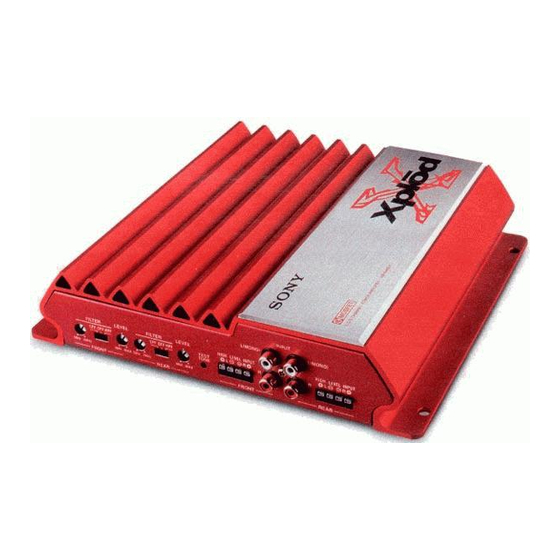
XM-440EX/440NX SERVICE MANUAL Canadian Model AEP Model E Model XM-440EX UK Model XM-440NX Photo : XM-440EX SPECIFICATIONS STEREO POWER AMPLIFIER MICROFILM... -
Page 2: Table Of Contents
TABLE OF CONTENTS Specifications ................1 1. GENERAL ............... 3 2. DISASSEMBLY 2-1. Main Board Removal ........... 6 3. DIAGRAMS 3-1. Block Diagram .............. 7 3-2. Printed Wiring Boards ..........9 3-3. Schematic Diagrams –MAIN (1/2) Section – ..... 10 3-4. -
Page 3: General
SECTION 1 This section is extracted from instruction manual. GENERAL... -
Page 6: Disassembly
SECTION 2 DISASSEMBLY Note : Follow the disassembly procedure in the numerical order given. 2-1. MAIN BOARD REMOVAL 1 Two screws (+BTP3x4) 2 Two screws (+BTP3x4) 9 Screw 8 Two screws (+BTP3x4) (+BTP3x8) 7 Two screws (+BTP3x8) 3 Bottom plate 6 Two screws 4 Screw (+BTP3x6) -
Page 7: Diagrams
XM-440EX/440NX SECTION 3 DIAGRAMS 3-1. BLOCK DIAGRAM SW101 (2/2) FILTER CN904 REAR SPEAKER FILTER H.P.F RV101 (2/4) L.P.F RV101 (4/4) L.P.F FILTER FILTER DIFFERENTIAL DRIVE AMP DRIVE AMP DRIVE AMP INPUT Q204 Q204 Q204 (MONO) Q263 CNJ301 IC203 (1/2) IC101 (2/2) - Page 8 XM-440EX/440NX • WAVEFORMS THIS NOTE IS COMMON FOR PRINTED WIRING BOARDS AND SCHEMATIC DIAGRAMS. (In addition to this, the necessary 28Vp-p 12.8Vp-p note is printed in each block.) 31 µ sec 31 µ sec For schematic diagrams. Note: • All capacitors are in µF unless otherwise noted.
-
Page 9: Printed Wiring Boards
XM-440EX/440NX 3-2. PRINTED WIRING BOARDS • Semiconductor Location Ref. No. Location Ref. No. Location D101 Q203 D102 Q204 D201 Q205 D202 Q206 D301 Q207 D302 Q208 D401 Q209 D402 Q210 D501 Q211 D901 Q212 MAIN BOARD D902 Q301 D903 Q302... -
Page 10: Schematic Diagrams -Main (1/2) Section
XM-440EX/440NX 3-3. SCHEMATIC DIAGRAMS – MAIN (1/2) SECTION – • See page 8 for Waveforms. • See page 9 for Printed Wiring Boards. -
Page 11: Schematic Diagrams -Main (2/2) Section
XM-440EX/440NX 3-4. SCHEMATIC DIAGRAMS – MAIN (2/2) SECTION – • See page 8 for IC Block Diagrams. • See page 9 for Printed Wiring Boards. -
Page 12: Exploded View
SECTION 4 SECTION 5 MAIN EXPLODED VIEW ELECTRICAL PARTS LIST NOTE: Note: • The mechanical parts with no reference number in • -XX, -X mean standardized parts, so they may have • Due to standardization, replacements in the parts list •... - Page 13 MAIN Ref. No. Part No. Description Remark Ref. No. Part No. Description Remark C309 1-126-963-11 ELECT 4.7uF C919 1-126-968-11 ELECT 100uF C310 1-126-963-11 ELECT 4.7uF C920 1-126-968-11 ELECT 100uF C311 1-104-664-11 ELECT 47uF C921 1-126-955-11 ELECT 4700uF C922 1-126-955-11 ELECT 4700uF C312 1-163-239-11 CERAMIC CHIP...
- Page 14 MAIN Ref. No. Part No. Description Remark Ref. No. Part No. Description Remark <FUSE> < PILOT LAMP > F901 1-532-947-11 FUSE (BLADE TYPE)(AUTO FUSE)(30A) PL901 1-518-540-11 LAMP, PILOT < IC > < TRANSISTOR > IC101 8-759-394-81 IC NJM4559M-TE2 Q101 8-729-052-02 TRANSISTOR KTD1304 IC102 8-759-394-81 IC NJM4559M-TE2 Q102...
- Page 15 MAIN Ref. No. Part No. Description Remark Ref. No. Part No. Description Remark Q907 8-729-034-51 TRANSISTOR KTC3875 R147 1-249-883-11 CARBON 1/4W R151 1-216-081-00 METAL CHIP 1/10W Q908 8-729-034-51 TRANSISTOR KTC3875 R152 1-216-035-00 METAL CHIP 1/10W Q916 8-729-034-51 TRANSISTOR KTC3875 Q917 8-729-052-00 TRANSISTOR SKP65N06 R153 1-216-073-00 METAL CHIP...
- Page 16 MAIN Ref. No. Part No. Description Remark Ref. No. Part No. Description Remark R307 1-216-073-00 METAL CHIP 1/10W R419 1-216-057-00 METAL CHIP 2.2K 1/10W R420 1-216-057-00 METAL CHIP 2.2K 1/10W R308 1-216-069-00 METAL CHIP 6.8K 1/10W R421 1-216-057-00 METAL CHIP 2.2K 1/10W R309...
- Page 17 MAIN Ref. No. Part No. Description Remark Ref. No. Part No. Description Remark R918 1-216-089-00 RES-CHIP 1/10W < THERMISTOR > R919 1-216-073-00 METAL CHIP 1/10W R920 1-216-061-00 METAL CHIP 3.3K 1/10W TH901 1-810-506-21 THERMISTOR NTH5G39B223K01TE R921 1-216-073-00 METAL CHIP 1/10W TH902 1-809-664-51 THERMISTOR, POSITIVE R922...
- Page 18 XM-440EX/440NX Sony Corporation 9-870-068-11 2000A090267-1 Mobile Electronics Division Company Printed in Japan © 2000. 1 Published by General Engineering Dept.
Need help?
Do you have a question about the XM-440EX and is the answer not in the manual?
Questions and answers