
Related Manuals for Yardworks 060-1784-4


Summary of Contents for Yardworks 060-1784-4
- Page 1 CORDLESS SELF-PROPELLED LAWN MOWER 060-1784-4 Owner's Manual TOLL FREE HELPLINE: 1- 866-523-5218 IMPORTANT: Read all safety rules and instructions carefully before using this product.
-
Page 2: Table Of Contents
Slope Gauge and Operation 16-17 Maintenance Storage Service Troubleshooting Warranty Exploded View/Parts List 23-27 SPECIFICATIONS Model Number 060-1784-4 Motor 24 V Battery 24 V, 20 Ah lead-acid Charge time approx. 15 hours No-load Speed 3,300 RPM Cutting Path 18” (45.7 cm) Height Adjustments 7 positions, 1 1/4 −... -
Page 3: Safe Operation
SAFE OPERATION GENERAL SAFETY RULES READ ALL INSTRUCTIONS CAREFULLY WARNING: This symbol indicates important safety instructions. If these instructions are not followed, it could endanger the personal safety and/or property of the operator and others. Read and understand all instructions in this manual before attempting to operate the mower. - Page 4 SAFE OPERATION 3. In order to avoid contact with the blade or injury caused by a thrown object, stay in the operating zone behind the handles, and keep children and bystanders at least 100' (30 m) away from the mower while it is in operation. Stop the motor immediately if someone enters the mowing area.
- Page 5 BATTERY & CHARGER CAUTION: USE ONLY YARDWORKS APPROVED REPLACEMENT BATTERIES. OTHER BATTERIES MAY CAUSE INJURY OR DAMAGE TO THE MOWER. Use with YARDWORKS 24V 20 Ah battery 60-2142-6. The battery that is supplied with this mower is a maintenance-free, sealed, 24 V storage battery. It can be tipped without danger of acid spillage.
-
Page 6: Safe Operation
SAFE OPERATION CHARGER SAFETY RULES Charge the mower battery in a dry area that is protected from the weather. Do not expose the mower or the charger to rain. Do not charge the battery in a wet location. Operate the battery charger in temperatures between 23°... -
Page 7: Assembling The Lawn Mower
ASSEMBLING YOUR LAWN MOWER LOOSE PARTS IN CARTON • Battery • Charger • Grass catcher bag • Mulching plug • Owner’s manual Note: • Carefully remove the parts from the box. • Inspect the parts carefully in order to verify that no breakage or damage occurred during shipping. •... - Page 8 ASSEMBLING YOUR LAWN MOWER CHARGING PROCEDURE RECYCLE RECYCLER Note: The battery can be charged in or out of the mower. The charger that is supplied with this mower is a specially designed 2-stage charger. Step 1: The red light will light up during the recharge cycle. Step 2: The green light will light up when the battery is fully charged.
- Page 9 ASSEMBLING YOUR LAWN MOWER INSTALLING THE GRASS CATCHER BAG (Fig. 2) 1. Lift the chute cover (1). 2. Lift the grass catcher by its handle (2) and place under the chute cover so that the hooks (3) on the grass catcher frame are seated into the slots in the handle bracket. 3.
- Page 10 ASSEMBLING YOUR LAWN MOWER INSTALLING AND REMOVING THE MULCHING PLUG (Fig. 3) 1. To remove the mulching plug, lift the chute cover (1). 2. Grasp the handle (2) of the mulching plug and pull the mulching plug out using the handle. 3.
-
Page 11: Description Of Parts
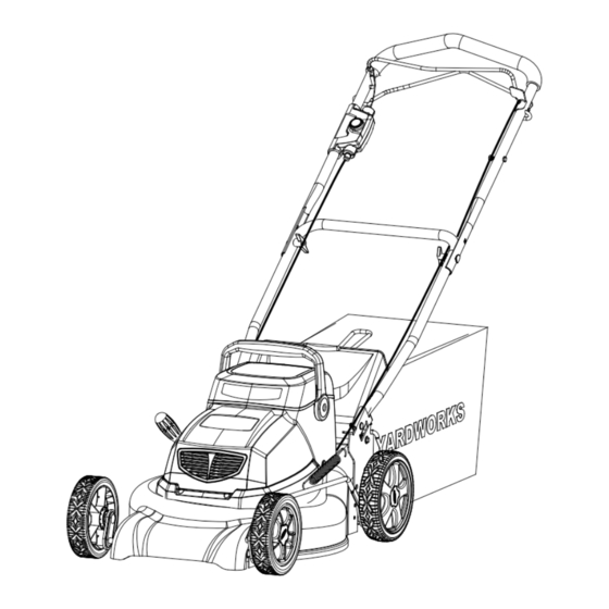
DESCRIPTION OF PARTS DIAGRAM OF THE MOWER Read this owner's manual and safety rules carefully before operating the mower. Compare the illustration below to the mower in order to become familiar yourself with the location of the various controls and adjustments. Save this manual for future reference. Upper bail Lower bail Start button... -
Page 12: Operating The Lawn Mower
OPERATING THE LAWN MOWER STARTING/STOPPING THE MOWER (Fig. 4) To start the motor: 1. Press and hold the start button (1). 2. Pull the upper bail (2) toward the handle to start the mower. 3. Release the button (1). To stop the motor: Release the upper bail (2). - Page 13 OPERATING THE LAWN MOWER CUTTING HEIGHT ADJUSTMENT (Fig. 5) A single height adjustment lever is used to adjust the cutting height. The lever is located beside the right rear wheel and has 7 height positions, ranging from 1 1/4 to 3 1/2" (3.2 to 8.9 cm). Before making any adjustments, release the switch to turn the mower off;...
- Page 14 OPERATING THE LAWN MOWER BATTERY CAPACITY INDICATORS When you start the mower, the lights will indicate the battery’s capacity, according to the following chart. Yellow Green Green Green BCI switch Lights Capacity At Full capacity 3 Green Lights 2 Green Lights At 60% capacity At 45% capacity 1 Green Light...
- Page 15 OPERATING THE LAWN MOWER BATTERY USE & CARE • The battery that is supplied with this mower is a maintenance-free, sealed, 24 V storage battery. It can be tipped without danger of acid spillage. • For optimal performance, charge the battery every two weeks, even when it is not in use. •...
-
Page 16: Slope Gauge And Operation
SLOPE GAUGE & OPERATION WARNING: Slopes are a major factor related to accidents involving slips and falls, which can result in severe injury. Operating the mower on a slope requires extra caution. If you feel uneasy on a slope, do not mow it. For your safety, use the slope gauge that is included as part of this manual to measure slopes before operating this unit on a sloped or hilly area. -
Page 17: Slope Gauge And Operation
SLOPE GAUGE & OPERATION MOWING TIPS NOTE: A sharp blade will greatly enhance the performance of the mower, especially when cutting high grass. Be sure to check the blade and to sharpen it at least once per year, as described in the Maintenance section. -
Page 18: Maintenance
MAINTENANCE REPLACEMENT THE BLADE WARNING: Always protect your hands by wearing heavy gloves and/or wrapping the cutting edges with rags or other materials when performing any maintenance on the blades. ALWAYS remove battery when servicing or transporting the mower. 1. REMOVE BATTERY. 2. -
Page 19: Storage
STORAGE The following steps should be taken in order to prepare the lawn mower for storage. 1. Clean the mower as described in the previous section. 2. Inspect the blade, and replace it or sharpen it, if required (refer to the Maintenance section). 3. -
Page 20: Service
SERVICE 1. When servicing the mower, use only replacement parts that are available from the manufac- turer. In order to obtain replacement parts, call the toll-free helpline, at 1-866-523-5218. The use of parts that do not meet the original equipment specifications may lead to improper performance, and may compromise safety. -
Page 21: Troubleshooting
TROUBLESHOOTING Proble m Possible Cause(s) Corrective Action 1. The battery is not charged. 1. Charge the battery 2. Replace the switch (call the toll- 2. The switch is defective. free helpline, at 1-866-523-5218 The mower does not start. 3. The battery is not attached to the 3. -
Page 22: Warranty
WARRANTY For TWO YEARS from the date of purchase within Canada, YARDWORKS ® CANADA will, at its option, repair or replace for the original purchaser, free or charge, any part or parts that are found to be defective in material or workmanship. -
Page 23: Exploded View/Parts List
EXPLODED VIEW... - Page 24 EXPLODED VIEW...
-
Page 25: Parts List
PARTS LIST Part No. Model No. Description Cable assy. 31103463-1 33304250-1 Upper bail 34115250 Sponge 33305250-1 Lower bail 3220439 Nut M5 Bail stop 33323250 32208234 Bolt M5*30 33303250-2 Upper handle 32204234 Bolt M6*35 3220537 Nut M6 Drive cable 31903250 32204283 Bolt 34108283 Knob... - Page 26 PARTS LIST Part No. Model No. Description Cotton pin 3290134 33901234-1 Front wheel axle 33903234-1 Rear wheel axle 33908234 Housing 32101234 Bearing Clip 32902234 Clip 32905234 32908234 Flat washer 33204234 Small gear wheel 32906234 33302234-2 Link bar Retarder 31102234 33318234 Spring 32902250 33322250...
- Page 27 PARTS LIST Part No. Model No. Description Battery assy. 31103237-2 3220345 Screw 74-1 74-2 34104229 Battery Housing 32201229 Screw 74-3 36501229 Rubber cover for connector 74-4 74-5 3660239-1 2 X 12 V 20Ah SLA BATTERY 36502229 Connector terminal 74-6 3050245 Wire (blue) 74-7 3050145...
Need help?
Do you have a question about the 060-1784-4 and is the answer not in the manual?
Questions and answers