
Related Manuals for Yardworks 060-1773-0


Summary of Contents for Yardworks 060-1773-0
- Page 1 20" (50.8 cm) Electric Lawn Mower 060-1773-0 Owner's Manual TOLL-FREE HELPLINE: 1 8 66 523-5218 IMPORTANT: Read all safety rules and instructions carefully before using this product.
-
Page 2: Table Of Contents
3-in-1: Mulch, side discharge or rear bag. Weight: 50 lbs (22.7 kg) Use with YARDWORKS replacement blade 60-7119-4 READ ALL INSTRUCTIONS! WARNING: This symbol indicates important safety instructions. if these instuctions are not followed, it could endanger the personal safety and/or property of the operator and others. -
Page 3: Safe Operation
SAFE OPERATION GENERAL OPERATION 1. Carefully read all instructions on the mower and in the manual before attempting to assemble and operate the mower. Keep this manual in a safe place for future reference, and consult it regularly. 2. Become familiar with all controls and their proper operation. Know how to stop the mower and how to disengage the power in an emergency. -
Page 4: Operating On A Slope
17. Do not abuse the cord by pulling the mower by the cord or yanking on the cord in order to disconnect it from the outlet. Keep the cord away from heat, oil, and sharp edges. 18. Many injuries occur as a result of the mower being pulled over the operator's foot during a fall caused by slipping or tripping. -
Page 5: Save These Instructions
SE RVICE 1. When servicing the mower, use only replacement parts that are listed in this manual. The use of parts that do not meet the original equipment specifications may lead to improper performance, and may compromise safety. 2. Before cleaning, repairing, or inspecting, verify that the blade and all moving parts have come to a complete stop. -
Page 6: Assembly Instructions
ASSEMBLY INSTRUCTIONS Parts List Mulch plug Grass catcher bag Side discharge chute NOTE: Carefully remove the parts from the box. • Inspect the parts carefully to make sure no breakage or damage occurred during shipping. • Do not discard the packing material until all parts are examined. •... - Page 7 INSTALLING THE GRASS CATCHER BAG (Fig. 2) 1. Lift the chute cover (1). 2. While holding the chute cover (1) up, place the hanger hooks (2) of the grass catcher bag into the opening on the chute cover (1) in order to allow the hanger hooks to attach to the rod (3) that secures the chute cover. Fig.
- Page 8 INSTALLING THE SIDE DISCHARGE CHUTE (Fig. 3) 1. Pull open the side discharge cover (1) . 2. Align the discharge chute arrows with the positioning arrows on the mower deck, and then slide the discharge chute (2) in, as shown. t i s release the chute and the cover.
- Page 9 INSTALLING AND REMOVING THE MULCHING PLUG (Fig. 4) 1. To remove the mulching plug, lift the chute cover (1) and pull the mulching plug out using the handle. . t i Fig. 4...
-
Page 10: Know Your Lawn Mower
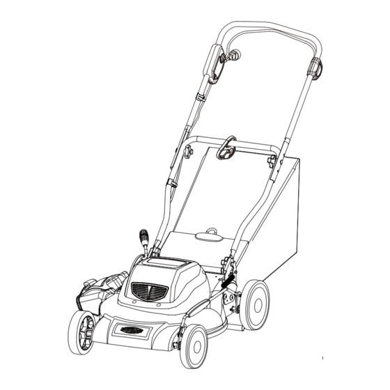
KNOW YOUR LAWN MOWER Bail switch Power button Circuit breaker per handle Lower handle Height adjustment lever Grass catcher bag Side discharge cover Side discharge Motor housing chute Wheels Read this operator´s manual and safety rules before operating your lawn mower. Compare the illustration to your lawn mower in order to familiarize yourself with the location of various controls and adjustments. -
Page 11: Operating Your Lawn Mower
OPERATING YOUR LAWN MOWER STARTING AND STOPPING THE MOWER (Fig. 5) Starting the mower: • Plug the mower into an approved outdoor extension cord. • Press and hold the Power button (1). This makes the Bail switch operational. • Pull the bail switch (2) upward to the handlebar to operate and release the Power button. Stopping the mower: •... - Page 12 ADJUST THE CUTTING HEIGHT (Fig. 6) 1. Adjust the cutting height as desired. 2. Simply depress the lever(1) towards the wheel then move to desired position. This sets all wheels to the same position. 3. To raise the height, pull the height adjustment lever from the current stop position towards the back of the mower.
- Page 13 ADJUST THE UPPER HANDLE HEIGHT (Fig. 7) You may raise or lower the upper handle to a position comfortable for you. 1. Loosen the upper handle knob. 2. move the upper handle to the desired position. There are 3 positions for you to choose. 3.
-
Page 14: Slope Gauge &Operation
SLOPE GAUGE &OPERATION WARNING: Slopes are a major factor related to accidents involving slips and falls, which can result in severe injury. Operating the mower on a slope requires extra caution. If you feel uneasy on a slope, do not mow it. For your safety, use the slope gauge that is included as part of this manual to measure slopes before operating this unit on a sloped or hilly area. -
Page 15: Mulching Tips
MULCHING TIPS NOTE: INSPECT THE AREA WHERE THE MOWER IS TO BE USED, AND REMOVE ALL STONES, STICKS, WIRE, BONES, AND OTHER DEBRIS THAT MIGHT BE THROWN BY THE ROTATING BLADE. 1. Release the switch to turn the mower OFF when crossing any graveled area (stones can be thrown by the blade). -
Page 16: Maintenance
WARNING: Always protect your hands by wearing heavy gloves and/or wrapping the cutting edges with rags or other materials when performing any maintenance on the blades. Use only a YARDWORKS replacement blade (60-7119-4). 1. RELEASE THE SWITCH LEVER TO TURN THE MOWER OFF, WAIT FOR THE BLADE TO COME TO A COMPLETE STOP. - Page 17 C LEAN THE MOWER WARNING: To reduce the risk of electric shock, do not expose the mower to water. The underside of mower deck should be cleaned after each use as grass clippings, leaves, dirt and other debris will accumulate causing rust and corrosion. Remove any buildup of grass and leaves on or around the motor cover (do not use water).
-
Page 18: Storage
STORAGE The following steps should be taken to prepare the lawn mower for storage. Make certain the power cord is disconnected. Clean mower as instructed in previous section. Inspect and replace/sharpen blade, if required. Refer to the Maintenance section. Store mower in a dry, clean area. Do not store next to corrosive materials, such as fertilizer and rock salt. -
Page 19: Troubleshooting
TROUBLESHOOTING Problem Possible Cause(s) Solution The handle is not in Carriage bolts. Adjust the height of the handle, position. and verify that the carriage bolts are properly seated. Tighten the knobs. The mower does not start. The power cord is disconnected Reconnect the cord, and use the from the switch. -
Page 20: Warranty
WARRANTY For TWO YEARS from the date of purchase within Canada, YARDWORKS ® CANADA will, at its option, repair or replace for the original purchaser, free or charge, any part or parts that are found to be defective in material or workmanship. - Page 21 EXPLODED VIEW...
- Page 22 EXPLODED VIEW...
-
Page 23: Parts List
PARTS LIST Model Num. Description Model Num. Description 31109228 Motor cover Assy. 3221037 Lock nut 3220435 3340137-2 Extension spring Machine screw Motor Assy. Link bar 3610138-1 33303227-1 3110638-3 Carbon brush Assy. Screw 32202227 3220537 34112227 Link bar bracket (right) Lock Nut Bolt 34111227 Link bar bracket (left)
Need help?
Do you have a question about the 060-1773-0 and is the answer not in the manual?
Questions and answers