Table of Contents
Advertisement
Quick Links
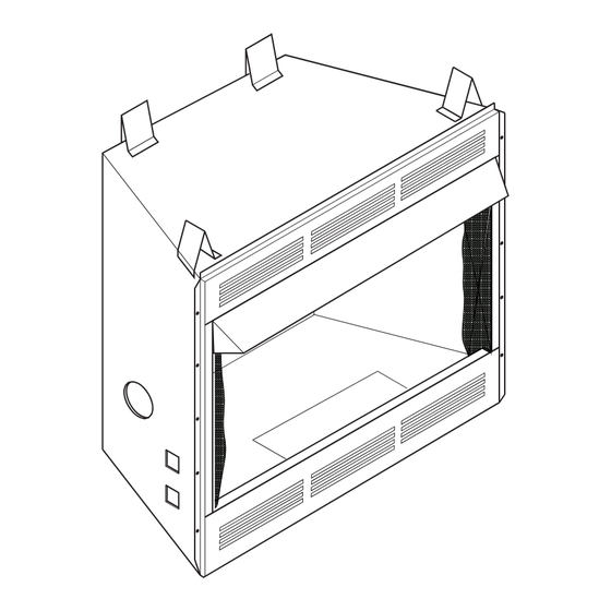
UNVENTED (VENT-FREE) UNIVERSAL FIREBOX
OWNER'S OPERATION AND INSTALLATION MANUAL
PFS
®
US
CIRCULATING MODELS
(V)BFBF36, (V)BFBL36, (V)BFBF42, AND (V)BFBL42 SERIES
WARNING: If the information in this manual is not
followed exactly, a fire or explosion may result causing
property damage, personal injury or loss of life.
FOR USE ONLY WITH A LISTED GAS-FIRED UNVENTED
DECORATIVE ROOM HEATER NOT TO EXCEED 40,000
BTU/HR. DO NOT BUILD A WOOD FIRE.
Carefully review the instructions supplied with the
decorative type unvented room heater for the minimum
fireplace size requirement.
DO NOT INSTALL AN APPLIANCE IN THIS FIREBOX
UNLESS THIS FIREBOX MEETS THE MINIMUM DIMEN-
SIONS REQUIRED FOR THE INSTALLATION.
This firebox has been tested and approved under ANSI
Z21.91 for use with any ANSI Z21.11.2 approved gas logs.
INSTALLER: Leave this manual with the appliance.
CONSUMER: Retain this manual for future reference.
For more information, visit www.fmiproducts.com
Advertisement
Table of Contents

Related Manuals for FMI (V)BFBF36 series


Summary of Contents for FMI (V)BFBF36 series
- Page 1 UNVENTED (VENT-FREE) UNIVERSAL FIREBOX OWNER’S OPERATION AND INSTALLATION MANUAL ® CIRCULATING MODELS (V)BFBF36, (V)BFBL36, (V)BFBF42, AND (V)BFBL42 SERIES WARNING: If the information in this manual is not followed exactly, a fire or explosion may result causing property damage, personal injury or loss of life. FOR USE ONLY WITH A LISTED GAS-FIRED UNVENTED DECORATIVE ROOM HEATER NOT TO EXCEED 40,000 BTU/HR.
-
Page 2: Table Of Contents
TABLE OF CONTENTS Safety ..............2 Installation ............8 Local Codes............3 Replacement Parts ..........17 Product Features ..........3 Technical Service..........17 Locating Firebox ..........4 Accessories ............17 Product Specifications ......... 4 Parts ..............18 Air For Combustion and Ventilation ..... 6 Warranty ..........Back Cover SAFETY WARNING: Improper instal-... -
Page 3: Local Codes
SAFETY Continued You must operate this fireplace 3. Use only the provided hood or appropri- with the provided fireplace ate hood accessory. See Accessories on page 17. screen, hood if provided, in 4. Vent-free gas log heaters installed in these place. -
Page 4: Locating Firebox
LOCATING FIREBOX PLANNING 2. Everything needed to complete installation. 3. These models CANNOT be installed in a Plan where you will install the firebox. This will bedroom unless the maximum Btu rating save time and money later when you install of the installed vent-free log set is less the firebox. - Page 5 PRODUCT SPECIFICATIONS Continued 42" MODELS Figure 2 - Firebox Dimensions 42'' Models www.fmiproducts.com 126333-01A...
-
Page 6: Air For Combustion And Ventilation
AIR FOR COMBUSTION AND VENTILATION Unusually Tight Construction WARNING: This heater shall The air that leaks around doors and windows not be installed in a room or space may provide enough fresh air for combustion unless the required volume of in- and ventilation. -
Page 7: Local Codes
AIR FOR COMBUSTION AND VENTILATION Continued DETERMINING FRESH-AIR FLOW 4. Compare the maximum Btu/Hr the space can support with the actual amount of FOR HEATER LOCATION Btu/Hr used. Determining if You Have a Confined or _________ Btu/Hr (maximum the space Unconfined Space can support) Use this work sheet to determine if you have... -
Page 8: Installation
AIR FOR COMBUSTION AND VENTILATION Continued VENTILATION AIR Ventilation Air From Outdoors Provide extra fresh air by using ventilation Ventilation Air From Inside Building grills or ducts. You must provide two perma- This fresh air would come from an adjoining nent openings: one within 12"... -
Page 9: Fireplace Screen
INSTALLATION Continued IMPORTANT: Vent-free gas log heaters add CAUTION: Do not install fire- moisture to the air. Although this is beneficial, installing firebox in rooms without enough box directly on carpet or vinyl. ventilation air may cause mildew to form from too much moisture. - Page 10 INSTALLATION Continued BUILT-IN FIREBOX INSTALLATION 5. Attach firebox to wall studs using nails or wood screws through holes in nailing Built-in installation of this firebox involves flange (see Figure 7). installing firebox into a framed-in enclosure. 6. If using an optional perimeter trim kit, This makes the front of firebox flush with wall.
- Page 11 INSTALLATION Continued INSTALLING FIREBOX USING WARNING: Do not allow any OPTIONAL ACCESSORY MANTELS combustible materials to overlap WARNING: A qualified ser- the firebox front facing. vice person must install firebox. IMPORTANT: Noncombustible materials such Follow all local codes. as brick, tile, etc. may overlap the front facing, This firebox may be installed using a cabinet but should never cover any necessary open- mantel accessory against a wall in your...
- Page 12 INSTALLATION Continued USING OPTIONAL FIBER PANELS INSTALLING OPTIONAL BLOWER ACCESSORY There is a gas knockout in each side panel for the gas line to feed through. Determine on NOTICE: The firebox identifica- which side the gas connection will be located. tion label (including model num- Using a utility knife or cutting blade, remove ber, serial number, clearances,...
- Page 13 INSTALLATION Continued Sheet Metal Screws Electrical Rocker Electrical Cover Switch Bushing Plate Outer Wrapper Wire Nut (3x) Electrical of Fireplace (Not Supplied) Housing Power Source Wiring (Not Supplied) Screws To Power Source Access Electrical Cover Cover Plate Plate and Receptacle Figure 12 - Removing Access Cover Plate Electrical Bushing (Supplied)
- Page 14 INSTALLATION Continued Model BK Installation CAUTION: Use gloves as Be certain that all wire terminals are sheet metal parts may be sharp. securely attached to terminals on blower motor and that the screw retaining the green ground wire is tight (see Figure 14). Place blower against lower rear wall of Control firebox outer wrapper with exhaust port...
- Page 15 INSTALLATION Continued Variable CAUTION: Never touch a Fan Switch blower wheel while in operation. Black Turn on power to duplex outlet if previ- ously turned off per warning in column 2, page 13. 110/115 Plug in blower power cord to duplex V.A.C.
- Page 16 INSTALLATION Continued OPTIONAL OUTSIDE AIR KIT INSTALLING FIREPLACE HOOD (MODEL AK4/AK4F) AND SCREEN Installation of outside air kit should be per- 1. Attach hood to firebox using screws pro- formed during rough framing of fireplace due vided (see Figure 18). to the nature of it's location.
-
Page 17: Replacement Parts
When calling or writing, please have your broken component, please do not return it model and serial numbers of your fireplace to the store. Call FMI PRODUCTS, LLC at ready. 1-866-328-4537 to answer questions and Model and serial number information are in the replace parts under warranty. -
Page 18: Parts
PARTS MODELS (V)BFBF36K, (V)BFBL36K, (V)BFBF36WS, (V)BFBL36WS, (V)BFBF42K, (V)BFBL42K, (V)BFBF42WS, AND (V)BFBL42WS www.fmiproducts.com 126333-01A... - Page 19 PARTS This list contains replaceable parts used in your firebox. When ordering parts, follow the instructions listed under Replacement Parts on page 17 of this manual. NO. PART NO. DESCRIPTION QTY. 107127-01 Screen • • • • 108424-01 Screen • •...
-
Page 20: Warranty
This warranty covers the cost of part(s) required to restore this product to proper operating condition and an allowance for labor when provided by a FMI PRODUCTS, LLC Authorized Service Center or a provider approved by FMI PROD- UCTS, LLC. Warranty parts must be obtained through authorized dealers of this product and/or FMI PRODUCTS, LLC who will provide original factory replacement parts.
Need help?
Do you have a question about the (V)BFBF36 series and is the answer not in the manual?
Questions and answers