Advertisement
Quick Links
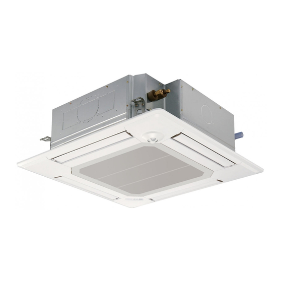
Air-Conditioners For Building Application
PLFY-P VFM-E1
INSTALLATION MANUAL
For safe and correct use, please read this installation manual thoroughly before installing the air-conditioner
unit.
INSTALLATIONSHANDBUCH
Zum sicheren und ordnungsgemäßen Gebrauch der Klimaanlage das Installationshandbuch gründlich durch-
lesen.
MANUEL D'INSTALLATION
Veuillez lire le manuel d'installation en entier avant d'installer ce climatiseur pour éviter tout accident et vous
assurer d'une utilisation correcte.
INSTALLATIEHANDLEIDING
Voor een veilig en juist gebruik moet u deze installatiehandleiding grondig doorlezen voordat u de airconditioner
installeert.
MANUAL DE INSTALACIÓN
Para un uso seguro y correcto, lea detalladamente este manual de instalación antes de montar la unidad de
aire acondicionado.
MANUALE DI INSTALLAZIONE
Per un uso sicuro e corretto, leggere attentamente questo manuale di installazione prima di installare il condiziona-
tore d'aria.
MANUAL DE INSTALAÇÃO
Para segurança e utilização correctas, leia atentamente este manual de instalação antes de instalar a unidade
de ar condicionado.
INSTALLATIONSMANUAL
Læs af sikkerhedshensyn denne installationsmanual grundigt, før du installerer klimaanlægget.
INSTALLATIONSMANUAL
Läs installationsmanualen noga innan du installerar luftkonditioneringsenheten för säker och korrekt an-
vändning.
For sikkert og riktig bruk av klimaanlegget, vennligst les nøye gjennom denne bruksanvisningen før det
installeres.
English (GB)
Deutsch (D)
Français (F)
Nederlands (NL)
Español (E)
Italiano (I)
Português (P)
Dansk (DA)
Svenska (SV)
Norsk (NO)
Polski (PL)
-
Advertisement

Subscribe to Our Youtube Channel
Related Manuals for Mitsubishi Electric PLFY-P VFM-E1


Summary of Contents for Mitsubishi Electric PLFY-P VFM-E1
-
Page 1: Installation Manual
Air-Conditioners For Building Application PLFY-P VFM-E1 INSTALLATION MANUAL English (GB) For safe and correct use, please read this installation manual thoroughly before installing the air-conditioner unit. INSTALLATIONSHANDBUCH Deutsch (D) Zum sicheren und ordnungsgemäßen Gebrauch der Klimaanlage das Installationshandbuch gründlich durch- lesen. - Page 2 Contents 1. Safety precautions ..................2 4. Electrical work ...................6 2. Installing the indoor unit ................2 5. Installing the grille ..................13 3. Refrigerant pipe and drain pipe ..............5 6. Test run ....................17 Note: : Indicates an action that must be avoided. tions”.
-
Page 3: Installing The Indoor Unit
2. Installing the indoor unit 2.2. Ceiling openings and suspension bolt installation (mm) (576) C locations (Fig. 2-2) grille), make an opening in the ceiling so that the main unit can be installed as shown in the diagram. (The method for using the template and the gauge are shown.) * Before using, check the dimensions of template and gauge, because they change due to fluctuations of temperature and humidity. - Page 4 2. Installing the indoor unit Unit Grille Pillow structors and interior decorators should be consulted for details. (1) Extent of ceiling removal: The ceiling must be kept completely horizontal and the ceiling foundation (framework: wooden slats and slat holders) must be reinforced in order to protect the ceiling from vibration.
- Page 5 Drain pipe Ceiling Grille Refrigerant pipe (liquid) Refrigerant pipe (gas) Main unit thickness of 12 mm or more). flare nut. carefully. Warning: ing the compressor. Flare cutting dimensions Copper pipe O.D. Flare dimensions (mm) øA dimensions (mm) ø6.35 ø9.52 ø12.7 16.2 - 16.6 19.3 - 19.7 22.9 - 23.3...
-
Page 6: Band (Large)
1.5~2m more downward slope. Max. 15cm Correct piping Wrong piping Insulation (9 mm or more) Support metal Air bleeder Raised Odor trap Grouped piping O.D. ø32 PVC TUBE Make it as large as possible Indoor unit Make the piping size large for grouped piping. (9 mm or more insulation) 1. - Page 7 Caution: CN4Z junction cables. ■ When using the panel with wireless signal receiver or i-see sensor, install wireless junction cable for connecting with the cable from the panel through the following steps before installing the main unit. CN5Y CN90 i-see sensor: CN5Y (mm) Warning:...
- Page 8 ~220-240V IEC57, 245 IEC 53 or 227 IEC 53. provided by the air conditioner installation. ~220-240V Ground-fault interrupter Indoor unit TB15 Pull box Warning: Never splice the power cable or the indoor-outdoor connection cable, Minimum wire thickness (mm²) Local switch (A) Breaker for wiring Total operating current of the indoor Ground-fault interrupter *1...
- Page 9 1. Wiring transmission cables Types of transmission cable Shielding wire CVVS or CPEVS Types of remote control cable 2-core cable (unshielded) Cable diameter More than 1.25 mm Cable diameter Length Length Types of remote control cable Shielding wire MVVS Cable diameter Length the longest allowable transmission cable indoor unit TB5 is a shielding wire connection.
- Page 10 tion location. SW21-1 SW21-2 Height Silent – 2.5 m Standard 2.7 m : default setting High ceiling With i-See sensor panel, SW3-4 must be adjusted as a position of i-See sensor. (Refer to page 15.) SW3-4 Position 1 Position 3 SW3-5 Draft-less (default) Downward setting...
- Page 11 Vane setting Manual vane angle 1 Select "Maintenance" from the Main Main Main menu No setting Step 1 Step 2 Maintenance Initial setting button. Service Step 3 Step 4 Step 5 Main display: Cursor Page Draft reduction* outlets A screen will appear that indicates the setting information is being 2 Select "Manual vane angle"...
- Page 12 The following settings can be made in the initial setting mode. Item Setting Fig. 4-11 Temperature unit Time display AUTO mode Pair No. Backlight 1. Press the button 1 to stop the air conditioner. 2. Press the button 2. The Function setting screen will be displayed and the function No. A button 3.
-
Page 13: Installing The Grille
5. Installing the grille 5.1. Check the grille accessories (Fig. 5-1) Accessory name Q’ty Remark Grille Screw with washer Gauge Included when equipped with the Junction wire for signal receiver signal receiver. Included when equipped with the Junction wire for i-See sensor When equipped with the signal receiver When equipped with the i-See sensor i-See sensor. -
Page 14: Installing The Grille
5. Installing the grille * Make sure that there are no gaps between the main unit and the grille or the grille A Main unit B Electric component box C Screw with washer (Accessory) D Grille E Ceiling F Make sure that there are no gaps. G Temporary hanging hooks on the panel Caution: When tightening the screw with captive washer C... - Page 15 5. Installing the grille corners of the panel and install them. and signal receiver in the connector box. as shown in the diagram so that there is no slack in the wires, and then cut off the excess end of the fastener. (Fig. 5-13) Fig.
- Page 16 5. Installing the grille The vanes of the unit can be set and locked in up or down orientations depending upon the environment of use. performed using the remote controller. In addition, the actual position of the vanes may differ from the position indicated on the remote controller. Turn off the main power switch.
-
Page 17: Controller Interface
After completing installation and the wiring and piping of the indoor and Warning: Controller interface The following 3 methods are available. Press to save the setting. Press to return to the previous screen. Press to bring up the Main menu. 5 Backlit LCD Operation settings will appear. -
Page 18: Test Run
1 Press the button to go through the operation modes in the order of “Cool” Test run Remain Remain and “Heat”. (Fig. 6-5) Cool mode: Check the cold air blow off. Pipe Heat mode: Check the heat blow off. Cool Auto * Check the operation of the outdoor unit’s fan. - Page 20 (576) C 625 D 576 - 610 C 525 B 570 A 120°...
- Page 23 D E E 30 30...
- Page 24 CN4Z ■ CN5Y CN90...
- Page 25 ~220-240V ~220-240V TB15 6000...
- Page 28 Main Main menu No setting Step 1 Step 2 Maintenance Initial setting Service Step 3 Step 4 Step 5 Main display: Cursor Page Draft reduction* outlets Maintenance menu Auto descending panel Manual vane angle 3D i-See sensor Main menu: Cursor Manual vane angle M-NET address Manual vane angle...
- Page 34 Service menu Test run menu Test run Test run Enter maintenance password Input maintenance info. Drain pump test run Function setting Check Self check Service menu: Select: Cursor Cursor...
- Page 35 Test run Remain Remain Pipe Cool Auto Switch disp. Mode Vane —...
- Page 36 This product is designed and intended for use in the residential, commercial and light-industrial environment. Importer: Mitsubishi Electric Europe B.V. Capronilaan 46, 1119 NS, Schiphol Rijk, The Netherlands French Branch 25, Boulevard des Bouvets, 92741 Nanterre Cedex, France German Branch...
Need help?
Do you have a question about the PLFY-P VFM-E1 and is the answer not in the manual?
Questions and answers