Sony DCR-PC110 Service Manual
Digital video camera recorder
Hide thumbs
Also See for DCR-PC110:
- Operating instructions manual (168 pages) ,
- Operating instructions manual (168 pages)
Table of Contents
Advertisement
DCR-PC110/PC110E
SERVICE MANUAL
SERVICE MANUAL
Level 2
On the VC-253 board
This service manual provides the information that is premised the
circuit board replacement service and not intended repair inside the
VC-253 board.
Therefore, schematic diagram, printed wiring board and electrical parts
list of the VC-253 board are not shown.
The following pages are not shown.
Printed wiring board ......................... Pages 4-11 to 4-14
Schematic diagram .......................... Pages 4-15 to 4-52
Electrical parts list ............................ Pages 6-16 to 6-26
Ver 1.2 2001. 10
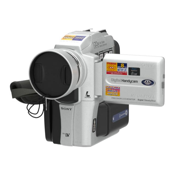
Photo : DCR-PC110
RMT-811
For MECHANISM ADJUSTMENTS, refer to the
"DV MECHANICAL ADJUSTMENT MANUAL
J MECHANISM " (9-929-807-11).
DCR-PC110
DCR-PC110E
SPECIFICATIONS
DIGITAL VIDEO CAMERA RECORDER
RMT-811
US Model
Canadian Model
Korea Model
DCR-PC110
AEP Model
UK Model
Australian Model
Chinese Model
DCR-PC110E
E Model
Hong Kong Model
Tourist Model
DCR-PC110/PC110E
J MECHANISM
: NTSC model
: PAL model
— Continued on next page —
Advertisement
Table of Contents

Subscribe to Our Youtube Channel
Related Manuals for Sony DCR-PC110


Summary of Contents for Sony DCR-PC110
- Page 1 UK Model Australian Model Chinese Model DCR-PC110E E Model Hong Kong Model Tourist Model Photo : DCR-PC110 DCR-PC110/PC110E RMT-811 J MECHANISM For MECHANISM ADJUSTMENTS, refer to the On the VC-253 board “DV MECHANICAL ADJUSTMENT MANUAL This service manual provides the information that is premised the J MECHANISM ”...
- Page 2 MARK 0 ON THE SCHEMATIC DIAGRAMS AND IN THE PARTS CRITIQUES POUR LA SÉCURITÉ DE FONCTIONNEMENT. NE LIST ARE CRITICAL TO SAFE OPERATION. REPLACE THESE REMPLACER CES COMPOSANTS QUE PAR DES PIÈSES SONY COMPONENTS WITH SONY PARTS WHOSE PART NUMBERS DONT LES NUMÉROS SONT DONNÉS DANS CE MANUEL OU APPEAR AS SHOWN IN THIS MANUAL OR IN SUPPLEMENTS DANS LES SUPPÉMENTS PUBLIÉS PAR SONY.
- Page 3 • SUPPLIED ACCESSORIES Check that the following accessories are supplied with your camcorder. Abbreviation HK: Hong Kong model JE: Tourist model — 3 —...
-
Page 4: Table Of Contents
TABLE OF CONTENTS SERVICE NOTE Making your own titles ························································ 1-25 Labeling a cassette ······························································· 1-26 POWER SUPPLY DURING REPAIRS ····························· 7 Customizing Your Camcorder HOW TO OPEN THE FLASH WHEN THE FLASH Changing the menu settings ················································· 1-26 DOESN’T OPEN ······························································· 7 Resetting the date and time ··················································... - Page 5 4-2. PRINTED WIRING BOARDS AND 8 Page Table ··································································· 5-10 SCHEMATIC DIAGRAMS ············································ 4-5 1-2-2. INITIALIZATION OF B PAGE DATA ························· 5-11 • CD-285 (CCD IMAGER) Initializing the B Page Data ··········································· 5-11 PRINTED WIRING BOARD ························· 4-7 Modification of B Page Data ········································· 5-11 •...
- Page 6 Serial No. Input ····························································· 5-40 2-1. Company ID Input ························································· 5-40 2-2. Serial No. Input ····························································· 5-40 Battery End Check (VC-253 board) ······························ 5-42 3-3. SERVO AND RF SYSTEM ADJUSTMENT ··············· 5-43 Cap FG Duty Adjustment (VC-253 Board) ··················· 5-43 PLL f &...
-
Page 7: Service Note
SERVICE NOTE POWER SUPPLY DURING REPAIRS In this unit, about 10 seconds after power is supplied to the battery terminal using the regulated power supply (8.4V), the power is shut off so that the unit cannot operate. This following two methods are available to prevent this. Take note of which to use during repairs. Method 1. -
Page 8: Discharging Of The Flashlight Power
DISCHARGING OF THE FLASHLIGHT POWER SUPPLY CAPACITOR The capacitor (C2010) of the flash unit is charged up to the maximum 300V potential. There is a danger of electric shock by this high voltage when the capacitor is handled by hand. The electric shock is caused by the charged voltage which is kept without discharging when the main power of the unit is simply turned off. -
Page 9: Self-Diagnosis Function
SELF-DIAGNOSIS FUNCTION SELF-DIAGNOSIS FUNCTION SELF-DIAGNOSIS DISPLAY When problems occur while the unit is operating, the counter of the When problems occur while the unit is operating, the self-diagnosis function starts working, and displays on the viewfinder or LCD viewfinder or LCD screen consists of an alphabet and 4-digit screen what to do. -
Page 10: Self-Diagnosis Code Table
SELF-DIAGNOSIS CODE TABLE Self-diagnosis Code Block Detailed Symptom/State Correction Function Code Non-standard battery is used. Use the info LITHIUM battery. Condensation. Remove the cassette, and insert it again after one hour. Video head is dirty. Clean with the optional cleaning cassette. LOAD direction. -
Page 11: General
DCR-PC110/PC110E SECTION 1 This section is extracted from instruction GENERAL manual. (DCR-PC110E model) - Page 20 1-10...
- Page 21 1-11...
- Page 22 1-12...
- Page 23 1-13...
- Page 24 1-14...
- Page 25 1-15...
- Page 26 1-16...
- Page 27 1-17...
- Page 28 1-18...
- Page 29 1-19...
- Page 30 1-20...
- Page 31 1-21...
- Page 32 1-22...
- Page 33 1-23...
- Page 34 1-24...
- Page 35 1-25...
- Page 36 1-26...
- Page 37 1-27...
- Page 38 1-28...
- Page 39 1-29...
- Page 40 1-30...
- Page 41 1-31...
- Page 42 1-32...
- Page 43 1-33...
- Page 44 1-34...
- Page 45 1-35...
- Page 46 1-36...
- Page 47 1-37...
- Page 48 1-38...
- Page 49 1-39...
- Page 50 1-40...
- Page 51 1-41...
- Page 52 1-42...
- Page 53 1-43...
- Page 54 1-44...
- Page 55 1-45...
- Page 56 1-46...
- Page 57 1-47...
- Page 58 1-48...
- Page 59 1-49...
- Page 60 1-50...
- Page 61 1-51...
- Page 62 1-52E...
-
Page 63: Disassembly
DCR-PC110/PC110E SECTION 2 DISASSEMBLY The following flow chart shows the disassembly procedure. PD-134 board service position 2-1. PD-134 board, Inverter transformer unit 2-2. Cabinet (L) block assembly Mechanism deck-(1) service position 2-9. Control switch block (PS30550), Control switch block (FK30550) 2-3. -
Page 64: Board, Inverter Transformer Unit
NOTE: Follow the disassembly procedure in the numerical order given. 2-1. PD-134 BOARD, INVERTER TRANSFORMER UNIT Two screws q; Inverter transformer unit (M1.7 × 2.5), LCD cabinet (R) assembly lock ace, p2 Screw (M1.7 × 2.5), 3 Remove the 2 Two claws three solderings lock ace, p2 1 Harness... -
Page 65: Cabinet (L) Block Assembly
2-2. CABINET (L) BLOCK ASSEMBLY Cabinet (upper) Screw 5 Push the lock plate in the (M1.7 × 4), direction of the arrow B Routing of the flexible board of the Operation lock ace, p2 to open the flash unit. 2 Two claws switch block (FK30550) when attaching the Lock plate Cabinet (L) block. -
Page 66: Evf Block Assembly
2-3. EVF BLOCK ASSEMBLY 3 FP-252 flexible board (10P) 2 FP-253 flexible board (33P) 4 EVF block assembly 1 Screw (M1.7 × 2.5), lock ace, p2 7 Lens holder assembly 4 EVF cup assembly 6 LCD cushion (B) 5 Light guide plate block, 3 VF spacer BL cushion (B), BL holder... -
Page 67: Vtr Overall Section
2-4. VTR OVERALL SECTION, CABINET (R) BLOCK ASSEMBLY 7 Cabinet (R) block assembly 5 FP-255 flexible board (27P) Screw Screw (M1.7 × 2.5), (M1.7 × 2.5), lock ace, p2 lock ace, p2 Two screws FJ-027 board (70P) (M1.7 × 2.5), lock ace, p2 VTR overall section 2-5. -
Page 68: Board
2-6. FJ-027 BOARD 2 CPC lid Screw (M1.7 × 2.5), lock ace, k3 qa FP-251 flexible board qd FJ-027 board (6P) qs Harness (PT-107) (6P) Battery Terminal board Terminal retainer Screw (M1.7 × 2.5), lock ace, p2 9 DC frame Two screws 0 DC-IN connector (M1.7 ×... -
Page 69: Boards, Mechanism Deck
2-8. AI-021, VC-253 BOARDS, MECHANISM DECK Two screws Two screws (M1.7 × 2.5), (M1.7 × 2.5), lock ace, p2 lock ace, p2 7 Cassette compartment cover 8 Mechanism deck, 2 AI-021 board (100P) MD frame assembly, MK sheet metal 4 FP-256 flexible board Three screws 5 VC-253 board (M1.7 ×... -
Page 70: Control Switch Block (Ps30550), Control Switch Block (Fk30550)
2-9. CONTROL SWITCH BLOCK (PS30550), CONTROL SWITCH BLOCK (FK30550) Screw Screw (M1.7 × 2.5), Screw (M1.7 × 4), (M1.7 × 4), lock ace, p2 lock ace, p2 lock ace, p2 3 Control switch block (FK30550) (17P) 7 Precision screw (dia, 1.7 × 4) q;... -
Page 71: Lcd Hinge Assembly
2-10.LCD HINGE ASSEMBLY 5 Blind plate assembly Remove it while taking care so that it must not be caught by the flexible board and harnesses, by pulling it in the direction of the arrow. 2 FP-251 flexible board Two screws (M1.7 ×... -
Page 72: Circuit Boards Location
2-11.CIRCUIT BOARDS LOCATION VF-147 (LCD DRIVE, BACK LIGHT) AI-021 AUDIO PROCESSOR, LINE IN/OUT PD-134 (RGB DRIVE, TIMING GENE.) FP-256 (SIRCS/IR) INVERTER TRANSFORMER UNIT FJ-027 (DC IN) CD-285 (CCD IMAGER) FLASH UNIT (MC) VC-253 CAMERA, REC/PB HEAD AMP, HI CONTROL, MECHA CONTROL, SERVO, MS INTERFACE, DC-DC CONVERTER, Y/C PROCESSOR 2-10... -
Page 73: Flexible Boards Location
2-12.FLEXIBLE BOARDS LOCATION The flexible boards contained in the mechanism deck and that in the lens device are not shown. CONTROL SWITCH BLOCK FP-253 CONTROL SWITCH BLOCK (PS30550) (FK30550) CONTROL SWITCH BLOCK (MF30550) CONTROL SWITCH BLOCK FP-252 FLASH UNIT (ST) (ME30550) FP-255 FP-251... -
Page 74: Block Diagrams
DCR-PC110/PC110E SECTION 3 BLOCK DIAGRAMS 3-1. OVERALL BLOCK DIAGRAM (1/3) ( ) : Page No. shown in ( ) indicates the page to refer on the schematic diagram. CD-285 BOARD VC-253 BOARD(1/3) IC1902 CN651 IC101 SPCK1 (4-22) (4-17) LENS ASSY... -
Page 75: Overall Block Diagram (2/3)
DCR-PC110/PC110E 3-2. OVERALL BLOCK DIAGRAM (2/3) ( ) : Page No. shown in ( ) indicates the page to refer on the schematic diagram. CN263 J MECHA DECK FOR ADJUSTMENTS (SEE PAGE 4-40,85) (4-28) VC-253 BOARD(2/3) RF MON IC952 REC CK... -
Page 76: Overall Block Diagram (3/3)
DCR-PC110/PC110E 3-3. OVERALL BLOCK DIAGRAM (3/3) ( ) : Page No. shown in ( ) indicates the page to refer on the schematic diagram. CN263 FOR ADJUSTMENTS FP-251(FLEXIBLE) CN253 CONTROL SWITCH VC-253 BOARD(3/3) PANEL REV S001 (PANEL REVERSE) BLOCK(ME-30550) (SEE PAGE 4-84) -
Page 77: Power Block Diagram (1/2)
DCR-PC110/PC110E 3-4. POWER BLOCK DIAGRAM (1/2) ( ) : Page No. shown in ( ) indicates the page to refer on the schematic diagram. CN1333 CN253 J1332 LANC DC SHOE ON LANC SHOE UNREG SHOE UNREG BATT SIG 33,36 33,36... -
Page 78: Power Block Diagram (2/2)
DCR-PC110/PC110E 3-5. POWER BLOCK DIAGRAM (2/2) ( ) : Page No. shown in ( ) indicates the page to refer on the schematic diagram. AI-021 BOARD VC-253 BOARD(2/2) CONTROL SWITCH VTR UNREG BLOCK(FK30550) IC001 IC002 IC1061 IC404 (4-36) (XYZ) AUDIO ADC&... -
Page 79: Printed Wiring Boards And Schematic Diagrams
DCR-PC110/PC110E SECTION 4 PRINTED WIRING BOARDS AND SCHEMATIC DIAGRAMS 4-1. FRAME SCHEMATIC DIAGRAM (1/2) IMAGER LENS-ASSY CONTROL SWITCH BLOCK FLASH UNIT (ME-30550) (30550ST) CD-285 S2101 OPEN/CLOSE BOARD S1801-S1820 VOLUME+/VOLUME-/DISPLAY/ END SEARCH/MEMORY PLAY/MEMORY/INDEX/ MPEG /PB ZOOM/REW/MEMORY DELETE/ MEMORY MIX/MEMORY+/MEMORY-/ TITLE/DIGITAL EFFECT/PLAY/FF/... -
Page 80: Frame Schematic Diagram (1/2)
DCR-PC110/PC110E FRAME SCHEMATIC DIAGRAM (2/2) MIC901 VC-253 BOARD CN1061 CN951 AI-021 BOARD INT MIC L 1/19 CH BLOCK 10/19 LD BLOCK MIC L INT MIC GND YSDL YSDL 2/19 CA BLOCK 11/19 HI BLOCK 1/3 LINE IN/OUT 2/3 AUDIO IN/OUT... -
Page 81: Printed Wiring Board
DCR-PC110/PC110E DCR-PC110/PC110E 4-2. PRINTED WIRING BOARDS AND SCHEMATIC DIAGRAMS THIS NOTE IS COMMON FOR WIRING BOARDS AND SCHEMATIC DIAGRAMS (In addition to this, the necessary note is printed in each block) (For printed wiring boards) (Measuring conditions voltage and waveform) •... - Page 82 DCR-PC110/PC110E CD-285 (CCD IMAGER) PRINTED WIRING BOARD — Ref. No. CD-285 Board; 20,000 Series — For printed wiring board • Refer to page 4-92 for parts location. • CD-285 board consists of multiple layers. However, only the sides (layers) A and B are shown.
-
Page 83: Control Switch Block (Mf30550)
DCR-PC110/PC110E For Schematic Diagram • Refer to page 4-88 for waveforms. CD-285 BOARD NO MARK:REC/PB MODE R :REC MODE CCD IMAGER P :PB MODE * :Cannot measure -REF.NO.:20000 SERIES- XX MARK:NO MOUNT R1264 Q1253 Q1252 NDS356AP 2SC4250(T5LSONY1) L1251 C1251 C1278... - Page 84 Schematic diagram and printed wiring board of the VC-253 board are not shown. Pages from 4-11 to 4-52 are not shown.
-
Page 85: Line In/Out)
DCR-PC110/PC110E For Schematic Diagram • Refer to page 4-59 for printed wiring board. • Refer to page 4-88 for waveforms. AI-021 BOARD(1/3) LINE IN/OUT -REF.NO.:20000 SERIES- XX MARK:NO MOUNT A_4.6V NO MARK:REC/PB MODE FB551 TO(3/3) D_2.8V L551 C562 L552 L554... -
Page 86: Audio In/Out, Dac/Adc
DCR-PC110/PC110E For Schematic Diagram • Refer to page 4-59 for printed wiring board. AI-021 BOARD(2/3) AUDIO IN/OUT R041 R039 D1052 D1055 D1051 D1053 D1054 -REF.NO.: 20000 SERIES- 01ZA8.2(TPL3) 01ZA8.2(TPL3) 01ZA8.2(TPL3) 01ZA8.2(TPL3) 01ZA8.2(TPL3) MIC_L XX MARK:NO MOUNT TO(3/3) MIC_R R040 NO MARK:REC/PB MODE... - Page 87 DCR-PC110/PC110E For Schematic Diagram • Refer to page 4-59 for printed wiring board. AI-021 BOARD(3/3) CN1055 100P MIC AMP AU_GND AU_GND AU_GND AU_GND -REF.NO.:20000 SERIES- C1100 C1099 TO(1/3) D_2.8V A_4.6V A_4.6V TO(1/3) R1061 R1062 D_2.8V 0.1u 0.1u XX MARK:NO MOUNT AU_4.6V...
-
Page 88: Audio Processor, Line In/Out
DCR-PC110/PC110E AI-021 (AUDIO PROCESSOR, LINE IN/OUT) PRINTED WIRING BOARD — Ref. No. AI-021 Board; 20,000 Series — For printed wiring board VF-147 (LCD DRIVE, BACK LIGHT) AI-021 • Refer to page 4-92 for parts location. AUDIO PROCESSOR, • AI-021 board consists of multiple layers. However, only LINE IN/OUT PD-134 (RGB DRIVE, TIMING GENE.) - Page 89 DCR-PC110/PC110E AUDIO PROCESSOR, LINE IN/OUT 4-61 4-62 AI-021...
- Page 90 DCR-PC110/PC110E FB1731 J1733 FB1732 CONTROL SWITCH BLOCK (PLUG IN POWER) FB1733 (FK-30550) LND1737 R1737 C1731 C1732 CN1733 SHASSIS GND 0.001u 0.001u -REF.NO.:50000 SERIES- REG_GND XX MARK:NO MOUNT EXT_MIC_L NO MARK:REC/PB MODE J1732 R1734 EXT_MIC_R FB1734 8200 EXT_MIC_GND FB1737 (HEADPHONES) HP_GND...
- Page 91 DCR-PC110/PC110E CONTROL SWITCH BLOCK (FK-30550) PRINTED WIRING BOARD — Ref. No. Control switch block (FK-30550) Board; 50,000 Series — CONTROL SWITCH BLOCK CONTROL SWITCH BLOCK (FK-30550) (SIDE A) (FK-30550) (SIDE B) CONTROL SWITCH BLOCK(ME-30550) -REF.NO.:50000 SERIES- XX MARK:NO MOUNT R1833...
-
Page 92: Control Switch Block Ps30550
DCR-PC110/PC110E FP-256 FLEXIBLE BOARD CONTROL SWITCH BLOCK(PS-30550) NO MARK:REC/PB MODE -REF.NO.:30000 SERIES- XX MARK:NO MOUNT -REF.NO.:50000 SERIES- XX MARK:NO MOUNT NO MARK:REC/PB MODE CN1771 F1701 0.2A REG_GND A_4.6V KEY_AD2 C1702 XF_TALLY_LED D1703 DIAL_A SIRCS_SIG DCR2815 S1777 Q1701 (SELF TIMER) SCHARGE_LED... -
Page 93: Flash Unit 30550Mc/30550St
DCR-PC110/PC110E FLASH UNIT(30550MC) -REF.NO.:50000 SERIES- Q2002 XX MARK:NO MOUNT L2001 CPH3109-TL LND201 STATIC_GND D2001 2.2uH NO MARK:REC/PB MODE MA111-(K8).S0 C2007 CN2001 LND202 STATIC_GND R2010 T2001 R2003 ST_GND 100k 2012 ST_GND R2019 ST_GND Q2001-2003, HIGH VOLTAGE CHARGER FLASH UNIT(30550ST) R2005 Q2003... -
Page 94: Printed Wiring Board
DCR-PC110/PC110E PD-134 (RGB DRIVE, TIMING GENE) PRINTED WIRING BOARD — Ref. No. PD-134 Board; 40,000 Series — For printed wiring board VF-147 (LCD DRIVE, BACK LIGHT) AI-021 • Refer to page 4-93 for parts location. AUDIO PROCESSOR, • PD-134 board consists of multiple layers. However, only LINE IN/OUT PD-134 (RGB DRIVE, TIMING GENE.) - Page 95 DCR-PC110/PC110E For Schematic Diagram • Refer to page 4-88 for waveforms. PD-134 BOARD L2103 R2161 R2165 C2115 10uH C2112 Q2104 3.3u 2520 2.2u RGB DRIVE,TIMING GENE. NDS356AP 2012 B+ SWITCH 13.5 13.5 C2114 -REF.NO.:40000 SERIES- C2130 R2114 0.01u R2144 0.01u...
-
Page 96: Lcd Drive, Back-Light
DCR-PC110/PC110E VF-147 (LCD DRIVE, BACK-LIGHT) PRINTED WIRING BOARD — Ref. No. VF-147 Board; 20,000 Series — For printed wiring board VF-147 (LCD DRIVE, BACK LIGHT) AI-021 • Refer to page 4-93 for parts location. AUDIO PROCESSOR, • VF-147 board consists of multiple layers. However, only LINE IN/OUT the sides (layers) A and B are shown. -
Page 97: Lcd Drive, Back-Light
DCR-PC110/PC110E For Schematic Diagram • Refer to page 4-88 for waveforms. VF-147 BOARD LCD DRIVE,BACK-LIGHT -REF.NO.:20000 SERIES- XX MARK:NO MOUNT L1433 NO MARK:REC/PB MODE 10uH CN1402 C1442 Note : Note : SHOE_UNREG 3.3u SHOE_UNREG The components identified by Les composants identifiés par... -
Page 98: Dc-In
DCR-PC110/PC110E FJ-027 (DC-IN) PRINTED WIRING BOARD — Ref. No. FJ-027 Board; 20,000 Series — For printed wiring board • Refer to page 4-93 for parts location. • FJ-027 board consists of multiple layers. However, only the sides (layers) A and B are shown. - Page 99 DCR-PC110/PC110E DC-IN 4-81 4-82 FJ-027...
-
Page 100: Flexible Boards
DCR-PC110/PC110E For Schematic Diagram • Refer to page 4-79 for printed wiring board. FP-251 FJ-027 BOARD FLEXIBLE DC-IN,CHARGE BOARD NO MARK:REC/PB MODE S002 -REF.NO.:20000 SERIES- CN1332 (PANEL OPEN) XX MARK:NO MOUNT PANEL OPEN FB1333 J1332 S001 (PANEL REVERSE) LANC_DC PANEL_REV... - Page 101 DCR-PC110/PC110E FP-100 (MODE SWITCH), FP-228 (DEW SENSOR), FP-102 (TAPE TOP/END SENSOR, S/T REEL) FLEXIBLE BOARDS — Ref. No. FP-100, 102, 228 Flexible Board; 50,000 Series — Q902 TAPE TOP SENSOR FP-102 FLEXIBLE BOARD 1-677-085- D901 S903 (CC DOWN) (TAPE LED)
-
Page 102: Waveforms
DCR-PC110/PC110E DCR-PC110/PC110E 4-3. WAVEFORMS PD-134/VF-147 CD-285 AI-021 BOARD BOARD BOARD REC/PB REC/PB IC1252 9 CAMERA REC IC2101 rh/IC1431 rh IC2103 rk/IC1432 rk IC551 7 2.9Vp-p 5.0Vp-p 500mVp-p 30 nsec 370mVp-p IC1252 qs,qd CAMERA REC IC2101 rj/IC1431 rj IC551 qf (S-VIDEO OUT) 4.0Vp-p... - Page 103 Waveforms and parts location of the VC-253 board are not shown. Pages from 4-89 to 4-91 are not shown.
-
Page 104: Mounted Parts Location
DCR-PC110/PC110E 4-4. MOUNTED PARTS LOCATION CD-285 BOARD (SIDE A) AI-021 BOARD (SIDE A) AI-021 BOARD (SIDE B) CN1251 F-4 C551 Q551 C001 CN1055 B-11 R1061 A-10 C554 C002 CN1061 A-11 R1062 A-10 IC1251 F-1 C555 R551 C003 R1063 B-10 C556... - Page 105 DCR-PC110/PC110E PD-134 BOARD (SIDE A) VF-147 BOARD (SIDE A) FJ-027 BOARD (SIDE A) C2101 Q2108 B-1 C1431 R1438 A-9 C1331 Q1336 B-5 C2102 Q2109 B-3 C1432 R1439 B-9 C1339 Q1337 B-5 C2103 Q2111 C-2 C1438 R1440 A-9 C1340 C2104 Q2112 B-3...
-
Page 106: Adjustments
DCR-PC110/PC110E SECTION 5 ADJUSTMENTS Before starting adjustment EVR Data Re-writing Procedure When Replacing Board The data that is stored in the repair board, is not necessarily correct. Perform either procedure 1 or procedure 2 or procedure 3 when replacing board. -
Page 107: Adjusting Items When Replacing Main Parts And Boards
1-1. Adjusting items when replacing main parts and boards. • Adjusting items when replacing main parts When replacing main parts, adjust the items indicated by z in the following table. Note1: When replacing the drum assy. or the mechanism deck, reset the data of page: 2, address: A2 to A4 to “00”. (Refer to “Record of Use check” of “5- 4. - Page 108 • Adjusting items when replacing a board or EEPROM When replacing a board or EEPROM, adjust the items indicated by z in the following table. Board replacement Adjustment Adjustment Section Initialization Initialization of C,D,8 page data of B,C,D,E,F, Initialization of B page data 7,8 page data Initialization of E,F,7 page data 54MHz/66MHz origin oscillation adj.
-
Page 109: Camera Section Adjustment
5-1. CAMERA SECTION ADJUSTMENT 1-1. PREPARATIONS BEFORE ADJUSTMENT (CAMERA SECTION) 1-1-1. List of Service Tools • Oscilloscope • Color monitor • Vectorscope • Regulated power supply • Digital voltmeter Ref. No. Name Parts Code Usage Auto white balance adjustment/check Filter for color temperature correction (C14) J-6080-058-A White balance adjustment/check ND filter 1.0... -
Page 110: Preparations
1-1-2. Preparations Note 1: For details of how remove the cabinet and boards, refer to “2. DISASSEMBLY”. Note 2: When performing only the adjustments, the lens block and boards Pattern box need not be disassembled. Connect the equipment for adjustments according to Fig. 5-1-3. Note 3: As removing the cabinet (L) (removing CN1054 of AI-021 board) means removing the lithium 3V power supply (BT1731), data such as date, time, user-set menus will be lost. - Page 111 Vector scope Color monitor Cabinet (L) VIDEO (Yellow) Terminated at 75 Ω Audio L AUDIO/VIDEO (White) jack VF-147 board Audio R (Red) CN1401 CN1402 Must be connected when performing Need not be the color EVF adjustments. connected. Must be connected. Must be connected when using...
-
Page 112: Precaution
1-1-3. Precaution 1. Setting the Switch Unless otherwise specified, set the switches as follows and perform adjustments without loading cassette. POWER switch (PS-30550 block) ......CAMERA 16 : 9 WIDE (Menu setting) ..........OFF NIGHT SHOT switch (Lens block) ......... OFF PICTURE EFFECT (Menu setting) ......... -
Page 113: Initialization Of C, D, 8 Page Data
1-2. INITIALIZATION OF B, C, D, E, F, 7, 8 PAGE Processing after Completing Modification of C, D, 8 Page data DATA Order Page Address Data Procedure Set the data 1-2-1. INITIALIZATION OF C, D, 8 PAGE DATA Set the data, and press the PAUSEbutton. - Page 114 Address Remark Address Remark Initial value Initial value Fixed data-1 Serial No. input Fixed data-2 (Modified data. Copy the data built in the same model.) 8A to 9A Fixed data-1 Fixed data-2 Fixed data-1 Fixed data-2 F0 to F3 Fixed data-1 (Modified data.
-
Page 115: Page Table
4. D Page Table Initial value Address Remark Note: Fixed data-1: Initialized data. (Refer to “1. Initializing the C, D, 8 NTSC PAL Page Data”.) D8 to D9 Fixed data-1 Fixed data-2: Modified data. (Refer to “2. Modification of C, D, 8 Page Data”.) Fixed data-2 DB to FF... - Page 116 1-2-2. INITIALIZATION OF B PAGE DATA Processing after Completing Modification of B Page data: Order Page Address Data Procedure Note: When reading the B page data, insert a “Memory Stick” into the Set the data. “Memory Stick” slot. Switch setting: Set the data, and press PAUSE POWER ..............
- Page 117 20 to 2F Fixed data-1 Set the data. AWB & LV standard data input Set the following data, and press PAUSE button. 2D: DCR-PC110 (NTSC) 2F: DCR-PC110E (PAL) Fixed data-1 Set the data, and press PAUSE Color reproduction adj. button.
- Page 118 4. E Page Table Initial value Address Remark Note1: Fixed data-1: Initialized data. (Refer to “1. Initializing the E, F, 7 NTSC PAL Page Data”.) Flange back adj. Fixed data-2: Modified data. (Refer to “2. Modification of E, F, 7 Page Data”.) Address Remark...
-
Page 119: Page Table
5. 7 Page Table Initial value Address Remark Note1: Fixed data-1: Initialized data. (Refer to “1. Initializing the E, F, 7 NTSC PAL Page Data”.) CB to CE Fixed data-1 Fixed data-2: Modified data. (Refer to “2. Modification of E, F, 7 Page Data”.) Fixed data-2 Initial value... -
Page 120: Camera System Adjustments
1-3. CAMERA SYSTEM ADJUSTMENTS Before perform the camera system adjustments, check that the specified values of “VIDEO SYSTEM ADJUSTMENT” are satisfied. Note: NTSC model: DCR-PC110 PAL model: DCR-PC110E 1. 54MHz/66MHz Origin Oscillation Adjustment 2. Zoom Key Center Adjustment (CD-285 board) Set the frequency of the clock for synchronization. -
Page 121: Hall Adjustment
Ver 1.1 2000. 10 3. HALL Adjustment Processing after Completing Adjustments: Order Page Address Data Procedure For detecting the position of the lens iris and ND filter, adjust AMP Set the data. gain and offset. Set the data. Subject Not required Set the data, and press PAUSE Measurement Point Display data of page 1 (Note1) -
Page 122: Mr Adjustment
4. MR Adjustment The MR (Magnet resistor) adjustment of the inner focus lens is carried out automatically. In whichever case, the focus will be deviated during auto focusing/manual focusing. Subject Not required Measurement Point Adjustment remote commander Measuring Instrument Adjustment Page Adjustment Address 50 to 59, 62 Specified Value1... -
Page 123: Flange Back Adjustment (Using Minipattern Box)
5. Flange Back Adjustment (Using Minipattern Box) The inner focus lens flange back adjustment is carried out automatically. In whichever case, the focus will be deviated during auto focusing/manual focusing. Subject Siemens star chart with ND filter for the minipattern box (Note1) Measurement Point Display data of page: F, address: 63 Measuring Instrument... -
Page 124: More Than 500M Away
6. Flange Back Adjustment (Using Flange Back Adjustment Chart and Subject More Than 500m Away) The inner focus lens flange back adjustment is carried out automatically. In whichever case, the focus will be deviated during auto focusing/manual focusing. 6-1. Flange Back Adjustment (1) 6-2. -
Page 125: Flange Back Check
7. Flange Back Check 8. Picture Frame Setting Subject Siemens star Subject Color bar chart (2.0m from the front of the lens) (Color reproduction adjustment (Luminance : approx. 200 lux) frame) (1.5m from the front of the lens) Measurement Point Check operation on TV monitor Measurement Point Video output terminal... -
Page 126: Color Reproduction Adjustment
35, 37, 3C, 3D Specified Value All color luminance points should settle within each color reproduction frame. For NTSC model Note: NTSC model: DCR-PC110 PAL model: DCR-PC110E Switch setting: POWER ..............CAMERA NIGHT SHOT ..............OFF DIGITAL ZOOM (Menu display) ........OFF STEADY SHOT (Menu display) ........ -
Page 127: Max Gain Adjustment
Note4: Displayed data of page 1 of the adjustment remote commander. Set the data. 1 : XX : XX Display data Set the following data. 18: DCR-PC110 (NTSC) Switch setting: 0C: DCR-PC110E (PAL) 1) POWER ..............CAMERA Set the data, and press PAUSE 2) NIGHT SHOT .............. - Page 128 12. Auto White Balance Adjustment Adjusting method: Adjust to the proper auto white balance output data. Order Page Address Data Procedure If it is not correct, auto white balance and color reproducibility will Place the C14 filter for color be poor. temperature correction on the Subject Clear chart...
-
Page 129: White Balance Check
13. White Balance Check Processing after Completing Adjustments Order Page Address Data Procedure Subject Clear chart (Color reproduction adjustment Set the data, and press PAUSE frame) button. Filter Filter C14 for color temperature Set the data. correction Set the data. ND filter 1.0 and 0.4 and 0.1 Measurement Point Video output terminal... -
Page 130: Mechanical Shutter Data Input
14. Mechanical Shutter Data Input 15. Angular Velocity Sensor Sensitivity Adjustment • This adjustment is performed only when replacing the angular velocity sensor. Adjustment Page Although this adjustment need not be performed when the circuit Adjustment Address 70 to 84 1D to 20 is damaged, etc., check the operations. -
Page 131: Strobe Light Level Adjustment
16. Strobe Light Level Adjustment 17. Strobe Light Level Adjustment for Movie Mode Adjust the light level when the strobe light flashes. Adjust the light level when the strobe light flashes twice. Subject Paper which reflection rate is 18% Subject Paper which reflection rate is 18% (1.0m from the front of the lens)(Note1) (1.0m from the front of the lens)(Note1) -
Page 132: Strobe White Balance Adjustment & Check
18. Strobe White Balance Adjustment & Check Adjusting method: Adjust and check the white balance when the strobe light flashes. Order Page Address Data Procedure Subject Paper which reflection rate is 18% Set the data. (1.0m from the front of the lens)(Note1) Set the data. -
Page 133: Color Electronic Viewfinder System
[Adjusting connector] f = 15625 ± 30Hz (PAL) Most of the measuring points for adjusting the viewfinder system are concentrated in CN263 of the VC-253 board. Note1: NTSC: DCR-PC110 Connect the Measuring Instruments via CPC-8 terminal board jig PAL: DCR-PC110E (J-6082-388-A). -
Page 134: Bright Adjustment (Vf-147 Board)
2. Bright Adjustment (VF-147 board) 3. Contrast Adjustment (VF-147 board) Set the D range of the RGB decoder used to drive the LCD to the Set the level of the VIDEO signal for driving the LCD to the specified specified value. If deviated, the LCD screen will become blackish value. -
Page 135: White Balance Adjustment (Vf-147 Board)
4. White Balance Adjustment (VF-147 board) Correct the white balance. If deviated, the reproduction of the EVF screen may degenerate. Mode Camera Subject Arbitrary Measurement Point Check on EVF screen Measuring Instrument Adjustment Page Adjustment Address 97, 98 Specified Value The EVF screen should not be colored. -
Page 136: Lcd System Adjustment
Pin No. and signal name of CN2105. Specified Value f = 15734 ± 30Hz (NTSC) f = 15625 ± 30Hz (PAL) Pin No. Signal Name Note1: NTSC: DCR-PC110 PAL: DCR-PC110E Adjusting method: PSIG Order Page Address Data Procedure Set the data. -
Page 137: Bright Adjustment (Pd-134 Board)
Change the data and set the Set the data. voltage (A) between the reversed Set the following data. waveform pedestal and non- 5B: DCR-PC110 (NTSC) reversed waveform pedestal to 53: DCR-PC110E (PAL) the specified value. Change the data and set the Press PAUSE button. -
Page 138: Contrast Adjustment (Pd-134 Board)
4. Contrast Adjustment (PD-134 board) 5. Center Level Adjustment (PD-134 board) Set the level of the VIDEO signal for driving the LCD to the specified Set the video signal center level of LCD panel to an appropriate value. If deviated, the screen image will be blackish or saturated level. -
Page 139: V-Com Adjustment (Pd-134 Board)
6. V-COM Adjustment (PD-134 board) 7. White Balance Adjustment (PD-134 board) Set the DC bias of the common electrode drive signal of LCD to the Correct the white balance. specified value. If deviated, the reproduction of the LCD screen may degenerate. If deviated, the LCD display will move, producing flicker and Mode VTR stop... -
Page 140: Mechanism Section Adjustment
5-2. MECHANISM SECTION ADJUSTMENT On the mechanism section adjustment 2-3. TAPE PATH ADJUSTMENT For details of mechanism section adjustments, checks, and replacement of mechanism parts, refer to the separate Note: The lens block (CD-285 board) must be connected when performing volume “DV MECHANICAL ADJUSTMENT MANUAL the adjustments. -
Page 141: Video Section Adjustments
5-3. VIDEO SECTION ADJUSTMENTS NTSC model : DCR-PC110 PAL model : DCR-PC110E 3-1. PREPARATIONS BEFORE ADJUSTMENTS Use the following measuring instruments for video section adjustments. 3-1-1. Equipment Required 1) TV monitor 2) Oscilloscope (dual-phenomenon, band above 30 MHz with delay mode) (Unless specified otherwise, use a 10 : 1 probe.) 3) Frequency counter 4) Pattern generator with video output terminal. -
Page 142: Precautions On Adjusting
3-1-2. Precautions on Adjusting Note 1: Setting the “Forced VTR Power ON” mode (VTR mode) 1) Select page: 0, address: 01, and set data: 01. 2) Select page: D, address: 10, set data: 02, and press the PAUSE The adjustments of this unit are performed in the VTR mode button of the adjustment remote commander. -
Page 143: Adjusting Connectors
3-1-3. Adjusting Connectors Some of the adjusting points of the video section are concentrated at VC-253 board CN263. Connect the measuring instruments via the CPC-8 jig (J-6082-388-A). The following table lists the pin numbers and signal names of CN263. Pin No. Signal Name Pin No. -
Page 144: Alignment Tapes
3-1-5. Alignment Tapes Use the alignment tapes shown in the following table. Use tapes specified in the signal column of each adjustment. Name Tracking standard (XH2-1) Tape path adjustment SW/OL standard (XH2-3) Switching position adjustment Audio operation check Audio system adjustment (XH5-3 (NTSC), XH5-3P (PAL)) System operation check Operation check... -
Page 145: System Control System Adjustment
3-2. SYSTEM CONTROL SYSTEM ADJUSTMENT 2-2. Serial No. Input Write the serial No. and model code in the EEPROM (nonvolatile memory). Convert the serial No. on the name plate from decimal to 1. Initialization of B, C, D, E, F, 7, 8 Page Data hexadecimal, and write in the EEPROM. - Page 146 Hexa- Hexa- Hexa- Hexa- Hexa- Hexa- Hexa- Hexa- Decimal Decimal Decimal Decimal Decimal Decimal Decimal Decimal decimal decimal decimal decimal decimal decimal decimal decimal 0000 8192 2000 16384 4000 24576 6000 32768 8000 40960 A000 49152 C000 57344 E000 0100 8448 2100 16640...
-
Page 147: Battery End Check (Vc-253 Board)
3. Battery End Check (VC-253 board) Check the battery end voltage. Mode Camera recording and VTR playback Subject Arbitrary Note: It is normal though the following symptoms appear during the battery end check. 1) The message of “FOR InfoLITHIUM BATTERY ONLY” on the LCD or viewfinder screen. -
Page 148: Servo And Rf System Adjustment
3-3. SERVO AND RF SYSTEM ADJUSTMENT 2. PLL f & LPF f Adjustment (VC-253 Board) Before perform the servo and RF system adjustments, check that the specified value of “54MHz/66MHz Origin Oscillation Mode VTR stop Adjustment” of “CAMERA SYSTEM ADJUSTMENT” is satisfied. Measurement Point Display data of page: 3, address: 03 Measuring Instrument... -
Page 149: Switching Position Adjustment (Vc-253 Board)
3. Switching Position Adjustment (VC-253 Board) 4. AGC Center Level and APC & AEQ Adjustment 4-1. Preparations before adjustments Mode VTR playback Mode Camera recording Signal SW/OL reference tape (XH2-3) Subject Arbitrary Measurement Point Display data of page: 3, address: 03 Measuring Instrument Adjustment remote commander Adjusting method:... -
Page 150: Apc & Aeq Adjustment (Vc-253 Board)
4-3. APC & AEQ Adjustment (VC-253 Board) 4-4. Processing after Completing Adjustments Order Page Address Data Procedure Mode Playback Signal Recorded signal at “Preparations Set the data. before adjustments” Set the data. Measurement Point Pin w; of CN263 (RF MON) (Note 1) Set the data. -
Page 151: Pll F & Lpf F
5. PLL f & LPF f Final Adjustment (VC-253 Board) Mode VTR stop Measurement Point Display data of page: 3, address: 03 Measuring Instrument Adjustment remote commander Adjustment Page Adjustment Address 1F, 20, 22, 29 Specified Value Bit2, bit3 and bit6 are “0” Adjusting method: Order Page Address Data Procedure... -
Page 152: Video System Adjustments
3-4. VIDEO SYSTEM ADJUSTMENTS 2. S VIDEO OUT Y Level Adjustment (VC-253 Board) Before perform the video system adjustments, check that the specified value of “54MHz/66MHz Origin Oscillation Adjustment” Mode Camera of “CAMERA SYSTEM ADJUSTMENT” is satisfied. Subject Arbitrary Measurement Point Y signal terminal of S VIDEO jack Note: The lens block (CD-285 board) must be connected when performing (75Ω... -
Page 153: S Video Out Chroma Level Adjustment
3. S VIDEO OUT Chroma Level Adjustment 4. VIDEO OUT Y, Chroma Level Check (VC-253 Board) (VC-253 Board) Mode Camera Mode Camera Subject Arbitrary Subject Arbitrary Measurement Point VIDEO terminal of AUDIO/VIDEO Measurement Point Chroma signal terminal of S VIDEO jack (75Ω... -
Page 154: Ir Video Carrier Frequency Adjustment (Vc-253 Board)
3-5. IR TRANSMITTER ADJUSTMENTS Adjust using a IR receiver jig (J-6082-383-A). Switch setting: LASER LINK ........ON (Red LED is lit) 1. IR Video Carrier Frequency Adjustment (VC-253 board) 2. IR Video Deviation Adjustment (VC-253 board) Mode VTR stop Mode VTR stop Signal Arbitrary... -
Page 155: Ir Audio Deviation Adjustment (Vc-253 Board)
3. IR Audio Deviation Adjustment (VC-253 board) Mode VTR stop Signal Video : No signal Audio : 400Hz, –7.5dBs, Audio left and right terminal of AUDIO/VIDEO jack Measurement Point AUDIO L terminal and AUDIO R terminal of IR receiver jig (Terminated at 47kΩ) Measuring Instrument Audio level meter... -
Page 156: Audio System Adjustments
3-6. AUDIO SYSTEM ADJUSTMENTS [Connection of Audio System Measuring Devices] Connect the audio system measuring devices as shown in Fig. 5-3-15. Main unit Recording (Camera mode) 600 Ω Left Audio oscillator Right Attenuator 600 Ω : 270 Ω (1-249-410-11) + 330 Ω (1-249-411-11) Playback Main unit TV monitor... -
Page 157: Playback Level Check
1. Playback Level Check 4. Overall Noise Level Check Mode VTR playback Mode Camera recording and playback Signal Alignment tape: Signal No signal: Insert a shorting plug in the For audio operation check MIC jack (XH5-3 (NTSC)) Measurement Point Audio left or right terminal of AUDIO (XH5-3P (PAL)) VIDEO jack Measurement Point... -
Page 158: Service Mode
5-4. SERVICE MODE 4-1. ADJUSTMENT REMOTE COMMANDER 2. Precautions upon using the adjustment remote commander The adjustment remote commander is used for changing the calculation coefficient in signal processing, EVR data, etc. The Mishandling of the adjustment remote commander may erase the correct adjustment data at times. -
Page 159: Data Process
4-2. DATA PROCESS The calculation of the DDS display and the adjustment remote commander display data (hexadecimal notation) are required for obtaining the adjustment data of some adjustment items. In this case, after converting the hexadecimal notation to decimal notation, calculate and convert the result to hexadecimal notation, and use it as the adjustment data. -
Page 160: Service Mode
4-3. SERVICE MODE 2-1. EMG Code (Emergency Code) 1. Setting the Test Mode Codes corresponding to the errors which occur are written in Page D Address 10 addresses F4, F8 and FC. The type of error indicated by the code are shown in the following table. -
Page 161: Msw Code
2-2. MSW Code MSW when errors occur: Information on MSW (mode SW) when errors occur MSW when movement starts: Information on MSW when movements starts when the mechanism position is moved (When the L motor is moved) MSW of target of movement: Information on target MSW of movement when the mechanism position is moved Mechanical Position ←... -
Page 162: Bit Value Discrimination
3. Bit value discrimination Bit values must be discriminated using the display data of the adjustment remote commander for following items. Use the table below to discriminate if the bit value is “1” or “0”. Display on the adjustment remote commander Address Page bit3 to bit0 discrimination... -
Page 163: Switch Check (2)
5. Switch check (2) Page 2 Address 60 to 67 Using method: 1) Select page: 2, address: 60 to 67. 2) By discriminating the display data, the pressed key can be discriminated. Data Address 00 (00 to 0A) 19 (0B to 24) 32 (25 to 44) 59 (45 to 6E) 85 (6F to 9F) -
Page 164: Record Of Self-Diagnosis Check
7. Record of Self-diagnosis check Page 2 Address B0 to C6 Address Self-diagnosis code “Repaired by” code (Occurred 1st time) *1 “Block function” code (Occurred 1st time) “Detailed” code (Occurred 1st time) “Repaired by” code (Occurred 2nd time) *1 “Block function” code (Occurred 2nd time) “Detailed”... -
Page 165: Repair Parts List
DCR-PC110/PC110E SECTION 6 REPAIR PARTS LIST 6-1. EXPLODED VIEWS NOTE: • -XX, -X mean standardized parts, so they may • Abbreviation The components identified by mark 0 or have some differences from the original one. CND: Canadian model dotted line with mark 0 are critical for safety. -
Page 166: Cabinet (L) Section
6-1-2. CABINET (L) SECTION supplied SP901 : BT1731 (Lithium battery) Control switch block (FK30550) on the mount position. (See page 4-65) Ref. No. Part No. Description Remarks Ref. No. Part No. Description Remarks 3-914-366-01 SCREW (DIA. 1.7X4), PRECISION 3-063-468-01 COVER (G), JACK 3-063-496-01 RETAINER, MS CONNECTOR 3-062-129-01 BRACKET (REAR), BELT 3-989-735-11 SCREW (M1.7), LOCK ACE, P2... -
Page 167: Evf Section
6-1-3. EVF SECTION not supplied LCD902 LED901 Ref. No. Part No. Description Remarks Ref. No. Part No. Description Remarks 3-914-366-01 SCREW (DIA. 1.7X4), PRECISION 3-713-791-41 SCREW (M1.7X5), TAPPING A-7074-564-A VF-147 BOARD, COMPLETE * 109 3-063-450-01 COVER, VF 3-062-205-11 CUSHION (B), BL * 110 3-063-451-01 SPACER, VF 3-063-517-01 HOLDER, BL... -
Page 168: Vtr Overall Section
Ver 1.2 2001. 10 6-1-4. VTR OVERALL SECTION supplied supplied IC1251 supplied Mechanism deck (See page 6-7 to 6-9) supplied Be sure to read “Precautions upon replacing CCD imager” on page 4-9 when changing the CCD imager. Ref. No. Part No. Description Remarks Ref. -
Page 169: Cabinet (R) Section-1
6-1-5. CABINET (R) SECTION-1 Cabinet (R) section-2 (See page 6-6) J901 BT901 Ref. No. Part No. Description Remarks Ref. No. Part No. Description Remarks 3-062-193-01 SLIDER, EJECT KNOB 1-679-431-11 FP-252 FLEXIBLE BOARD 3-062-192-01 KNOB, EJECT 1-785-594-11 CONNECTOR (HOT SHOE), OUTER X-3950-925-1 FRAME ASSY, BOTTOM 3-063-509-01 FRAME, SHOE 3-062-191-01 SCREW, TRIPOD... -
Page 170: Cabinet (R) Section-2
6-1-6. CABINET (R) SECTION-2 LCD901 ND901 supplied supplied - 1 3 supplied Ref. No. Part No. Description Remarks Ref. No. Part No. Description Remarks 3-989-735-11 SCREW (M1.7), LOCK ACE, P2 X-3951-071-1 CABINET (R) ASSY (PC110E:AEP,UK) X-3950-909-1 CABINET (L) ASSY, LCD 3-063-497-01 COVER (FRONT), HINGE 3-060-704-01 SHEET (N), BL SHIELD X-3950-746-1 HINGE ASSY, LCD... -
Page 171: Assembly
6-1-7. CASSETTE COMPARTMENT AND DRUM BLOCK ASSEMBLY M901 LS chassis block assembly (See page 6-8) Mechanism chassis block assembly (See page 6-9) Ref. No. Part No. Description Remarks Ref. No. Part No. Description Remarks 3-703-816-14 SCREW (M1.4) 3-703-816-41 SCREW (M1.4X2.5), SPECIAL HEAD X-3950-369-2 CASSETTE COMPARTMENT ASSY X-3950-364-1 GEAR ASSY, GOOSENECK 3-059-082-01 SPRING, TENSION... -
Page 172: Ls Chassis Block Assembly
6-1-8. LS CHASSIS BLOCK ASSEMBLY not supplied not supplied not supplied Q901 D901 H902 S903 H901 Q902 FP-102 (Note) not supplied Note: FP-102 is included in the LS sub assy and is attached to chassis by hot-press. Because installation of FP-102 requires a very high accuracy, FP-102 is not supplied as an independent service parts. -
Page 173: Mechanism Chassis Block Assembly
6-1-9. MECHANISM CHASSIS BLOCK ASSEMBLY supplied M903 M902 (Including belt) not supplied Ref. No. Part No. Description Remarks Ref. No. Part No. Description Remarks 3-059-211-01 GEAR, CONVERSION X-3950-367-1 GEAR ASSY, MODE 3-059-220-01 GEAR, RELAY 3-059-139-01 GEAR, GL DRIVING 3-059-187-01 SHAFT, WORM 3-059-188-01 GEAR, DECELERATION 3-059-186-03 HOLDER, MOTOR A-7094-818-A COASTER (S) BLOCK ASSY... -
Page 174: Electrical Parts List
Ver 1.1 2000. 10 AI-021 6-2. ELECTRICAL PARTS LIST NOTE: • Due to standardization, replacements in the • RESISTORS When indicating parts by reference number, parts list may be different from the parts All resistors are in ohms. please include the board name. specified in the diagrams or the components METAL: metal-film resistor The components identified by mark 0 or... - Page 175 AI-021 Ref. No. Part No. Description Remarks Ref. No. Part No. Description Remarks C1090 1-164-939-11 CERAMIC CHIP 0.0022uF 10% < RESISTOR > C1091 1-164-245-11 CERAMIC CHIP 0.015uF C1095 1-125-777-11 CERAMIC CHIP 0.1uF R001 1-218-957-11 RES-CHIP 2.2K 1/16W C1096 1-119-750-11 TANTAL. CHIP 22uF 6.3V R002...
- Page 176 AI-021 CD-285 Ref. No. Part No. Description Remarks Ref. No. Part No. Description Remarks R578 1-218-990-11 SHORT C1266 1-125-777-11 CERAMIC CHIP 0.1uF R579 1-218-965-11 RES-CHIP 1/16W C1267 1-125-777-11 CERAMIC CHIP 0.1uF R580 1-218-965-11 RES-CHIP 1/16W C1268 1-125-777-11 CERAMIC CHIP 0.1uF R581 1-218-990-11 SHORT C1269...
- Page 177 CD-285 FJ-027 FP-102 Ref. No. Part No. Description Remarks Ref. No. Part No. Description Remarks 0 F1336 R1256 1-218-967-11 RES-CHIP 1/16W 1-576-406-21 FUSE, MICRO (1.4A/24V) 0 F1337 R1257 1-218-990-11 SHORT 1-576-406-21 FUSE, MICRO (1.4A/24V) R1258 1-218-981-11 RES-CHIP 220K 1/16W R1259 1-218-965-11 RES-CHIP 1/16W <...
- Page 178 FP-102 FP-256 PD-134 Ref. No. Part No. Description Remarks Ref. No. Part No. Description Remarks < SWITCH > C2117 1-164-866-11 CERAMIC CHIP 47PF C2118 1-125-838-11 CERAMIC CHIP 2.2uF 6.3V S903 1-771-326-41 SWITCH (1KEY)(CC DOWN) C2119 1-125-838-11 CERAMIC CHIP 2.2uF 6.3V ************************************************************ C2120 1-125-838-11 CERAMIC CHIP...
- Page 179 Ver 1.2 2001. 10 PD-134 VC-253 Ref. No. Part No. Description Remarks Ref. No. Part No. Description Remarks < RESISTOR > A-7074-655-A VC-253 BOARD, COMPLETE (SERVICE) ********************** R2111 1-218-985-11 RES-CHIP 470K 1/16W (Ref.No.;10000 Series) R2112 1-218-985-11 RES-CHIP 470K 1/16W R2114 1-218-967-11 RES-CHIP 1/16W ************************************************************...
- Page 180 Electrical parts list of the VC-253 board are not shown. pages 6-16 to 6-26 are not shown.
- Page 181 VF-147 Ref. No. Part No. Description Remarks Ref. No. Part No. Description Remarks A-7074-564-A VF-147 BOARD, COMPLETE < RESISTOR > ********************** (Ref.No.;20000 Series) R1401 1-216-864-11 METAL CHIP 1/16W R1431 1-218-985-11 RES-CHIP 470K 1/16W < CAPACITOR > R1433 1-208-719-11 METAL CHIP 0.5% 1/16W R1434...
- Page 182 Ref. No. Part No. Description Remarks 1-757-293-11 CORD, CONNECTION (USB 5P) 1-765-080-11 CORD, CONNECTION (AV)(1.5m) 1-769-608-11 CORD, POWER (PC110:E/PC110E:AEP,E) 1-770-783-11 CONNECTOR, CONVERSION (PC110E:AEP,UK) 1-776-985-11 CORD, POWER (PC110:KR) 1-782-476-11 CORD, POWER (PC110E:CN) 1-783-374-11 CORD, POWER (PC110:HK/PC110E:UK,HK) 1-790-073-11 CORD, POWER 2P (PC110:JE/PC110E:JE) 1-790-107-22 CORD, POWER (PC110:US,CND) 3-053-056-01 LID, BATTERY CASE (FOR RMT-811) 3-057-482-01 COVER, BATERY...
- Page 183 〈 〉 FOR CAMERA COLOR REPRODUCTION ADJUSTMENT For NTSC model DCR-PC110 Take a copy of CAMERA COLOR REPRODUCTION FRAME with a clear sheet for use. For PAL model DCR-PC110E — 217 —...
- Page 184 DCR-PC110/PC110E 2001J1600-1 Sony EMCS Co. 9-929-852-32 ©2000.9 — 218 — Published by DI Customer Center...
- Page 185 DCR-PC110/PC110E RMT-811 US Model Canadian Model Korea Model DCR-PC110 SERVICE MANUAL AEP Model UK Model Level 2 Australian Model Chinese Model 2000. 10 DCR-PC110E E Model Hong Kong Model Tourist Model CORRECTION-1 DCR-PC110/PC110E Correct your service manual as shown below.
- Page 186 DCR-PC110/PC110E SECTION 6. REPAIR PARTS LIST 6-1. EXPLODED VIEWS : Added portion. Page Before Change After Change Ref. No. Part No. Description Remarks Ref. No. Part No. Description Remarks 3-059-722-01 COVER, CASSETTE COMPARTMENT 3-059-722-01 COVER, CASSETTE COMPARTMENT A-7074-561-A AI-021 BOARD, COMPLETE...
-
Page 187: Revision History
Reverse 992985232.pdf Revision History S.M. Rev. Ver. Date History Contents issued 2000.09 Official Release — — 2000.10 Correction-1 Change of specified value. (PV00-016) Change of part No. for service part. S.M. correction: Page 5-16, 6-4, 6-10, 6-15 2001.10 Correction-2 Change of part No. for service part. (PV01-021) S.M.
Need help?
Do you have a question about the DCR-PC110 and is the answer not in the manual?
Questions and answers