Table of Contents
Advertisement
Operator's Manual
POWER WAVE
Register your machine:
www.lincolnelectric.com/register
Authorized Service and Distributor Locator:
www.lincolnelectric.com/locator
Save for future reference
Date Purchased
Code: (ex: 10859)
Serial: (ex: U1060512345)
IM10295
| Issue D ate June-15
© Lincoln Global, Inc. All Rights Reserved.
®
R500
For use with machines having Code Numbers:
12483
Need Help? Call 1.888.935.3877
to talk to a Service Representative
Hours of Operation:
8:00 AM to 6:00 PM (ET) Mon. thru Fri.
After hours?
Use "Ask the Experts" at lincolnelectric.com
A Lincoln Service Representative will contact you
no later than the following business day.
For Service outside the USA:
Email: globalservice@lincolnelectric.com
Advertisement
Table of Contents

Related Manuals for Lincoln Electric POWER WAVE R500


Summary of Contents for Lincoln Electric POWER WAVE R500
-
Page 1: Power Wave
Operator’s Manual POWER WAVE ® R500 For use with machines having Code Numbers: 12483 Need Help? Call 1.888.935.3877 Register your machine: to talk to a Service Representative www.lincolnelectric.com/register Authorized Service and Distributor Locator: Hours of Operation: www.lincolnelectric.com/locator 8:00 AM to 6:00 PM (ET) Mon. thru Fri. Save for future reference After hours? Use “Ask the Experts”... -
Page 2: Safety Precautions
THANK YOU FOR SELECTING A QUALITY PRODUCT BY KEEP YOUR HEAD OUT OF THE FUMES. DON’T get too close to the arc. LINCOLN ELEC TRIC. Use corrective lenses if necessary to stay a reasonable distance away from the arc. READ and obey the Safety Data PLEASE EXAMINE CARTON AND EQUIPMENT FOR Sheet (SDS) and the warning label DAMAGE IMMEDIATELY... - Page 3 MAGNETIC FIELDS MAY W117.2-1974. A Free copy of “Arc Welding Safety” booklet BE DANGEROUS E205 is available from the Lincoln Electric Company, 22801 St. Clair Avenue, Cleveland, Ohio 44117-1199. 2.a. Electric current flowing through any conductor BE SURE THAT ALL INSTALLATION, OPERATION, causes localized Electric and Magnetic Fields (EMF).
-
Page 4: Electric Shock Can Kill
S FETY ELECTRIC SHOCK ARC RAYS CAN BURN. CAN KILL. 3.a. The electrode and work (or ground) circuits are 4.a. Use a shield with the proper filter and cover plates to protect your electrically “hot” when the welder is on. Do eyes from sparks and the rays of the arc when welding or not touch these “hot”... - Page 5 S FETY WELDING AND CUTTING CYLINDER MAY EXPLODE IF SPARKS CAN CAUSE DAMAGED. FIRE OR EXPLOSION. 7.a. Use only compressed gas cylinders containing the correct shielding gas for the process used 6.a. Remove fire hazards from the welding area. If and properly operating regulators designed for this is not possible, cover them to prevent the welding sparks the gas and pressure used.
-
Page 6: Table Of Contents
TABLE OF CONTENTS Page Installation........................Section A Technical Specifications ........................A-1, A-2 Safety Precautions ............................A-3 Location, Lifting ............................A-3 Stacking ...............................A-3 Tilting ................................A-3 Input and Ground Connections ........................A-3 Machine Grounding............................A-3 High Frequency Protection ..........................A-3 Input Connection ..............................A-4 Input Fuse and Supply Wire...........................A-4 Input Voltage Selection ..........................A-4 Connection Diagram MIG Process .........................A-5 Recommended Work Cable Sizes ........................A-6... -
Page 7: Installation
POWER WAVE ® R500 INSTALLATION TECHNICAL SPECIFICATIONS - POWER WAVE R500 ® POWER SOURCE-INPUT VOLTAGE AND CURRENT Model Duty Cycle Input Voltage ± 10% Input Amperes Idle Power Power Factor @ Rated Output 40% rating 400*/460/575 41/37/29 K3169-2 50/60 Hz 500 Watts Max. -
Page 8: Welding Process
POWER WAVE ® R500 INSTALLATION WELDING PROCESS PROCESS OUTPUT RANGE (AMPERES) OCV (U Mean Peak GMAW 40-550A GMAW-Pulse FCAW GTAW-DC 5-550A SMAW 55-550A PHYSICAL DIMENSIONS WEIGHT WIDTH DEPTH MODEL HEIGHT K3169-2 24.80in ( 630mm) 150 lbs (68 kg) 14.00in ( 356 mm) 22.45 in ( 570 mm) TEMPERATURE RANGES OPERATING TEMPERATURE RANGE... -
Page 9: Safety Precautions
POWER WAVE ® R500 INSTALLATION LIFTING SAFETY PRECAUTIONS Read this entire Both handles should be used when lifting POWER WAVE® R500. installation section before you start installation. When using a crane or overhead device a lifting strap should be WARNING connected to both handles. -
Page 10: Input Connection
POWER WAVE ® R500 INSTALLATION INPUT FUSE AND SUPPLY WIRE WARNING CONSIDERATIONS Only a qualified electrician should connect the input leads to the Refer to Specification Section for recommended fuse, wire sizes and type of the copper wires. Fuse the input circuit with the rec- POWER WAVE ®... - Page 11 POWER WAVE ® R500 INSTALLATION GMAW (MIG) WELDING An arclink compatible wire feeder is recommended for Mig weld- ing. Refer to Figure A.3 for the connection details. FIGURE A.3 MIG PROCESS R R E E G G U U L L A A T T O O R R F F L L O O W W M M E E T T E E R R G G AS AS H H O O S S E E...
-
Page 12: Recommended Work Cable Sizes
POWER WAVE ® R500 INSTALLATION General Guidelines RECOMMENDED WORK CABLE SIZES FOR ARC WELDING • Select the appropriate size cables per the “Output Cable Guidelines” below. Excessive voltage Connect the electrode and work cables between the appropriate drops caused by undersized welding cables and poor connec- output studs of the POWER WAVE ®... -
Page 13: Cable Inductance And Its Effects On Welding
POWER WAVE ® R500 INSTALLATION age sense leads are used to improve the accuracy of the arc volt- CABLE INDUCTANCE AND ITS age information supplied to the control pc board. Sense Lead Kits EFFECTS ON WELDING (K940-xx) are available for this purpose. The POWER WAVE ®... - Page 14 POWER WAVE ® R500 INSTALLATION Electrode Voltage Sensing The remote ELECTRODE sense lead (67) is built into the 5-pin arclink control cable and is always connected to the wire drive feed plate when a wire feeder is present. Enabling or disabling electrode voltage sensing is application specific, and automati- cally configured by the active weld mode.
-
Page 15: Voltage Sensing Considerations For Multiple Arc System
POWER WAVE ® R500 INSTALLATION VOLTAGE SENSING If Sense Leads ARE Used: CONSIDERATIONS FOR MULTIPLE • Position the sense leads out of the path of the weld current. ARC SYSTEMS Especially any current paths common to adjacent arcs. Current from adjacent arcs can induce voltage into each oth- ers current paths that can be misinterpreted by the power Special care must be taken when more than one arc is welding sources, and result in arc interference. - Page 16 POWER WAVE ® R500 INSTALLATION • For circumferential applications, connect all work leads on one side of the weld joint, and all of the work volt- age sense leads on the opposite side, such that they are out of the current path. (See Figure A.7) FIGURE A.7 POWER...
-
Page 17: Control Cable Connections
POWER WAVE ® R500 INSTALLATION CONTROL CABLE CONNECTIONS Connection Between Power Source and Ethernet Networks General Guidelines The POWER WAVE ® R500 is equipped with an IP67 rated ODVA compliant RJ-45 Ethernet connector, which is located on the rear Genuine Lincoln control cables should be used at all times panel. -
Page 18: Operation
POWER WAVE ® R500 OPERATION GRAPHIC SYMBOLS THAT APPEAR ON SAFETY PRECAUTIONS THIS MACHINE OR IN THIS MANUAL READ AND UNDERSTAND ENTIRE SECTION BEFORE OPERATING MACHINE. WARNING OR WARNING CAUTION • ELECTRIC SHOCK CAN KILL. • Do not touch electrically live part or electrode with skin or DANGEROUS wet clothing. -
Page 19: Product Description
POWER WAVE ® R500 OPERATION PROCESS LIMITATIONS PRODUCT DESCRIPTION The software based weld tables of the POWER WAVE ® R500 limit PRODUCT SUMMARY the process capability within the output range and the safe limits The POWER WAVE ® R500 is a portable multi-process power of the machine. -
Page 20: Design Features
• New and Improved Line Voltage Compensation holds the out- put constant over wide input voltage fluctuations. NOTE: The Power Wave R500 status light will flash green, and sometimes red and green, for up to one minute when the • Utilizes next generation microprocessor control, based on the machine is first turned on. -
Page 21: Case Back Controls
POWER WAVE ® R500 OPERATION CASE BACK CONTROLS 9. EXTERNAL I/O CONNECTOR: Terminal Strip for making simple input signal connections. (See Figure B.2) (See Figure B.2A) The terminal strip is divided into three groups: 1. 115 VAC CIRCUIT BREAKER Group #1 - TRIGGER Group #2 - FEED FORWARD/REVERSE 2. -
Page 22: Common Welding Procedures
In constant current modes, this control adjusts the welding meet most needs. If a special weld mode is desired, contact the amperage. local Lincoln Electric sales representative. All adjustments are made through the user interface. Because of Volts the different configuration options your system may not have all In constant voltage modes, this control adjusts the welding volt- age. - Page 23 POWER WAVE ® R500 OPERATION SMAW (STICK) WELDING Non Synergic CV The welding current and Arc Force settings can be set through a In non-synergic modes, the WFS control behaves more like a Power Feed ™ 10M or Power Feed ™...
- Page 24 POWER WAVE ® R500 OPERATION Most pulse welding programs are synergic. As the wire feed speed is adjusted, the POWER WAVE ® R500 will automatically recalculate the waveform parameters to maintain similar arc properties. The POWER WAVE ® R500 utilizes “adaptive control” to compen- sate for changes in the electrical stick-out while welding.
-
Page 25: Accessories
POWER WAVE ® R500 ACCESSORIES KITS, OPTIONS AND ACCESSORIES AWG #1 Coaxial Cables: All Kits Options and Accessories are found on the Web site: Order K2593-25 for 25 feet (7.6 m) cable length. (www.lincolnelectric.com) Order K2593-50 for 50 feet (15.2 m) cable length. Order K2593-100 for 100 feet (30.5 m) cable FACTORY INSTALLED length. -
Page 26: Maintenance
POWER WAVE ® R500 MAINTENANCE SAFETY PRECAUTIONS WARNING ELECTRIC SHOCK can kill. •Do not operate with covers removed. •Turn off power source before installing or servicing. •Do not touch electrically hot parts. • Turn the input power to the welding power source off at the fuse box before working in the terminal strip. -
Page 27: Troubleshooting
HOW TO USE TROUBLESHOOTING GUIDE WARNING Service and Repair should only be performed by Lincoln Electric Factory Trained Personnel. Unauthorized repairs per- formed on this equipment may result in danger to the technician and machine operator and will invalidate your factory warranty. - Page 28 POWER WAVE ® R500 TROUBLESHOOTING USING THE STATUS LED TO basic troubleshooting charts for both machine and weld performance. TROUBLESHOOT SYSTEM PROBLEMS The status light for the main control board and input control board are dual-color LED’s. Normal operation for each is steady green. Not all of the POWER WAVE ®...
- Page 29 POWER WAVE ® R500 TROUBLESHOOTING Observe all Safety Guidelines detailed throughout this manual ERROR CODES FOR THE POWER WAVE R500 ® The following is a partial list of possible error codes for the POWER WAVE ® R500. For a complete listing consult the Service Manual for this machine.
- Page 30 POWER WAVE ® R500 TROUBLESHOOTING Observe all Safety Guidelines detailed throughout this manual INPUT CONTROL BOARD Error Code # Indication Type Instantaneous input current limit has been exceeded. Typically indicates short 331 Instantaneous Input Current Limit term power overload. If problem persists contact Service Department. Persistent Input current limit was exceeded during machine power-up.
- Page 31 3. Possible short in output circuit. If con- information. exceeded. (see error 54) dition persists, contact an authorized Lincoln Electric Field Service facility. 3a. Input control board fault (see input control board error status). CAUTION If for any reason you do not understand the test procedures or are unable to perform the tests/repairs safely, contact your Local Lincoln...
- Page 32 POWER WAVE ® R500 TROUBLESHOOTING Observe all Safety Guidelines detailed throughout this manual PROBLEMS POSSIBLE RECOMMENDED (SYMPTOMS) CAUSE COURSE OF ACTION Thermal LED is ON Improper fan operation Basic Machine Problems (Continued) Thermal LED is ON 1. Improper fan operation. 1.
- Page 33 POWER WAVE ® R500 TROUBLESHOOTING Observe all Safety Guidelines detailed throughout this manual PROBLEMS POSSIBLE RECOMMENDED (SYMPTOMS) CAUSE COURSE OF ACTION Weld and Arc Quality Problems (Continued) Wire burns back to tip at the end of the 1. Burnback Time 1.
- Page 34 POWER WAVE ® R500 TROUBLESHOOTING Observe all Safety Guidelines detailed throughout this manual PROBLEMS POSSIBLE RECOMMENDED (SYMPTOMS) CAUSE COURSE OF ACTION Ethernet Cannot Connect 1. Physical connection. 1. Verify that the correct patch cable or cross over cable is being used (refer to local IT department for assistance).
- Page 35 POWER WAVE ® R500 DIAGRAMS xxxxxxx xxxxxxx...
- Page 36 POWER WAVE ® R500 DIAGRAMS...
- Page 37 NOTES...
- Page 38 NOTES...
- Page 39 NOTES...
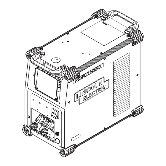
- Page 40 Index of Sub Assemblies - 12483 PART NUMBER DESCRIPTION P-885-A Index of Sub Assemblies P-885-C Case Front Assembly P-885-D Base & Power Conversion Assembly P-885-E Case Back Assembly P-885-F Roof Assembly Power Wave R500 - 12483...
- Page 41 Index of Sub Assemblies - 12483 P-885-A.jpg Power Wave R500 - 12483...
- Page 42 SELF TAPPING SCREW 9SG8555 Nameplate 9ST10397-23 PLUG BUTTON 9ST10397-3 PLUG BUTTON 9SS18657 SQUARE FLANGE FEMALE RECEPTACLE 9SS9262-80 PLAIN WASHER 9SE106A-15 LOCKWASHER 9SCF000021 1/2-13X1.00HHCS 9SS9262-80 PLAIN WASHER 9SE106A-15 LOCKWASHER 9SCF000030 1/2-13X1.25HHCS 9SS9225-99 SELF TAPPING SCREW 9SL15069 COVER PLATE Power Wave R500 - 12483...
- Page 43 Case Front Assembly PART NUMBER DESCRIPTION 9SS9225-99 SELF TAPPING SCREW 9SG6529 UI TRIM 9SG6601-1 DECAL - UI COVER PLATE Power Wave R500 - 12483...
- Page 44 Case Front Assembly P-885-C.jpg Power Wave R500 - 12483...
- Page 45 REAR DIVIDER PANEL ASSEMBLY 9SG5053 REAR DIVIDER PANEL 9SG7245 CHOPPER - HEATSINK ASBLY 9SS9262-27 PLAIN WASHER 9ST9187-13 #10-24HLN-1817/1-NYLON INSERT 9SM22489-2 INPUT PC BD ASBLY 9SS9262-27 PLAIN WASHER 9ST9187-13 #10-24HLN-1817/1-NYLON INSERT 9ST9187-13 #10-24HLN-1817/1-NYLON INSERT 9SS9225-99 SELF TAPPING SCREW Power Wave R500 - 12483...
- Page 46 Nameplate 9SS28841 GROUND LUG 9SCF000013 1/4-20X.625HHCS 9ST9695-17 LOCKWASHER 9SG7150 POWER CONVERSION ASBLY 9SS9225-99 SELF TAPPING SCREW 9SS9262-27 PLAIN WASHER 9ST9187-13 #10-24HLN-1817/1-NYLON INSERT 9SM22895 AIR BAFFLE 9ST9187-13 #10-24HLN-1817/1-NYLON INSERT 9SM22908 INPUT BOARD COVER 9SS18491-3 M.O.V. ASBLY Power Wave R500 - 12483...
- Page 47 Base & Power Conversion Assembly P-885-D.jpg Power Wave R500 - 12483...
- Page 48 BOX RECEPTACLE SOLID SHELL 9SS25438-2 CONNECTOR ADAPTER PLATE 9SS8025-96 SELF TAPPING SCREW 9ST9187-13 #10-24HLN-1817/1-NYLON INSERT 9SS17062-9 CABLE CONNECTOR CAP 9SL15108-2 BRICKWORK PANEL 9SS9225-99 SELF TAPPING SCREW 9SM22519 CONNECTOR & LEAD ASBLY 9SS12021-73 BOX RECEPTACLE SOLID SHELL Power Wave R500 - 12483...
- Page 49 GROUND REFERENCE 9SCF000010 #10-24HN 9SE106A-1 LOCKWASHER 9SS18858-17 SUPPRESSOR ASSEMBLY 9SL13418-2 WIRING HARNESS 9SS28068-2 ADAPTER PLATE 9SS24843-12 HEADER PLUG 9ST9187-13 #10-24HLN-1817/1-NYLON INSERT 9SS28547 SOLENOID MTG PLATE 9SS9225-99 SELF TAPPING SCREW 9ST10397-4 PLUG BUTTON 9SS9225-99 SELF TAPPING SCREW Power Wave R500 - 12483...
- Page 50 Case Back Assembly P-885-E.jpg Power Wave R500 - 12483...
- Page 51 9SM22907 ACCESS DOOR 9SS9225-99 SELF TAPPING SCREW 9SS20900 WARNING DECAL 9SM22782 RIGHT CASE SIDE 9SL15258 RIGHT CASE SIDE 9SS27368-4 DECAL LE LOGO 9SS27468 POWERWAVE LOGO 9SG7188-5 Wiring Diagram 9SS28039-2 DECAL GREEN INITIATIVE 9SS9262-182 PLAIN WASHER Power Wave R500 - 12483...
- Page 52 VOLTAGE SENSE BRACKET 9SM19540-3 VOLTAGE SENSE SELECT PC BD ASBLY 9ST13637-6 DIODE-BRIDGE35A400VF-W1-PH 9SS9262-27 PLAIN WASHER 9SE106A-1 LOCKWASHER 9SCF000010 #10-24HN 9SS9225-99 SELF TAPPING SCREW 9SM19969-13 ETHERNET PATCH CABLE ASBLY 9SG6525-3 HANDLE 9SCF000410 1/4-20x.75HHCS-FULL-GR2-4554 9SE106A-27 LOCK WASHER Power Wave R500 - 12483...
- Page 53 Roof Assembly P-885-F.jpg Power Wave R500 - 12483...
- Page 54 Do not touch electrically live parts or Keep flammable materials away. Wear eye, ear and body protection. WARNING electrode with skin or wet clothing. Insulate yourself from work and ground. Spanish No toque las partes o los electrodos Mantenga el material combustible Protéjase los ojos, los oídos y el AVISO DE bajo carga con la piel o ropa moja-...
- Page 55 Keep your head out of fumes. Turn power off before servicing. Do not operate with panel open or WARNING Use ventilation or exhaust to guards off. remove fumes from breathing zone. Spanish Los humos fuera de la zona de res- Desconectar el cable de ali- No operar con panel abierto o AVISO DE...
- Page 56 Lincoln Electric for advice or information about their use of our products. We respond to our customers based on the best information in our possession at that time. Lincoln Electric is not in a position to warrant or guarantee such advice, and assumes no liability, with respect to such information or advice.
Need help?
Do you have a question about the POWER WAVE R500 and is the answer not in the manual?
Questions and answers