
Related Manuals for Pertech 5351


Summary of Contents for Pertech 5351
-
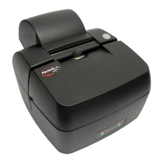
Page 1: Series Printer
5351 Series Printer Technical Support Documentation Pertech Resources Inc. 2007 2202xxx Rev.00... -
Page 2: Web Site
Disclaimer Information in this document is subject to change without notice. Consult your Pertech® sales representative for information that is applicable and current. Pertech reserves the right to improve products as new technology, components, software and firmware become available. No part of this document may be reproduced or transmitted in any form or by any means, electronic or mechanical, for any purpose with out the express written permission of Pertech. - Page 3 A shielded (360 degree) interface cable must be used with this product. The shield must be connected to the frame or earth ground reference at each end of the cable. Use of a cable other than the described here will require that you test this cable with the Pertech printer and your system for FCC and CE mark certification.
-
Page 4: Table Of Contents
Program Error/ Firmware Error...................34 Home Sensor Error.....................34 No Power Light ......................34 Paper Light On ......................34 Red Power Light On ....................34 Green Power Light On....................35 No Print & Print Quality Issues ..................35 Validation issues......................35 Other..........................35 5300 Printer Problem Survey..................36 Pertech Technical Support ......................37... -
Page 5: Preface
Preface This manual has been written to help you Install and Operate your Pertech® 5300 Series Printer. Feel free to contact us if you need further assistance after reading this manual. Please see the Troubleshooting Printer Problems section of this manual and determine the complete part number of your printer prior to calling. Pertech provides technical support Monday through Friday from 8:00 AM to 5:00 PM MST at 307-856-4821. -
Page 6: Ordering Paper And Supplies
The following section lists the paper and supplies available for order. In addition to paper and ribbons, parts, service and repair may be obtained by calling 1-800-800-6614. Paper: Call: 1-800-800-6614 Paper Part Number Ink Jet 5351 One Ply....................... 103292057 Impact 5371 One Ply....................... 103292062 Two Ply ....................... 103292061 Cartridge’s:... -
Page 7: Led Mode Indicators
LED Mode Indicators The 5300 series printers are equipped with two color led indicators that identify Paper, Error, Ink Low, Form In, and Power On conditions. Status Left LED Right LED Power On Green Insert form Blink Green Current Status Form is in Green Current Status... -
Page 8: Led Error Fault Mode Diagnostics
LED Error Fault Mode Diagnostics The printer will enter a Fault Mode and will not operate when certain failure conditions are encountered. Confirmation of this condition can be accomplished by the host on the DTR (pin 8) or status with an RS-232 interface. A Printer in fault mode will not feed paper when the paper advance button on the top cover is depressed nor will it execute commands other than immediate commands that are executed even when the printer is in a fault condi- tion. -
Page 9: Validation And Document Guides
Validation and Document Guides Validation Print Fields Dot column #1 Dot Column #400 The 5300 series printer has 2.5 inch wide print field. The validation print field height is adjustable from .17 to 1.75 3 Inches Print Zone 1 Inch 2 Inches for 6”... -
Page 10: Document Guide Installation
Document Guide Installation The Document Guide is a clip in durable plastic part that attaches to the printers Validation Roller to provide a right side guide for an inserted form. NOTE: Before installing the Document Guide make sure the area where the guide is to be installed is free of any dust debris or contamination that could inhibit the movement of the Validation Roller. -
Page 11: Document Drop Stop Installation
Document Drop Stop Installation A pair of tweezers, mylar Document Drop Stop, PN# 108693 (DDS), and an Alcohol Prep are the Items necessary to do this installation. Pre-Install: 1. Open front cover. Print head should move to right side, compensator validation clamp position should be open. - Page 12 Document Drop Stop Placement Bend in Mylar...
- Page 13 Clean the installation area with an alco- hol swab and peel the backing off the (DDS). With a pair of tweezers attach the DDS to the paper deflector assembly. (See PICTURES BELOW & PREVIOUS PAGE FOR PROPER ALIGNMENT ) Reassemble & Test printer. If installed into Impact 537X model, with compensator closed, push print head left to right to be sure print head shield clears...
-
Page 14: Connections
Connections Connecting the Cables Caution: Be sure the power switch is turned off before connecting cables. The host computer should be turned off before connecting any cables. Power Serial Cash Drawer RS232 Serial Interface 1. Make sure the host computer and printer are turned off. 2. - Page 15 The USB cable may be attached or detached when the system is on. When Using the USB interface the Win- dows® Operating System will automatically install the USB port driver. Pertech has available printer drivers at www.pertechresources.com. Warning: When Hot Swapping USB cable make sure that cable is installed into the correct connectors or damage to the printer could result.
-
Page 16: Paper Loading
Paper Loading Paper and other printer consumables may be purchased from Pertech by calling 1-800-800-6614. Roll paper must be 3.0 inches wide +/- .03 inches (.762mm) with a maximum diameter of 3.5 inches (88.9mm). Ink Jet 535X receipt printers can accommodate 1 paper ply. Impact 537X receipt printers can accommodate 1 or two paper plys. -
Page 17: Drive Belt -Column Alignment Adjustment
Tighten the Adjustment Screw and check the column alignment via a printer resident test. Column alignment can also be adjusted by using a configuration utility that Pertech Provides on our web site. This method does not adjust the belt tension. -
Page 18: Configuration
Configuration Configuration Report & Setup Mode After the printer is set up, you can run two print diagnostic reports / tests and enter the configuration menu. Below is an example of the configuration report. Serial Number: ******** Main Firmware 1 Press and hold the Paper Feed Button and then Revision: * ** *** CRC:... -
Page 19: Configuration Example
Configuration Example: ================================= Configure the RS232 Serial parameters for the printer using the Press paper feed to change configuration configuration menu. SET-UP INSTRUCTIONS PRESSING THE PAPER FEED BUTTON WHILE THE Current Param- Change to: GREEN LIGHT IS FLASHING WILL REJECT THE LAST PRINTED PARAMETER. -
Page 20: Printer Configuration Options
Printer Configuration Options Options for ACL Compatibility Mode Serial Number: ******** Main Firmware Revision: * ** *** CRC: **** Boot Firmware Revision: * ** *** CRC: ���� �������� **** ���� � ������� Printer Control Language ���� � �������� PCL: ACL Language ����... -
Page 21: Inspection & Testing
Inspection & Testing Test results should be recorded on a data sheet for each printer and should accompany the printer. A sample data sheet is include at the end of this Section. Visual Inspection: Operational Testing: The purpose of the visual inspection is to The purpose of the operational test is to test the printer for in field determine if the printer is within its product life or functionality. -
Page 22: Parts Identification
5. Parts Identification Item Number Qty Item Description Item Number Qty Item Description 108628001A 1.00 101 MECH ASSY-I.J VAL. & RECEIPT 108635001A 1.00 141 CASE TOP REAR ASSY, BLACK 100261046 0.00 102 ADHESIVE (TORQUE SEAL, PURPLE) 108535010C 1.00 142 CASE-BOTTOM, BLACK 100173240 3.00 104 SCREW-WASHER... -
Page 23: Parts Inspection
6. Parts Inspection a) Pressure Roller, Validation (seals) Make sure purple loctite seal is not broken. b) Compensator assembly c) Printhead Assembly Ink Cartridge Holder Ribbon Head Connector... - Page 24 d) Case Parts The case is a durable plastic that should be inspected for missing feet, cover latches that are broken or have become disengage from their seats. The later is usually a indication that the printer has been dropped. Addtiionally the paper roll cover should move freely and fit flush into the rear cover mold.
- Page 25 f) Sensors Paper Out Sensor Lid Open Switch Located in the paper path below visibility. With Lid Open switch inactivat- Use Operational Test to verify working. ed (cover open) Led on front of printer will Flash. Carriage Home Sensor Form In Sensor Keep free from dust and debris.
- Page 26 Paper Mandrel Make sure the paper mandrel spins freely with no paper installed. Make sure the mandrel in seated on both sides in the mounting slots. Paper Mandrel Seats k) Interface Cable Check the cable to make sure no Pins are bent or the cord is not cracked or damaged.
-
Page 27: Operational Test Procedure
Operational Test Procedure 1. Power supply Check the power supply connectors and cable for any damage. Connect the power supply to the printer and then to a power source. Turn the printer on . The green Power LED on the printer should light. �����... -
Page 28: Validation
Validation can be tested by using the your application or by using the configuration test described in the Printer Resident Tests section. Additionally, a 5300 Pertech demo program can be supplied for testing purposes. When the application uses the correct control codes to initiate validation the printer will open the compensator for a validation form to be inserted. -
Page 29: Printer Resident Tests
Printer Resident Tests There are four routines resident in the printer. Each is initiated during power up with other specific action taken. Confirm normal initialization prior to executing a self test by turning power on with the lid closed. Listen for the mechanism to initialize, then rase the cover and ensure the printhead centers. -
Page 30: Printer Inspection And Testing Data Sheet
Printer Inspection and Testing Data Sheet Testing Individual Test Date Test Locatio Accepted Failed Notes Model Number Revision Number Serial Number Environmental Conditions Visual Inspection Pressure Roller, validation Seals Compensator assembly Printhead Assembly Ribbon Feed Assembly Case Parts Paper Feed Button Sensors Paper Feed Assembly Document Stop... -
Page 31: Trouble Shooting
Trouble Shooting Trouble shooting information should be recorded on the accompanying 5300 Printer Problem Survey lo- cated on at the end of this section. Trouble Shooting procedure should begin with the identification of the customer, printer and customer issue. Follow the chart below for trouble shooting information. Many printer issues can be easily solved without having to have the printer serviced by a technician. -
Page 32: Trouble Shooting General Issues
After the printer is configured, set the printer driver port back to the correct COM port D. Utility does not communicate with USB connected printer. If using Windows 98 SR2, you may need to contact Pertech Resources for Microsoft’s USBPRINT.SYS driver. Win- dows ME, 2000 and XP already include this driver. - Page 33 H. Paper Jam Solution: Open cover and remove supply roll. Grasp paper and gently pull paper out of the printer if paper does not move freely gently pull the paper the opposite direction momentarily until it frees. Once paper is removed be sure no paper bits still exist in the printer.
-
Page 34: Fault Mode Diagnostics
Symptom Action No Power Light Check the power supply to make sure it is plugged in and the printers power switch is turned on. & printer will not function Check the connector on the back of the printer and the cord connection to the power brick. -
Page 35: Green Power Light On
Symptom Action Green Power Light On Paper wont feed when pressing paper actua- Lower actuator arm is not engaging the feed switch or feed switch tor Arm. is not working. Check arm by switch to see if it is obstructed, If not printer needs to be checked out by a trained technician. -
Page 36: 5300 Printer Problem Survey
5300 Printer Problem Survey Date: Company Name Contact Model Number Serial number Customer Indicated Problem. (Symptom) What has changed with the system before the failure. What was happening before the issue occurred. What has been done to resolve the issue. What is LED Status: (See Trouble Shooting Section for help in Issue identification) Power Indicator on front of printer is: GREEN... -
Page 37: Pertech Technical Support
Pertech Technical Support Pertech™ provides Technical Support for this product by calling 307-856-4821 between the hours of 8AM to 5PM Monday through Friday MST, or by submitting a Support Inquiry at the Pertech web site. www.pertechresources.com under the service/support section.
Need help?
Do you have a question about the 5351 and is the answer not in the manual?
Questions and answers