Table of Contents
Advertisement
Quick Links
This manual covers the following models:
This manual covers TopTech models:
• T955W Master Thermostat
TT-S-955W and T955W
• Base Module
Thermostat Applications Guide
Description
Gas or Oil Heat
Electric Furnace
Heat Pump (No Aux. or Emergency Heat)
Heat Pump (with Aux. or Emergency Heat)
Multi-stage Systems
Heat Only Systems
Cool Only Systems
Dual Fuel Systems
Millivolt
Table of Contents
Una versión española de este
manual puede ser descargada
en www.pro1iaq.com
® U.S. Registered Trademark. Patents pending.
Copyright © 2010 PRO1 IAQ, Inc. All rights reserved.
INSTALLATION MANUAL
Power Type
Battery Power
Hardwire (Common Wire)
Yes
Yes
Hardwire (Common Wire) with Battery Backup
Yes
Yes
Yes
Yes
Yes
*
If using remote sensors the thermostat
Yes
must be hardwired.
No
Page
A trained, experienced technician
must install this product.
2
3-5
Carefully read these instructions. You
6-7
could damage this product or cause a
8
hazardous condition if you fail to follow
9
these instructions.
10-13
14
15-18
19
Need Help?
For assistance with this product please
visit http://www.pro1iaq.com or call Pro1
Customer Care toll-free at 888-Pro1iaq
(776-1427) during normal business hours
(Mon-Fri 9 AM - 6 PM Eastern)
*
Rev. 0950
1
Advertisement
Table of Contents

Subscribe to Our Youtube Channel
Related Manuals for Toptech truecomfort iii


Summary of Contents for Toptech truecomfort iii
-
Page 1: Table Of Contents
INSTALLATION MANUAL This manual covers the following models: This manual covers TopTech models: • T955W Master Thermostat TT-S-955W and T955W • Base Module Power Type Thermostat Applications Guide Battery Power Description Hardwire (Common Wire) Gas or Oil Heat Electric Furnace Hardwire (Common Wire) with Battery Backup Heat Pump (No Aux. -
Page 2: Thermostat Quick Reference
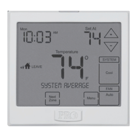
Getting to know your thermostat Important: The low battery indicator is displayed when the AA battery power is low. If the user fails to replace the battery within 21 days, the thermostat display will only show the low battery indicator as a final warning before the thermostat becomes inoperable. -
Page 3: Installation Tips
INSTALLATION TIPS Wall locations The thermostat should be installed approximately 4 to 5 feet above the floor. Select an area with average temperature and good air circulation. Do not install thermostat in locations: • Close to hot or cold air ducts •... - Page 4 INSTALLATION TIPS Base Module - Basement Installation ATTIC INSTALLATION ON THE NEXT PAGE Wireless Range Range between the T955W and the base module is up to 100 feet with no obstructions and up to 50 feet in standard residential metal, brick, and concrete construction. To extend the range try placing the base unit higher if in a basement or further away from large metal objects.
- Page 5 INSTALLATION TIPS Base Module - Attic Installation When performing an attic installation, instead of placing the base module in the attic, locate the closet nearest to the air conditioning unit. Then mount the base module high on the wall inside the closet or on the ceiling of the closet. This location will insure the base module is below the 150ºF maximum ambient temperature specification.
-
Page 6: Subbase Installation
MASTER THERMOSTAT SUBBASE INSTALLATION Caution: Mercury Notice: Electrical Hazard All of Pro1’s products are mercury free. However, if the Failure to disconnect the product you are replacing power before beginning to contains mercury, dispose of it install this product can cause properly. -
Page 7: Subbase Installation
BASE MODULE SUBBASE INSTALLATION Wiring Note: Note: Wire the base module’s subbase To connect the base module to the same way you would wire a master thermostat, refer to the hardwired thermostat subbase. directions on page 9 of this manual. For vertical mount put one screw top and one screw bottom. -
Page 8: Wiring
WIRING Wiring Warning: All components of the control If you are replacing a thermostat, make system and the thermostat note of the terminal connections on the installation must conform to thermostat that is being replaced. In some Class II circuits per the NEC Code. cases the wiring connections will not be color coded. -
Page 9: Establishing Communication
ESTABLISHING COMMUNICATION Establishing Communication between T955W Master Thermostat and the Base Module Easy, Two Step Communication Link To set up the initial link between the Master Thermostat Step 1. and the base module please follow the steps below: LED Relay Indicators Blue LED Press and hold the base module button for 3 seconds. -
Page 10: Technician Setup Menu
TECHNICIAN SETUP MENU Technician Setup Menu Configure the installer options as This thermostat has a technician setup menu desired using the table below. for easy installer configuration. To set up the thermostat for your particular application: Use the keys to Press MENU button change settings and the NEXT STEP or PREV STEP key to move from one... -
Page 11: Balance Point
TECHNICIAN SETUP MENU Tech Setup Steps (Continued from the previous page) Heating Cooling ºF or ºC 12 or 24 Morning Program Display Temperature Temperature Hour Clock Recovery Options Light Setpoint Limit Setpoint Limit This feature This feature You can select This feature turns your You can configure this The display light can... - Page 12 TECHNICIAN SETUP MENU Tech Setup Steps (Continued from the previous page) Contractor Beep Heat Pump System Gas Auxiliary Cooling Fan Outdoor Call Number Switch Operation for Heat Pump Delay Sensor This option will turn The cooling fan delay Enables the use of an Allows you to put When any key is When turned on...
- Page 13 TECHNICIAN SETUP MENU Tech Setup Steps (Continued from the previous page) Tech Setup Steps (Continued from the previous page) Requires R250W Remote Stages Balance Balance Finding Local Temp Freeze Energy Star ® Sensor of Heat Point Run Time Sensor Sensor Protection Logo Enables the use of up...
-
Page 14: Mounting & Battery Installation
MOUNT THERMOSTAT & BATTERY INSTALLATION Mount Thermostat and Base Module Note: Align the 4 tabs on the subbase with corresponding The base module can be wired slots on the back of the thermostat or base module. from the back or the bottom. Then push gently until the thermostat or base module snaps in place. -
Page 15: Programming The Thermostat
PROGRAMMING THE THERMOSTAT Set Time Follow the steps below to set the day of the week and current time: Press MENU Press SET TIME Day of the week will be flashing. Use the key to select the current day of the week. Press NEXT STEP The current hour is flashing. - Page 16 PROGRAMMING THE THERMOSTAT You can use the table below to plan your customized program schedule if using 5+1+1.
- Page 17 PROGRAMMING THE THERMOSTAT Set 5+1+1 Program Schedule To customize your 5+1+1 program schedule, follow these steps Weekday: Select HEAT or COOL using the SYSTEM key. Note: You have to program heat and cool each separately. Press MENU Press SET SCHED. Note: Monday-Friday is displayed and the WAKE icon is shown. You are now programming the WAKE time period for the weekday setting.
-
Page 18: Programming The Thermostat
PROGRAMMING THE THERMOSTAT Set 7 Day Program Schedule To customize your 7 day program schedule, follow these steps: Monday Select HEAT or COOL using the system key. You have to program heat and cool each separately. Press MENU Press SET SCHED Note: Monday is displayed and the WAKE icon is shown. -
Page 19: Specifications & Contact Info
SPECIFICATIONS & CONTACT INFORMATION Specifications T955W Thermostat The display range of temperature 41ºF to 95ºF (5ºC to 35ºC) The control range of temperature 44ºF to 90ºF (7ºC to 32ºC) Load rating 1 amp per terminal, 1.5 amp maximum all terminals combined ±...
Need help?
Do you have a question about the truecomfort iii and is the answer not in the manual?
Questions and answers
Can we buy replacement?