Hitachi NV 83A2 Technical Data And Service Manual
Hide thumbs
Also See for NV 83A2:
- Instruction and safety manual (60 pages) ,
- Instruction manual (38 pages) ,
- Instruction and safety manual (72 pages)

Related Manuals for Hitachi NV 83A2


Summary of Contents for Hitachi NV 83A2
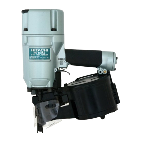
- Page 1 MODEL NV 83A2 POWER TOOLS TECHNICAL DATA COIL NAILER NV 83A2 SERVICE MANUAL LIST No. E007 Oct. 2002 SPECIFICATIONS AND PARTS ARE SUBJECT TO CHANGE FOR IMPROVEMENT...
- Page 2 REMARK: Throughout this TECHNICAL DATA AND SERVICE MANUAL, a symbol(s) is(are) used in the place of company name(s) and model name(s) of our competitor(s). The symbol(s) utilized here is(are) as follows: Competitors Symbols Utilized Company Name Model Name SCN65 SENCO PASLODE P350C N80CB...
-
Page 3: Table Of Contents
10-4. Disassembly and Reassembly of the Magazine Section ............. 29 10-5. Disassembly and Reassembly of the Driving Section ............32 10-6. Grip Rubber ......................... 36 11. INSPECTION AND CONFIRMATION AFTER REASSEMBLY ..........37 12. STANDARD REPAIR TIME (UNIT) SCHEDULES ............... 38 Assembly Diagram for NV 83A2... -
Page 4: Product Name
Model NV 83A2 is equipped with a tool-less nailing depth adjuster, pop-out magazine, non-slip rubber, etc. to meet the market demands. Applicable nails are the same as those of the Model NV 83A. The Model NV 83A2 weighs only 3.7 kg (same as the Model NV 83A). - Page 5 (2) Adjuster While the Model NV 83A requires a wrench to adjust the nailing depth, the Model NV 83A2 requires no tool for adjustment. Amount of adjustment is about 4.5 mm (0.177").
-
Page 6: Specifications
5. SPECIFICATIONS 5-1. Specifications NV 83A2 Model Driving system Reciprocating piston type 5 --- 8.5 kgf/cm (70 -- - 120 psi, 4.9 --- 8.3 bar) (Gauge pressure) Operating pressure Driving speed Min. 3 pcs./sec. Weight 3.7 kg (8.2 lbs.) Dimensions... -
Page 7: Nail Selection
5-2. Nail Selection The Model NV 83A2 utilizes common round-head nails collated by wire or sheet into coils from 200 to 300 pieces. Applicable nail dimensions are shown below. However, it is recommended to use genuine HITACHI nails to ensure satisfactory driving quality. -
Page 8: Nail Driving Force
For example, when driving a nail of 3.3 mm dia. by 83 mm length (0.131" x 3-1/4") into nine sheets of 12 mm plywood (108 mm thick) with the Model NV 83A2, a pressure of about 7.0 bar (7.1 kgf/cm , 102 psi) allows the nailer to drive the nail flush with the wood surface. -
Page 9: Optional Accessories
Sequential trip mechanism kit (Single shot) (Code No. 876762) A sequential trip mechanism kit is provided as an optional accessory for the Model NV 83A2. By using this optional accessory, a nail is driven by pressing the pushing lever first against a workpiece and then pulling the trigger (single-shot operation), and no nail is driven when pulling the trigger first and then pressing the pushing lever against a workpiece. -
Page 10: Comparisons With Similar Products
--- 7 ---... -
Page 11: Precautions In Sales Promotion
7. PRECAUTIONS IN SALES PROMOTION In the interest of promoting the safest and most efficient use of the Model NV 83A2 Nailer by all of our customers, it is very important that at the time of sale the salesperson carefully ensures that the buyer seriously recognizes the importance of the contents of the Instruction Manual, and fully understands the meaning of the precautions listed on the Warning Label attached to each tool. -
Page 12: Related Laws And Regulations
(2) If dust in the compressed air settles on the sliding portion, the Model NV 83A2 will not operate properly. Lubrication is effective to remove dust and also to prolong the service life of the Model NV 83A2 keeping good performance. -
Page 13: Mechanism And Operation Principle
8. MECHANISM AND OPERATION PRINCIPLE 8-1. Mechanism As illustrated in Fig. 3, the Model NV 83A2 can be generally divided into four sections: output section, control valve section, driving section and magazine section. Although the output section and the valve section are basically common to those of the Model NV 83A, most of the parts of the driving section and the magazine section have been newly designed. -
Page 14: Interchangeability Of Parts
The driving section and the magazine section are not interchangeable between the Model NV 83A2 and the NV 83A because these sections of the Model NV 83A2 have been newly designed. The output section and the control valve section are interchangeable except the following parts. - Page 15 Part NV 83A2 NV 83A Pushing Lever [54] Bent. Welded. Cover [105] --- 12 ---...
-
Page 16: Operation Principle
8-3. Operation Principle (1) When the compressed air source (air hose) is connected to the nailer: Air pressure is applied to the lower surfaces of the flanges located at the center portion of the cylinder, forcing the cylinder upward. The compressed air is thereby blocked from the upper end of the cylinder, and no pressure is applied to the Piston. - Page 17 (2) When the trigger and pushing lever are operated: Although air pressure is applied to both the upper and lower Compressed air is applied surfaces of the cylinder, the to the upper side of the cylinder is forced downward due exhaust valve, forcing it to the larger effective area of the Cylinder ring...
- Page 18 (3) If the trigger and pushing lever are kept pressed: Air pressure is applied in the shaded areas in the illustration, and each component is held in the position illustrated. If the operator's grip is loosened, air will leak. As there is no O-ring installed here, a very small amount of air will leak from the slight clearance between the components.
- Page 19 (4) When the trigger and/or pushing lever are released: The pressure on the upper surface of the exhaust valve is released, and the exhaust valve is pushed upward by the air pressure within the cylinder. This opens the exhaust vent, and the air pressure in the cylinder and the left-side surface of the feed piston are discharged from the nailer.
-
Page 20: Troubleshooting Guide
9. TROUBLESHOOTING GUIDE 9-1. Troubleshooting and Correction Possible cause Problem Inspection method Remedy : Most-common cause) 1) Nails cannot <Nails> be driven. Magazine is not loaded with Check that the magazine is Use specified nails. specified genuine nails. correctly loaded with Remove the abnormal nails Magazine is loaded with specified nails. - Page 21 Possible cause Problem Inspection method Remedy : Most-common cause) Tighten screws and replace Air leaks from Gasket (A). 1) Nails cannot gaskets. be driven. (continued) Replace the O-rings. O-rings are worn or deformed. Apply grease or lubricate. O-rings need lubrication. <Nail guide section>...
- Page 22 Possible cause Problem Inspection method Remedy : Most-common cause) 1) Nails cannot Cylinder inside surface is Remove dust and then Check that nails can be be driven. abnormal (packed with lubricate. driven at 5 kgf/cm (4.9 bar, (continued) dust, or worn). Replace the part.
- Page 23 Possible cause Problem Inspection method Remedy : Most-common cause) Piston O-ring is abnormal Replace the abnormal part. Disassemble the output 3) Nails cannot (worn or damaged). section and check inside be driven into and outside surfaces of the the workpiece Cylinder inside surface is O-ring and the cylinder for completely:...
- Page 24 Possible cause Problem Inspection method Remedy : Most-common cause) Use specified nails. 4) Nails jam. Check if the specified nails <Nails> Remove the abnormal nails are used. Unspecified nails are used. and load the nailer with Check the nails as follows. Abnormal nails are mixed.
-
Page 25: Possible Causes And Corrections Of Air Leakage
9-2. Possible Causes and Corrections of Air Leakage Air leakage repair location A --- A --- 22 ---... - Page 26 Inspection priorities: In the table below, possible causes of air leakage and their repair procedures are marked in accordance with the likelihood of possible failure. (1) First priority items are marked with an asterisk ( ). (2) Second priority items (seal portions) are marked with a double circle ( (3) Remaining items are marked with a single circle ( ).
- Page 27 Cause Air leak part When trigger valve ON/ When trigger valve/ When trigger valve/safety valve are OFF safety valve are ON safety valve OFF Defective O-ring [69] of Feed Piston [70] (worn, Feed piston deformed or cut) Defective Feed Piston [70] sliding portion (damaged, deformed or broken)
-
Page 28: Disassembly And Reassembly
Apply grease (Nippeco SEP-3A, Code No. 930035) to the O-rings and O-rings' sliding portions. When installing the O-rings, be careful not to damage the O-rings and prevent dirt entry. Oil required: Hitachi pneumatic tool lubricant 1 oz (30 cc) oil feeder (Code No. 877153) 4 oz (120 cc) oil feeder (Code No. -
Page 29: Disassembly And Reassembly Of The Output Section
10-2. Disassembly and Reassembly of the Output Section (1) Piston (H) [12], Cylinder [17] and related parts Tool required: Hexagon bar wrench (5 mm) (a) Disassembly (See Figs. 10, 11 and 12.) Remove the four Hex. Socket Hd. Bolts (W/Sp. Washer) M6 x 25 [3], and take off the Exhaust Cover [4]. The Piston (H) [12] can then be taken out. - Page 30 Exhaust Piece [7] attention should be given to the following items. Gasket (C) [8] Gasket (C) [8] and Gasket (F) [6] should be replaced with new genuine Hitachi parts. Exhaust Valve [9] Apply the designated grease to the outer Head Cap and...
-
Page 31: Disassembly And Reassembly Of The Control Valve Section
10-3. Disassembly and Reassembly of the Control Valve Section Tool required: Roll pin puller (3 mm (0.118") dia.) Minus-hd. screwdriver (a) Disassembly (See Fig. 12.) Remove the Magazine [81] as described in section 10-4. Remove the Pushing Lever [54] as described in section 10-5. With the roll pin puller (3 mm (0.118") dia.), take out the Roll Pin D3 x 30 [63], and remove the Trigger [62], Trigger Plunger [68] and Safety Plunger (B) [61]. -
Page 32: Disassembly And Reassembly Of The Magazine Section
10-4. Disassembly and Reassembly of the Magazine Section Tools required: Phillips screwdriver Roll pin pullers (4 mm dia., 2.5 mm dia.) Hex. bar wrench (4 mm) Wrench M5 (1) Disassembly and reassembly of the magazine section (a) Disassembly (See Fig. 15.) Loosen the Hex. - Page 33 (b) Reassembly Disassembly procedures should be followed in the reverse order. Note the following points. Bend the tip of the Cover [105] and engage it with the convex portion of Magazine [81]. Hold it with Guard [80] positioning the Cover [105] outside Guard [80]. Nylon Nut M5 [78] Body (B) [27] Magazine [81]...
- Page 34 (2) Disassembly and reassembly of nail holder, holder shaft, etc. (a) Disassembly Pull out the two Pins [82] with a roll pin puller (4 mm dia.). Then Magazine [81] and Magazine Cover [84] can be removed. Remove Holder Cap [85] and Roll Pin D2.5 x 18 [88] with a roll pin puller (2.5 mm dia.). Then Nail Holder [87], Holder Shaft [89] and Spring [90] can be removed.
-
Page 35: Disassembly And Reassembly Of The Driving Section
10-5. Disassembly and Reassembly of the Driving Section Safety Plunger (B) [61] Body (B) [27] Seal Lock Hex. Socket Hd. Bolt M5 x 10 [76] Cylinder O-ring [28] Piston Bumper (B) [29] Magazine Bushing [77] Feed Piston Cover [75] Gasket (A) [30] Feeder Shaft Ring [32] Feed Piston Cover (A) [74] Bumper [73]... - Page 36 (1) Tail Cover [31], Pushing Lever [54] and the related parts (See Fig. 17.) Tools required: Hexagon bar wrench (6 mm) Roll pin puller (3 mm (0.118") dia.) Screwdriver (a) Disassembly Pull out the Roll Pin D3 x 45 [53]. Then Valve Guard [52] can be removed. Remove the four Nylock Hex.
- Page 37 Feeder Set [35]. Prior to reassembly, apply grease (Hitachi Motor Grease No. 29, Code No. 930035, is recommended) to O-ring (P-9) [69], O-ring (P-22) [71], O-ring sliding portions of the Feed Piston [70] and Tail Cover [31].
- Page 38 (4) Disassembly and reassembly of Nail Guide [95], Sub Nail Stopper [92], Feeder Set [35] and other parts (See Fig. 19.) Tools required: Flat-blade screwdriver Hex. bar wrench 3 mm Roll pin puller (3 mm (0.118") dia.) (a) Disassembly Remove the Shaft Ring [91] from the Nail Guide Shaft [101] with a flat-blade screwdriver and remove the Nail Guide Shaft [101].
-
Page 39: Grip Rubber
10.6 Grip Rubber The Model NV 83A2 is equipped with the grip-rubber handle that is common to the Model NR 83AA2. However, the grip rubber is not supplied as a spare part because it is difficult to detach/attach the grip rubber. If replacement of the grip rubber is required, replace the Body (B) [27] or attach the grip tape. -
Page 40: Inspection And Confirmation After Reassembly
11. INSPECTION AND CONFIRMATION AFTER REASSEMBLY Check that Safety Plunger (B) [61] and Trigger Plunger [68] move smoothly. Check that there is no air leakage from each part. While driving nails with an air pressure of 4.5 kgf/cm (63 psi), check that there is no idle driving and bending of nails. -
Page 41: Standard Repair Time (Unit) Schedules
12. STANDARD REPAIR TIME (UNIT) SCHEDULES Variable 60 min. MODEL Fixed Work Flow NV 83A2 Cylinder Plate Cylinder Exhaust Cover Cylinder Ring Exhaust Piece Cylinder Spring Exhaust Valve Cylinder Guide Head Cap Piston Bumper Gasket Set Gasket x 3 Cylinder... - Page 42 LIST NO. E007 PNEUMATIC TOOL PARTS LIST COIL NAILER 2002 • • Model NV 83A2 (E1) 505 506...
- Page 43 PARTS NV 83A2 ITEM CODE NO. DESCRIPTION REMARKS USED 883-509 HEX. SOCKET HD. BOLT (W/FLANGE) M6X45 877-330 TOP COVER 883-507 HEX. SOCKET HD. BOLT (W/SP.WASHER) M6X25 877-324 EXHAUST COVER 877-325 GASKET (B) 877-329 GASKET (F) 877-328 EXHAUST PIECE 877-854 GASKET (C)
- Page 44 PARTS NV 83A2 ITEM CODE NO. DESCRIPTION REMARKS USED 875-650 SAFETY BOLT 884-027 VALVE GUARD 884-025 ROLL PIN D3X45 884-026 PUSHING LEVER 949-555 NUT M5 (10 PCS.) 875-643 PLUNGER SPRING 884-039 PLUNGER (A) 874-820 PLUNGER O-RING 875-638 O-RING (S-12) 878-266...
- Page 45 NV 83A2 PARTS ITEM CODE NO. DESCRIPTION REMARKS USED 949-865 ROLL PIN D3X28 (10 PCS.) 876-681 MAIN STOPPER SPRING 877-469 NAIL GUIDE COVER 884-023 COVER 884-022 PLATE 877-838 SEAL LOCK HEX. SOCKET HD. BOLT M4X 8 884-032 MAGAZINE ASS’Y 1 INCLUD. 81-90...
Need help?
Do you have a question about the NV 83A2 and is the answer not in the manual?
Questions and answers