
Related Manuals for Hitachi NV 65AF3


Summary of Contents for Hitachi NV 65AF3
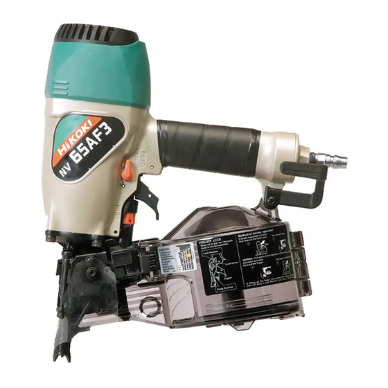
- Page 1 MODEL NV 65AF3 POWER TOOLS TECHNICAL DATA COIL NAILER NV 65AF3 SERVICE MANUAL LIST No. E005 Aug. 2002 SPECIFICATIONS AND PARTS ARE SUBJECT TO CHANGE FOR IMPROVEMENT...
- Page 2 REMARK: Throughout this TECHNICAL DATA AND SERVICE MANUAL, a symbol(s) is(are) used in the place of company name(s) and model name(s) of our competitor(s). The symbol(s) utilized here is(are) as follows: Competitors Symbols Utilized Company Name Model Name CN565S AN611 MAKITA SENCO SCN55S...
-
Page 3: Table Of Contents
10-4. Disassembly and Reassembly of the Magazine Section ............. 29 10-5. Disassembly and Reassembly of the Driving Section ............32 11. INSPECTION AND CONFIRMATION AFTER REASSEMBLY ........... 36 12. STANDARD REPAIR TIME (UNIT) SCHEDULES ............... 37 Assembly Diagram for NV 65AF3... -
Page 4: Product Name
2. MARKETING OBJECTIVE Hitachi coil nailer Model NV 65AF3 has already been introduced on Japan market. This time, it will be put on Oceania market to compete with S, C and Q. The Model NV 65AF3 is the most lightweight and powerful coil nailer in this class and equipped with a muffler to minimize the exhaust sound and blowing dust. -
Page 5: Specifications
5. SPECIFICATIONS 5-1. Specifications NV 65AF3 Model Reciprocating piston type Driving system Operating pressure 5 --- 8.5 kgf/cm (Gauge pressure) {70 --- 120 psi, 4.9 -- - 8.3 bar} Driving speed Min. 3 nails/sec. 1.9 kg (4.2 lbs.) Weight Dimensions... -
Page 6: Nail Selection
5-2. Nail Selection The Model NV 65AF3 utilizes common round-head nails collated by wire or plastic sheet into coils from 200 to 400 nails. Applicable nail dimensions are shown below. CAUTION: Ensure that nails are as specified in Fig. 1. Other nails will cause clogging of nails and subsequent damage to the nailer. - Page 7 Type Unit: mm (inch) 2.1 --- 2.3 32 --- 57 (0.083 --- 0.090) (0.024) (0.472) (0.945) (1-1/4 --- 3-1/4) 118 MAX 22 --- 30 (4.645 MAX) (0.866 --- 1.181) 37.5 45 --- 65 2.5 --- 2.8 (1-3/4 --- 2-1/2) (0.028) (0.748) (1.476) (0.099 --- 0.110)
-
Page 8: Nail Driving Force
For example, when driving a nail of 2.5 mm dia. x 65 mm length (0.099" x 2-1/2") into a workpiece of hemlock with the Model NV 65AF3, a pressure of about 6 bar (6.1 kgf/cm , 87 psi) allows the nailer to drive the nail flush with the wood surface. -
Page 9: Comparisons With Similar Products
6. COMPARISONS WITH SIMILAR PRODUCTS 6-1. Specifications Maker HITACHI Model name NV 65AF3 Operating pressure 8.5 kgf/cm 7 kgf/cm 8.5 kgf/cm 120 psi) 100 psi) 120 psi) (4.9 8.3 bar) (4.9 6.9 bar) (4.4 8.3 bar) Weight 1.9 kg (4.2 lbs.) 2.2 kg (4.9 lbs.) -
Page 10: Adjusting The Nailing Depth
Fig. 6 6-3. Reduction of Exhaust Pressure with Muffler Comparison of blowing dust (The area where concrete dust is blown is shown in black.) NV 65AF3 Concrete dust Air outlet Conditions: Nailed 5 times at 0.69 Mpa {7 kgf/cm2}. Used concrete dust. -
Page 11: Dual Action Trigger
When the Model NV 65AF3 is raised from the floor (pushing lever was pushed against the floor) with the trigger pulled, the Model NV 65AF3 turns into the single sequential actuation mode. Therefore, nails are not driven even if the pushing lever is pushed against the workpiece. -
Page 12: Precautions In Operation
However, if dust in the compressed air settles on the sliding portion, the Model NV 65AF3 will not work properly. Lubrication is effective to remove dust and also to prolong the service life of the Model NV 65AF3 keeping good performance. It is recommended to lubricate the Model NV 65AF3 one or two times per month. -
Page 13: Precautions In Sales Promotion
7. PRECAUTIONS IN SALES PROMOTION In the interest of promoting the safest and most efficient use of the Model NV 65AF3 Nailer by all of our customers, it is very important that at the time of sale the salesperson carefully ensures that the buyer seriously recognizes the importance of the contents of the Instruction Manual, and fully understands the meaning of the precautions listed on the Warning Label attached to each tool. -
Page 14: Mechanism And Operation Principle
8. MECHANISM AND OPERATION PRINCIPLE 8-1. Mechanism As illustrated in Fig. 7, the Model NV 65AF3 can be generally divided into four sections: output section, control valve section, driving section and magazine section. Most of the parts of the above sections have been newly designed to allow the use of nails of 65 mm (2-1/2") length, though its basic construction is the same as that of the Model NV 65AD3. - Page 15 --- 12 ---...
- Page 16 Control valve section Valve Piston (B) Plunger Spring Valve Bushing (B) Top Cover Exhaust Cover Valve Bushing (A) Plunger (A) Exhaust vent Control valve Head Valve (A) section Body Protector (A) Piston (H) (Driver Blade) Cylinder Plate Trigger Cylinder Adjuster Dust Cap Piston Bumper Hook...
-
Page 17: Operation Principle
8-2. Operation Principle (1) Prior to nailing (see Fig. 8) 1. When compressed air is supplied to the main body, it fills the accumulator (see diagram). Air passage (A) Head valve spring Air supply vent 2. At the same time, the compressed air flows into the Head valve Accumulator valve piston lower chamber of the control valve... - Page 18 (3) During nailing (II) (see Fig. 10) 1. When the piston moves down inside the cylinder, the air below the piston flows through air passage (C) under the cylinder and is accumulated in the Cylinder return air chamber together with the compressed air Cylinder hole flowing through the cylinder hole.
-
Page 19: Troubleshooting Guide
9. TROUBLESHOOTING GUIDE 9-1. Troubleshooting and Correction Possible cause Problem Inspection method Remedy : Most-common cause) 1) Nails cannot <Nails> be driven. Magazine is not loaded with Check that the magazine is Use specified nails. specified genuine nails. collectly loaded with Remove the abnormal nails Magazine is loaded with specified nails. - Page 20 Possible cause Problem Inspection method Remedy : Most-common cause) 1) Nails cannot Air leaks from the gap Tighten screws and check be driven. between the body and the the O-rings. (continued) nose. O-rings are worn or Replace the O-ring. deformed. O-rings need lubrication.
- Page 21 Possible cause Problem Inspection method Remedy : Most-common cause) 1) Nails cannot Cylinder inside surface is Remove dust and then Check that nails can be be driven. abnormal (packed with lubricate. driven at 5 kgf/cm (4.9 bar, (continued) dust, or worn). Replace the part.
- Page 22 Possible cause Problem Inspection method Remedy : Most-common cause) Driver blade is worn. Replace the part. Perform idle driving to check 3) Nails cannot the driver blade is projected be driven into from the nose tip. the workpiece completely: Disassemble the output Piston ring is abnormal Replace the abnormal part.
- Page 23 Possible cause Problem Inspection method Remedy : Most-common cause) <Body: Nail feeding is Open the nail guide and Replace the abnormal part. 4) Nails jam. check the position of the incomplete.> (continued) feeder claw. Feeder is worn and the sliding section is abnormal. Nail guide face of the nose or the sliding section of the feeder is abnormal...
-
Page 24: Possible Causes And Corrections Of Air Leakage
9-2. Possible Causes and Corrections of Air Leakage Air leakage repair location Repair procedure (1) Check the points of the following parts marked by an asterisk for abnormal condition. (2) Next, check the seal parts (marked with a double circle) for wear, flaws or damage. (3) And then, check other places. - Page 25 Possible cause Air leakage portion When the Trigger is turned on When the Trigger is turned off A Exhaust port Abnormality in Head Valve (A) [12] Abnormality in Head Valve (A) [12] and Cylinder [17] [Wear and [Wear, deformation and/or breakage deformation of the sealed face of the of the section a ] b section]...
- Page 26 Possible cause Air leakage portion When the Trigger is turned on When the Trigger is turned off Abnormality (wear, breakage and/or Abnormality (wear, breakage and/or G Control valve 2 scratches) in the O-ring (I.D 1.8) [74] scratches) in the O-ring (S-4) [55] in of Plunger (A) [73] the inside of Valve Piston (B) [70] Abnormality (deformation and/or...
-
Page 27: Disassembly And Reassembly
Apply grease (Nippeco SEP-3A, Code No. 930035) to the O-rings and O-rings' sliding portions. When installing the O-rings, be careful not to damage the O-rings and prevent dirt entry. Oil required: Hitachi pneumatic tool lubricant 1 oz (30 cc) Oil feeder (Code No. 877153) 4 oz (120 cc) Oil feeder (Code No. -
Page 28: Disassembly And Reassembly Of The Output Section
10-2. Disassembly and Reassembly of the Output Section (1) Disassembly and reassembly of the Exhaust Cover [7], Head Valve (A) [12], Piston (H) [20], Cylinder [17], etc. (See Figs. 12, 13 and 14.) [Tools required] Hex. Socket Hd. 4 mm hex. bar wrench Bolt M6 x 12 [1] 5 mm hex. -
Page 29: Disassembly And Reassembly Of The Control Valve Section
Push Head Valve (A) [12] in the Exhaust O-ring (P-22) [11] Cover [7] together with O-ring (P-22) [11] Head Valve Spring [10] Groove of the for easier mounting. Before mounting, Exhaust Cover [7] apply grease to the sliding portion (A) and the lip portions (B) and (C) of Head Valve (A) [12] and seal about 0.5 g of grease into the groove of the Exhaust Cover [7]... - Page 30 Retaining Ring (E-type) for D4 Shaft [21] Head Valve O-ring (I.D 16.8) [66] Roll Pin D3 x 22 [59] Valve Bushing (B) [67] Roll Pin D3 x 28 [60] O-ring (S-18) [68] Roll Pin D3 x 28 [60] Body [23] Lock Knob [61] O-ring (I.D 8.8) [69] O-ring (S-4) [55]...
- Page 31 (b) Reassembly Disassembly procedures should be followed in the reverse order. Note the following points. Reassembly of the control valve section Pay special attention not to get foreign matter in the control valve section. Apply grease sufficiently to the O-ring (I.D 1.8) [74] of Plunger (A) [73], O-ring (S-4) [55] and O-ring (I.D 8.8) [69] of Valve Piston (B) [70].
-
Page 32: Disassembly And Reassembly Of The Magazine Section
Body [23] (3 mm in dia.,19 mm in length) Trigger unit Roll Pin D3 x 28 [60] Trigger Spring [46] Roll Pin D3 x 28 [60] Pushing Lever Guide [47] Fig. 22 Mount the Trigger Spring [46] and the trigger unit to the Pushing Lever Guide [47] using a rod 3 mm diameter and 19 mm long before mounting the trigger unit to the Body [23] for easier mounting. - Page 33 (b) Reassembly Disassembly procedures should be followed in the reverse order. Note that the protrusion of the Magazine [90] is engaged in the Nose [27]. Nylon Nut M5 [36] Hook [64] Body [23] Machine Screw M5 x 35 (Black) [65] Nylon Nut M5 [36] Pin [89] Sleeve [85]...
- Page 34 (2) Disassembly and reassembly of Nail Holder [97], Holder Shaft [99] and others (a) Disassembly Pull out the two Pins [89] using a roll pin puller (4 mm dia.). Then the Magazine [90] and the Magazine Cover [92] can be removed. Remove Holder Cap (A) [95] and pull out the Roll Pin D2.5 x 12 [98] using a roll pin puller (2.5 mm dia.).
-
Page 35: Disassembly And Reassembly Of The Driving Section
10-5. Disassembly and Reassembly of the Driving Section [Tools required] 5 mm hex. bar wrench Roll pin pullers (4 mm and 2 mm dia.) Retaining ring puller Body [23] Retaining Ring for D28 Hole [84] O-ring (S-46) [15] Magazine Bushing [83] Feed Piston Cover [82] Piston Bumper [25] Damper [81]... - Page 36 (1) Disassembly and reassembly of Nose [27], Pushing Lever [35] and others (a) Disassembly (Figs. 26 and 27) Remove the four Nylock High Tension Bolts M6 x 20 [28]. Then the Nose [27], Pushing Lever [35] and other parts can be removed. (b) Reassembly Disassembly procedures should be followed in the reverse order.
- Page 37 Adjuster Plate (B) [53] Adjuster [50] Adjuster Spring [52] Convex portion Bent portion Bent portion Adjuster Plate (A) [54] Fig.28 (3) Disassembly and reassembly of Piston Bumper [25], Feeder [33], Feed Piston [79] and other parts (Fig. 29) (a) Disassembly Remove the Nose [27] and the parts forming the pushing lever from the output section in accordance with the procedure in 2.5 (1).
- Page 38 Apply grease to the sliding surfaces of the Feed Piston [79] and the Nose [27]. However, be careful not to apply too much grease to the "A" surface shown in Fig. 30. Otherwise, the Feed Piston [79] operates improperly at the low pressure. Mount the Roll Pin D4 x 16 [29] facing its split toward the magazine.
-
Page 39: Inspection And Confirmation After Reassembly
Check that there is no air leakage from each part. Check that the Model NV 65AF3 will not operate only by pulling the Trigger [45]. Also check that the Model NV 65AF3 will not operate only by depressing the Pushing Lever [35]. -
Page 40: Standard Repair Time (Unit) Schedules
12. STANDARD REPAIR TIME (UNIT) SCHEDULES Variable 60 min. MODEL Fixed Work Flow NV 65AF3 Cylinder Plate Exhaust Cover Cylinder Top Cover Piston Bumper Packing (A) O-ring x 3 Head Valve Spring Head Valve O-ring Head Valve (A) General Assembly... - Page 41 LIST NO. E005 PNEUMATIC TOOL PARTS LIST COIL NAILER 2002 • • Model NV 65AF3 (E1)
- Page 42 PARTS NV 65AF3 ITEM CODE NO. DESCRIPTION REMARKS USED 949-657 HEX. SOCKET HD. BOLT M6X12 (10 PCS.) 882-919 PLATE 882-917 TOP COVER 882-918 MUFFLER 882-916 PROTECTOR (A) 949-662 HEX. SOCKET HD. BOLT M5X25 (10 PCS.) 882-911 EXHAUST COVER 882-915 GASKET (A)
- Page 43 PARTS NV 65AF3 ITEM CODE NO. DESCRIPTION REMARKS USED 882-890 ADJUSTER SPRING 882-887 ADJUSTER PLATE (B) 882-886 ADJUSTER PLATE (A) 981-317 O-RING (S-4) 882-888 PUSHING LEVER (B) 872-822 O-RING (S-5) 872-971 RETAINING RING (E-TYPE) FOR D3 SHAFT 949-864 ROLL PIN D3X22 (10 PCS.) 949-865 ROLL PIN D3X28 (10 PCS.)
-
Page 44: Standard Accessories
PARTS NV 65AF3 ITEM CODE NO. DESCRIPTION REMARKS USED 883-783 NAIL STOPPER (A) 882-878 NAIL STOPPER SPRING 883-786 NAIL GUIDE 880-318 GUIDE LOCK 880-446 SPRING 882-680 NAIL STOPPER (B) 880-494 STOPPER SPRING 880-413 NYLOCK HEX. SOCKET HD. BOLT M4X10 882-880...
Need help?
Do you have a question about the NV 65AF3 and is the answer not in the manual?
Questions and answers