Table of Contents
Advertisement
QQ
3 7 63 1515 0
SERVICE MANUAL
Ver. 1.1 2005. 12
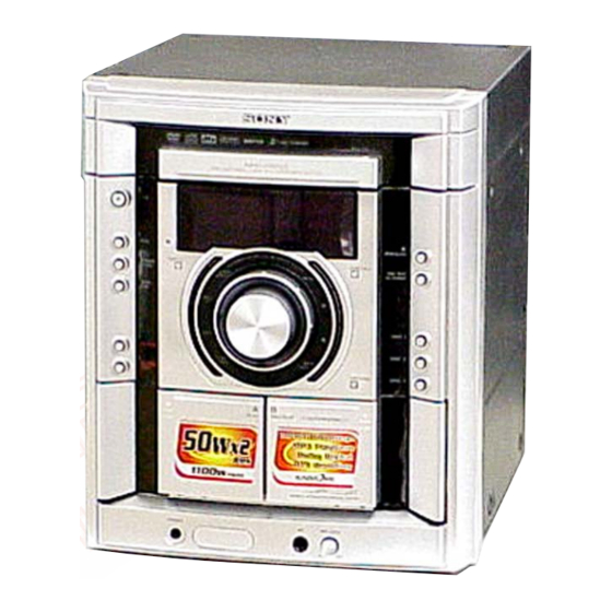
• HCD-GNZ5D is the tuner, deck,
DVD and amplifier section in
MHC-GNZ5D.
TE
L 13942296513
Amplifier section
The following measured at AC 120, 220, 230 – 240 V,
50/60 Hz
Continuous RMS power output (reference)
50 + 50 watts
(6 ohms at 1 kHz, 10%
THD)
Inputs
MIC (phone jack):
sensitivity 1 mV,
impedance 10 kilohms
Outputs
VIDEO OUT (phono jack):
max. output level
1 Vp-p, unbalanced, Sync
negative, load impedance
75 ohms
DIGITAL OPTICAL OUT (Square optical connector jack,
rear panel)
Wavelength
660 nm
PHONES (stereo mini jack):
accepts headphones of
8 ohms or more
FRONT SPEAKER:
Use only the supplied
speaker SS-GNZ5D
www
.
Sony Corporation
9-879-821-02
2005L04-1
Home Audio Division
© 2005. 12
Published by Sony Engineering Corporation
http://www.xiaoyu163.com
DVD
Section
Tape Deck Model Name Using Similar Machanism
Section
x
ao
u163
y
i
http://www.xiaoyu163.com
HCD-GNZ5D
2 9
8
Model Name Using Similar Mechanism
DVD Mechanism Type
Optical Pick-up Name
Tape Transport Mechanism Type
Q Q
3
6 7
1 3
1 5
SPECIFICATIONS
Disc player section
System
Laser
Frequency response
Video color system format
Tape deck section
Recording system
Frequency response
co
.
9 4
2 8
E Model
HCD-GNZ7D/GNZ8D/GNZ9D
CDM74HF-DVBU101//C
KHM-310CAB/C2NP
HCD-GNZ7D/GNZ8D/GNZ9D
CWM43FR601
0 5
8
2 9
9 4
2 8
Compact disc and digital
audio and video system
Semiconductor laser
(DVD: λ=650 nm,
CD: λ=790 nm)
Emission duration:
continuous
DVD (PCM 48 kHz):
2 Hz – 22 kHz (±1 dB)
CD: 2 Hz – 20 kHz (±1 dB)
NTSC, PAL
4-track 2-channel stereo
40 – 13,000 Hz (±3 dB),
using Sony TYPE I
cassette
– Continued on next page –
m
DVD DECK RECEIVER
9 9
9 9
1
Advertisement
Table of Contents

Related Manuals for Sony HCD-GNZ5D


Summary of Contents for Sony HCD-GNZ5D
- Page 1 HCD-GNZ5D 3 7 63 1515 0 SERVICE MANUAL E Model Ver. 1.1 2005. 12 • HCD-GNZ5D is the tuner, deck, DVD and amplifier section in MHC-GNZ5D. Model Name Using Similar Mechanism HCD-GNZ7D/GNZ8D/GNZ9D DVD Mechanism Type CDM74HF-DVBU101//C Section Optical Pick-up Name...
- Page 2 COMPONENTS IDENTIFIED BY MARK 0 OR DOTTED LINE WITH MARK 0 ON THE SCHEMATIC DIAGRAMS AND IN THE PARTS LIST ARE CRITICAL TO SAFE OPERATION. REPLACE THESE COMPONENTS WITH SONY PARTS WHOSE PART NUMBERS APPEAR AS SHOWN IN THIS MANUAL OR IN SUPPLEMENTS PUBLISHED BY SONY.
- Page 3 HCD-GNZ5D Ver. 1.1 3 7 63 1515 0 Notes on Chip Component Replacement NOTES ON LASER DIODE EMISSION CHECK • Never reuse a disconnected chip component. The laser beam on this model is concentrated so as to be focused on •...
- Page 4 HCD-GNZ5D 3 7 63 1515 0 MODEL IDENTIFICATION • Abbreviation : 240 V AC area in E model – BACK PANEL – E12 : 220 – 240 V AC area in E model E13 : 220 – 230 V AC area in E model...
-
Page 5: Table Of Contents
HCD-GNZ5D 3 7 63 1515 0 TABLE OF CONTENTS 1. SERVICE NOTE 7. DIAGRAMS 1-1. Service Position of CDM ............ 6 7-1. Circuit Boards Location ............ 26 1-2. Service Position of DMB11 Board, Video Board ....6 7-2. Block Diagram — RF/Servo Section — ......27 1-3. -
Page 6: Service Note
HCD-GNZ5D SECTION 1 SERVICE NOTE 3 7 63 1515 0 1-1. SERVICE POSITION OF CDM DVD mechanism block stand L 13942296513 1-2. SERVICE POSITION OF DMB11 BOARD, VIDEO BOARD DMB11 board PANEL board VIDEO board J-2501-102-A u163 http://www.xiaoyu163.com... -
Page 7: Service Position Of Tcm
HCD-GNZ5D 3 7 63 1515 0 1-3. SERVICE POSITION OF TCM earth is taken L 13942296513 1-4. SERVICE POSITION OF FRONT AMP BOARD AUDIO board FRONT AMP board earth is taken u163 insulating plate http://www.xiaoyu163.com... -
Page 8: General
HCD-GNZ5D SECTION 2 GENERAL 3 7 63 1515 0 This section is extracted from instruction manual. List of button locations and reference pages How to use this page Illustration number Use this page to find the location of buttons and other... -
Page 9: Remote Control
HCD-GNZ5D 3 7 63 1515 0 Remote control ALPHABETICAL ORDER BUTTON DESCRIPTIONS A — Q R — Z ?/1 (power) 1 (8, 45, 56) TV ?/1 1 (50) ALBUM +/– wf (11, 50) REPEAT ws (15) REPLAY/ADVANCE ANGLE 5 (34) -
Page 10: Disassembly
HCD-GNZ5D SECTION 3 DISASSEMBLY 3 7 63 1515 0 Note : Disassemble the unit in the order as shown below. 3-1. CASE (Page 11) 3-5. TAPE MECHANISM DECK SECTION (Page 13) 3-2. LOADING PANEL ASSY (Page 11) 3-7. JACK BOARD 3-6. -
Page 11: Case
HCD-GNZ5D 3 7 63 1515 0 Note : Follow the disassembly procedure in the numerical order given. 3-1. CASE qa two screws 6 screw 8 screw (+BVTT 3 × 6) (+BVTT 3 × 6) (case 3 TP2) 0 case (side-R) qs two screws (+BVTP 3 ×... -
Page 12: Front Panel Section
HCD-GNZ5D 3 7 63 1515 0 3-3. FRONT PANEL SECTION 2 CN102 (13 core) 1 CN005 (13 core) 8 CN755 (4P) 3 screw (+BVTP 3 × 10) 7 CN752 (27 core) 9 CN203 (4P) 0 CN751 (10P) 4 screw (+BVTP 3 ×... -
Page 13: Tape Mechanism Deck Section
HCD-GNZ5D 3 7 63 1515 0 3-5. TAPE MECHANISM DECK SECTION 4 two screws (+BVTP 2.6 (3CR)) 6 screw (+BVTP 2.6 (3CR)) 2 screw (+BVTP 2.6 (3CR)) 3 GUARD board 5 two screws (+BVTP 2.6 (3CR)) clamp 7 tape mechanism deck... -
Page 14: Jack Board
HCD-GNZ5D 3 7 63 1515 0 3-7. JACK BOARD 2 two screws (+BVTP 2.6 (3CR)) 4 bracket (TC-JACK) 5 JACK board 3 two screws (+BVTT 3 × 6) 1 mic knob L 13942296513 3-8. BACK PANEL SECTION 8 back panel section 3 two screws (+BVTT 3 ×... -
Page 15: Boards Section
HCD-GNZ5D 3 7 63 1515 0 3-9. BOARDS SECTION 4 two screws (+BV sumitite (B3)) 5 two screws (+BV sumitite (B3)) 6 boards section 1 CN915 (4P) 3 two screws (+BVTT 3 × 6) 2 CN914 (10P) L 13942296513 3-10. -
Page 16: Dvd Mechanism Block, Video Board, Dmb11 Board
HCD-GNZ5D 3 7 63 1515 0 3-11. DVD MECHANISM BLOCK, VIDEO BOARD, DMB11 BOARD qk DVD mechanism block qj bracket (DVD) qg screw (+BVTP 3 × 8) 7 REINFORCE (CDM) board 6 three screws (+BVTT 3 × 6) qf screw (+BVTP 3 ×... -
Page 17: Sw Board, Driver Board
HCD-GNZ5D 3 7 63 1515 0 3-13. SW BOARD, DRIVER BOARD 7 CN702 (flat type) 4 CN703 6 DRIVER board 2 SW board 3 CN704 1 screw 5 two screws (+BTTP (M2.6)) (+BTTP (M2.6)) L 13942296513 3-14. SENSOR BOARD 1 floating screw (+PTPWH M2.6) -
Page 18: Motor (Tb) Board
HCD-GNZ5D 3 7 63 1515 0 3-15. MOTOR (TB) BOARD 2 stopper table assy 2 stopper 6 table motor assy (M741) 4 MOTOR (TB) board 5 Remove the two solders of motor. 3 two screws (+BTTP (M2.6)) L 13942296513 3-16. -
Page 19: Test Mode
HCD-GNZ5D SECTION 4 TEST MODE 3 7 63 1515 0 [Cold Reset] VACS Display • The cold reset clears all data including preset data stored in the Procedure: RAM to initial conditions. Execute this mode when returning 1. It puts it into the start of the panel test mode. -
Page 20: General Description
HCD-GNZ5D Ver. 1.1 3 7 63 1515 0 DVD SECTION 4-4. MIRROR TIME ADJUSTMENT [TEST DISC LIST] To enter Mirror Time Adjustment, press 5 “R” button on the remote Be sure to use the DVD disc that matches the signal standards of commander. - Page 21 HCD-GNZ5D 3 7 63 1515 0 (14) Confirm the same values are displayed. If it is not same, (3) Select “5. MIRR time Adjust”. return to step 7. Drive Manual Operation MIRR time Adjust Menu 1. Servo Control 2. Track/Layer Jump 1.
-
Page 22: Executing Iop Measurement
HCD-GNZ5D 3 7 63 1515 0 4-5. EXECUTING IOP MEASUREMENT (5) Wait until a hexadecimal number appear. Manual Adjust In order to execute mirror time adjustment, the following standard procedures must be followed. 1. Track Balance Adjust: 2. Track Gain Adjust: (1) In standby mode, press three buttons x , A and 3. -
Page 23: Mechanical Adjustments
HCD-GNZ5D SECTION 5 MECHANICAL ADJUSTMENTS 3 7 63 1515 0 Precaution 1. Clean the following parts with a denatured alcohol-moistened swab: record/playback heads pinch rollers erase head rubber belts capstan idlers 2. Demagnetize the record/playback head with a head demagnetizer. -
Page 24: Electrical Adjustments
HCD-GNZ5D Ver. 1.1 SECTION 6 ELECTRICAL ADJUSTMENTS 3 7 63 1515 0 Checking Location: DMB10 board (Side A) DVD SECTION When the base unit is replaced, perform the adjustment and the measurement as shown below in this order. 1) MIRROR TIME ADJUSTMENT (See page 20) - Page 25 HCD-GNZ5D Ver. 1.1 3 7 63 1515 0 3. Mode: Playback DECK SECTION 0 dB=0.775 V test tape 1. Demagnetize the record/playback head with a head P-4-A063 demagnetizer. oscilloscope (6.3 kHz, –10 dB) 2. Do not use a magnetized screwdriver for the adjustments.
-
Page 26: Diagrams
HCD-GNZ5D SECTION 7 DIAGRAMS 3 7 63 1515 0 7-1. CIRCUIT BOARDS LOCATION SW board SENSOR board DMB11 board VIDEO board MOTOR (LD) board TRANS board MOTOR (TB) board SIRCS board OPTICAL board DRIVER board PANEL board POWER SWITCHING... -
Page 27: Block Diagram - Rf/Servo Section
HCD-GNZ5D 3 7 6 3 1 5 1 5 0 7-2. BLOCK DIAGRAM — RF/SERVO SECTION — DVDRFIP DVDA DVDB DETECTOR DVDC DVDD 8 NA 9 NB CD/DVD RF AMP, FOCUS/TRACKING ERROR AMP DVD SYSTEM PROCESSOR OPTICAL PICK-UP DIGITAL SERVO PROCESSOR •... -
Page 28: Block Diagram - Video Section
HCD-GNZ5D 3 7 6 3 1 5 1 5 0 7-3. BLOCK DIAGRAM — VIDEO SECTION — VIDEO AMP IC801 J801 VIDEO YUV3 4 IN MAIN VIDEO MUTE SECTION (Page 29) D/A CONVERTER IC301 14 SDTI1 ASDAT0 15 SDTI2... -
Page 29: Block Diagram - Main Section
HCD-GNZ5D 3 7 6 3 1 5 1 5 0 7-4. BLOCK DIAGRAM — MAIN SECTION — REC/PB AMP, SOUND CONTROLLER OVERHEAT IC201 TH401,Q416,417 FRONT L Q272 POWER AMP VIDEO SUR1 DOWN MIX L TM901 IC401 SECTION TM401 (Page 28) -
Page 30: Block Diagram - Function/Power Section
HCD-GNZ5D 3 7 6 3 1 5 1 5 0 7-5. BLOCK DIAGRAM — FUNCTION/POWER SECTION — MAIN HP SW SECTION POWER SYSTEM CONTROL (Page 29) CONTROL IC101 (3/3) D +3.3V D +3.3V Q108,109 E3,E15,PH MODEL S11,12,14-20 S901 T911... - Page 31 HCD-GNZ5D 3 7 6 3 1 5 1 5 0 • NOTE FOR PRINTED WIRING BOARDS AND SCHEMATIC DIAGRAMS • WAVEFORMS – DMB11 BOARD – Note on Printed Wiring Board: Note on Schematic Diagram: • X : parts extracted from the component side.
-
Page 32: Printed Wiring Boards - Driver Section
HCD-GNZ5D 3 7 6 3 1 5 1 5 0 7-6. PRINTED WIRING BOARDS — DRIVER SECTION — • Refer to page 26 for Circuit Boards Location. : Uses unleaded solder. 1 3 9 4 2 2 9 6 5 1 3... -
Page 33: Schematic Diagram - Driver Section
HCD-GNZ5D 3 7 6 3 1 5 1 5 0 7-7. SCHEMATIC DIAGRAM — DRIVER SECTION — • Refer to page 56 for IC Block Diagrams. IC701 IC B/D R702 R701 D701 C715 CN721 CN704 C751 M751 IC712 1 3 9 4 2 2 9 6 5 1 3... -
Page 34: Printed Wiring Board - Dmb11 Section
HCD-GNZ5D Ver. 1.1 3 7 6 3 1 5 1 5 0 7-8. PRINTED WIRING BOARD — DMB11 SECTION — • Refer to page 26 for Circuit Boards Location. : Uses unleaded solder. • Semiconductor Location Ref. No. Location... - Page 35 HCD-GNZ5D 3 7 6 3 1 5 1 5 0 1 3 9 4 2 2 9 6 5 1 3 w w w u 1 6 3 (11) 1-865-736- HCD-GNZ5D http://www.xiaoyu163.com...
-
Page 36: Schematic Diagram - Dmb11 Section (1/4)
HCD-GNZ5D 3 7 6 3 1 5 1 5 0 7-9. SCHEMATIC DIAGRAM — DMB11 SECTION (1/4) — • Refer to page 56 for IC Block Diagrams. R3501 R3781 R3783 (Page 38) ICT301 C3781 R3784 C3782 R3787 R3788 CN302... -
Page 37: Schematic Diagram - Dmb11 Section (2/4)
HCD-GNZ5D 3 7 6 3 1 5 1 5 0 7-10. SCHEMATIC DIAGRAM — DMB11 SECTION (2/4) — (Page 38) (Page (Page 39) R223 R225 C209 R230 C211 (Page 39) R234 C233 R221 C212 C215 R220 (Page 39) R233... -
Page 38: Schematic Diagram - Dmb11 Section (3/4)
HCD-GNZ5D 3 7 6 3 1 5 1 5 0 • Refer to page 59 for IC Pin Descriptions. 7-11. SCHEMATIC DIAGRAM — DMB11 SECTION (3/4) — • Refer to page 31 for Waveforms. (Page 36) (Page 36) (Page 39) -
Page 39: Schematic Diagram - Dmb11 Section (4/4)
HCD-GNZ5D Ver. 1.1 3 7 6 3 1 5 1 5 0 New part of EEP ROM (IC103) on the DMB11 board cannot be used. Therefore, 7-12. SCHEMATIC DIAGRAM — DMB11 SECTION (4/4) — if the mounted DMB11 board (A-1109-317-A, etc.) is replaced, exchange new EEP ROM (IC103) with that used before the replacement. -
Page 40: Printed Wiring Boards - Audio Section
HCD-GNZ5D 3 7 6 3 1 5 1 5 0 7-13. PRINTED WIRING BOARDS — AUDIO SECTION — • Refer to page 26 for Circuit Boards Location. : Uses unleaded solder. (Page 34) TM901 JACK BOARD NO1002 CN755 (Page 51) -
Page 41: Schematic Diagram - Audio Section (1/3)
HCD-GNZ5D 3 7 6 3 1 5 1 5 0 7-14. SCHEMATIC DIAGRAM — AUDIO SECTION (1/3) — R304 IC306 C325 NO305 CN304 FB301 R323 C323 C321 R321 R322 C322 L302 C365 C308 C309 C361 R361 R362 C362 R363... -
Page 42: Schematic Diagram - Audio Section (2/3)
HCD-GNZ5D 3 7 6 3 1 5 1 5 0 7-15. SCHEMATIC DIAGRAM — AUDIO SECTION (2/3) — (Page 41) NO703 C367 C368 CN203 (Page 45) (Page 52) C657 R656 R231 R252 C261 R658 Q282 R282 R253 C260 IC201... -
Page 43: Schematic Diagram - Audio Section (3/3)
HCD-GNZ5D 3 7 6 3 1 5 1 5 0 7-16. SCHEMATIC DIAGRAM — AUDIO SECTION (3/3) — (Page 42) CN202 IC771 Q771 CN752 (Page 47) Q772 R751 C772 C771 R753 R752 D753 R763 R762 1 3 9 4 2 2 9 6 5 1 3... -
Page 44: Printed Wiring Board - Video Section
HCD-GNZ5D 3 7 6 3 1 5 1 5 0 7-17. PRINTED WIRING BOARD — VIDEO SECTION — • Refer to page 26 for Circuit Boards Location. : Uses unleaded solder. (Page 34) (Page 34) DMB11 BOARD CN401 DMB11 BOARD CN301... -
Page 45: Schematic Diagram - Video Section
HCD-GNZ5D 3 7 6 3 1 5 1 5 0 7-18. SCHEMATIC DIAGRAM — VIDEO SECTION — CN851 NO851 C872 IC851 C856 (Page 42) C853 (Page 37) C854 C851 C866 IC861 R871 Q861 R861 R870 L862 Q870 L861 D861... -
Page 46: Printed Wiring Board - Front Amp Section
HCD-GNZ5D 3 7 6 3 1 5 1 5 0 7-19. PRINTED WIRING BOARD — FRONT AMP SECTION — • Refer to page 26 for Circuit Boards Location. : Uses unleaded solder. (Page 40) (Page 40) AUDIO BOARD AUDIO BOARD... -
Page 47: Schematic Diagram - Front Amp Section
HCD-GNZ5D 3 7 6 3 1 5 1 5 0 7-20. SCHEMATIC DIAGRAM — FRONT AMP SECTION — IC401 R418 R417 Q417 R421 R416 IC945 R412 Q416 R414 C410 C950 C949 R415 NO471 R413 D471 C471 CN402 R471 TH401... -
Page 48: Schematic Diagram - Panel Section (1/2)
HCD-GNZ5D 3 7 6 3 1 5 1 5 0 7-21. SCHEMATIC DIAGRAM — PANEL SECTION (1/2) — R050 R049 R048 R047 R046 R045 R044 R043 R042 R041 D111 R068 R067 R066 R065 R064 R071 R070 R063 R062 R061... -
Page 49: Schematic Diagram - Panel Section (2/2)
HCD-GNZ5D 3 7 6 3 1 5 1 5 0 • Refer to page 57 for IC Pin Descriptions. 7-22. SCHEMATIC DIAGRAM — PANEL SECTION (2/2) — • Refer to page 31 for Waveforms. (Page 48) R174 C121 C126... -
Page 50: Printed Wiring Boards - Panel Section
HCD-GNZ5D 3 7 6 3 1 5 1 5 0 7-23. PRINTED WIRING BOARDS — PANEL SECTION — • Refer to page 26 for Circuit Boards Location. : Uses unleaded solder. (Page 32) (Page 34) DRIVER BOARD DMB11 BOARD... -
Page 51: Printed Wiring Board - Jack Section
HCD-GNZ5D 3 7 6 3 1 5 1 5 0 7-24. PRINTED WIRING BOARD — JACK SECTION — • Refer to page 26 for Circuit Boards Location. : Uses unleaded solder. (Page 40) (Page 40) AUDIO BOARD AUDIO BOARD... -
Page 52: Schematic Diagram - Jack Section
HCD-GNZ5D 3 7 6 3 1 5 1 5 0 7-25. SCHEMATIC DIAGRAM — JACK SECTION — JR1000 IC1001(2/2) R1011 C1006 R1014 C1011 R1020 R1019 C1014 C1005 R1012 C1009 C1010 R1015 R1008 J1002 C1008 C1013 RV1001 R1013 IC1001(1/2) NO1001... -
Page 53: Schematic Diagram - Power Section
HCD-GNZ5D 3 7 6 3 1 5 1 5 0 7-26. SCHEMATIC DIAGRAM — POWER SECTION — S901 F910 F914 CN915 FH911 FH910 T911 JW921 FH918 FH917 NO911 NO902 (Page 47) F915 JW925 JW923 JW910 JW901 FH920 FH919 F918... -
Page 54: Printed Wiring Board - Trans Section
HCD-GNZ5D 3 7 6 3 1 5 1 5 0 7-27. PRINTED WIRING BOARD — TRANS SECTION — • Refer to page 26 for Circuit Boards Location. : Uses unleaded solder. (CHASSIS) SUB TRANS FRONT AMP BOARD BOARD NO902... -
Page 55: Printed Wiring Board - Sub Trans Section
HCD-GNZ5D 3 7 6 3 1 5 1 5 0 7-28. PRINTED WIRING BOARD — SUB TRANS SECTION — • Refer to page 26 for Circuit Boards Location. : Uses unleaded solder. (CHASSIS) JW902 LP903 L901 TRANS BOARD NO912... - Page 56 HCD-GNZ5D 3 7 6 3 1 5 1 5 0 • IC BLOCK DIAGRAMS IC701 BA6956AN (DRIVER Board) IC801 MM1671XNRE (VIDEO Board) IC712 BA6956AN (DRIVER Board) CLAMP 75Ω DRIVER 6.75MHz CONTROL LOGIC 1 3 9 4 2 2 9 6 5 1 3...
- Page 57 HCD-GNZ5D 3 7 63 1515 0 • IC PIN Descriptions IC101 M30392MEP-A10FPU0 (SYSTEM CONTROL) (PANEL BOARD (2/2)) Pin No. Pin Name Pin Description 61537 CLK TA device control serial clock signal output 61530 CLK TA device control serial clock signal output...
- Page 58 HCD-GNZ5D 3 7 63 1515 0 Pin No. Pin Name Pin Description SHUT (A) Protect detect signal input (A deck) SHUT (B) Protect detect signal input (B deck) B HALF/REC B deck HALF signal input/Record signal input (A deck and B deck)
- Page 59 HCD-GNZ5D 3 7 63 1515 0 IC102 CXD9849R (DMB11 BOARD (3/4)) (CD/DVD RF AMP, FOCUS/TRACKING ERR AMP, DVD SYSTEM PROCESSOR, DIGITAL SERVO PROCESSOR) Pin No. Pin Name Description AGND — Terminal Ground DVDA AC coupled input path A DVDB...
- Page 60 HCD-GNZ5D 3 7 63 1515 0 Pin No. Pin Name Description DSEL Select signal output WIDE SI signal output to VIDEO AMP Volume control signal output to Optical pick-up MAMUTE MAMUTE signal output to System Controller (IC509) (not used) DVDD18 —...
- Page 61 HCD-GNZ5D 3 7 63 1515 0 Pin No. Pin Name Description MREQ DQM signal input Data bus 7 from SD-RAM (IC104) DVSS — Terminal Ground 117, 118 RD 6, 5 Data bus 6, 5 from SD-RAM (IC104) DVSS —...
- Page 62 HCD-GNZ5D 3 7 63 1515 0 Pin No. Pin Name Description OCSW SEN signal input from System Controller (IC509)/OCSW signal input REV signal output to Motor driver (IC201) Not used. (Open) CKSW CKSW signal input Not used. (Open) —...
- Page 63 HCD-GNZ5D 3 7 63 1515 0 Pin No. Pin Name Description RFVDD18 — Power Supply (+1.8V) ZTALO Oscillator output signal ZTALI Oscillator input signal JITFO RF jitter meter output JITFN Negative input of operation amplifier for RF jigger meter PLLVSS —...
-
Page 64: Exploded Views
HCD-GNZ5D SECTION 8 EXPLODED VIEWS 3 7 63 1515 0 NOTE: • The mechanical parts with no reference • Abbreviation The components identified by mark 0 or dotted line with mark number in the exploded views are not supplied. -
Page 65: Front Panel Section (1)
HCD-GNZ5D 3 7 63 1515 0 8-2. FRONT PANEL SECTION (1) not supplied (SIRCS board) FL101 not supplied not supplied not supplied not supplied L 13942296513 not supplied Ref. No. Part No. Description Remark Ref. No. Part No. Description... -
Page 66: Front Panel Section (2)
HCD-GNZ5D 3 7 63 1515 0 8-3. FRONT PANEL SECTION (2) not supplied L 13942296513 not supplied not supplied Ref. No. Part No. Description Remark Ref. No. Part No. Description Remark 4-231-836-01 SPRING (HEART CAM-A) 2-582-707-01 LID (A), CASSETTE... -
Page 67: Front Panel Section (3)
Ref. No. Part No. Description Remark 2-582-706-12 PANEL, FRONT 2-590-671-12 KNOB (VOL) 3-087-053-01 +BVTP 2.6 (3CR) 3-038-018-01 EMBLEM, SONY 4-233-980-01 RUBBER FOOT 2-582-716-01 ESCUTCHEON (JOG) 2-582-719-01 ESCUTCHEON (PANEL) 2-582-717-01 ORNAMENT (PLAY) 2-582-715-01 RING (JOG) 2-582-719-21 ESCUTCHEON (PANEL) 2-582-714-01 INDICATOR (JOG) -
Page 68: Dvd Block Section
HCD-GNZ5D 3 7 63 1515 0 8-5. DVD BLOCK SECTION CDM74HF not supplied not supplied not supplied not supplied L 13942296513 supplied supplied not supplied Ref. No. Part No. Description Remark Ref. No. Part No. Description Remark A-1109-328-A VIDEO BOARD, COMPLETE... -
Page 69: Chassis Section
HCD-GNZ5D 3 7 63 1515 0 8-6. CHASSIS SECTION not supplied (TRANS board) not supplied F919 T911 L 13942296513 F918 F915 F914 F910 not supplied not supplied (SUB TRANS board) Ref. No. Part No. Description Remark Ref. No. Part No. -
Page 70: Audio Board Section
HCD-GNZ5D 3 7 63 1515 0 8-7. AUDIO BOARD SECTION not supplied IC401 IC941 IC942 IC943 IC945 not supplied (LEAD PIN board) not supplied L 13942296513 Ref. No. Part No. Description Remark Ref. No. Part No. Description Remark A-1109-313-A AUDIO BOARD, COMPLETE... -
Page 71: Dvd Mechanism Deck Section (1)
HCD-GNZ5D 3 7 63 1515 0 8-8. DVD MECHANISM DECK SECTION (1) L 13942296513 M741 chassis assy Ref. No. Part No. Description Remark Ref. No. Part No. Description Remark 4-218-253-62 SCREW (M2.6), +BTTP 4-243-820-01 GEAR (TABLE) 1-776-182-11 WIRE (FLAT TYPE) (5 CORE) -
Page 72: Dvd Mechanism Deck Section (2)
HCD-GNZ5D 3 7 63 1515 0 8-9. DVD MECHANISM DECK SECTION (2) not supplied RE701 not supplied M751 L 13942296513 not supplied not supplied Ref. No. Part No. Description Remark Ref. No. Part No. Description Remark A-1103-756-A DRIVER BOARD, COMPLETE 4-224-606-01 GEAR (RV) 4-218-253-52 SCREW (M2.6), +BTTP... -
Page 73: Electrical Parts List
HCD-GNZ5D SECTION 9 AUDIO ELECTRICAL PARTS LIST 3 7 63 1515 0 NOTE: • Due to standardization, replacements in • Items marked “*” are not stocked since The components identified by mark 0 or dotted line with mark the parts list may be different from the they are seldom required for routine service. - Page 74 HCD-GNZ5D AUDIO 3 7 63 1515 0 Ref. No. Part No. Description Remark Ref. No. Part No. Description Remark C659 1-136-497-81 FILM 0.1uF IC771 6-703-547-01 IC TA7805LS C725 1-107-696-11 ELECT 47uF C726 1-107-696-11 ELECT 47uF < JUMPER RESISTOR >...
- Page 75 HCD-GNZ5D AUDIO 3 7 63 1515 0 Ref. No. Part No. Description Remark Ref. No. Part No. Description Remark R212 1-216-829-11 METAL CHIP 4.7K 1/10W R617 1-216-835-11 METAL CHIP 1/10W R213 1-216-833-11 METAL CHIP 1/10W R618 1-216-823-11 METAL CHIP 1.5K...
- Page 76 HCD-GNZ5D Ver. 1.1 DMB11 3 7 63 1515 0 Ref. No. Part No. Description Remark Ref. No. Part No. Description Remark A-1109-316-A DMB11 BOARD, COMPLETE (PH) C167 1-162-970-11 CERAMIC CHIP 0.01uF A-1109-317-A DMB11 BOARD, COMPLETE (EXCEPT PH) C170 1-162-970-11 CERAMIC CHIP 0.01uF...
- Page 77 HCD-GNZ5D Ver. 1.1 DMB11 3 7 63 1515 0 Ref. No. Part No. Description Remark Ref. No. Part No. Description Remark C3721 1-162-977-11 CERAMIC CHIP 0.0018uF 10% < IC > C3722 1-162-967-11 CERAMIC CHIP 0.0033uF 10% C3723 1-162-964-11 CERAMIC CHIP 0.001uF...
- Page 78 HCD-GNZ5D DMB11 3 7 63 1515 0 Ref. No. Part No. Description Remark Ref. No. Part No. Description Remark R164 1-216-809-11 METAL CHIP 1/10W R1502 1-216-864-11 SHORT CHIP R169 1-216-833-11 METAL CHIP 1/10W R1504 1-216-864-11 SHORT CHIP R187 1-216-864-11 SHORT CHIP...
- Page 79 HCD-GNZ5D DMB11 DRIVER FRONT AMP 3 7 63 1515 0 Ref. No. Part No. Description Remark Ref. No. Part No. Description Remark R3788 1-216-829-11 METAL CHIP 4.7K 1/10W IC712 8-759-598-69 IC BA6956AN R3789 1-216-821-11 METAL CHIP 1/10W R3801 1-216-864-11 SHORT CHIP <...
- Page 80 HCD-GNZ5D FRONT AMP JACK 3 7 63 1515 0 Ref. No. Part No. Description Remark Ref. No. Part No. Description Remark < CONNECTOR > R453 1-247-812-11 CARBON 1/4W R454 1-247-871-11 CARBON 1/4W CN401 1-573-829-11 CONNECTOR, BOARD TO BOARD 15P...
- Page 81 HCD-GNZ5D JACK MOTOR (LD) MOTOR (TB) OPTICAL PANEL 3 7 63 1515 0 Ref. No. Part No. Description Remark Ref. No. Part No. Description Remark < IC > A-1141-196-A PANEL BOARD, COMPLETE ********************** IC1001 8-759-710-97 IC NJM4565M-D < CAPACITOR >...
- Page 82 HCD-GNZ5D PANEL 3 7 63 1515 0 Ref. No. Part No. Description Remark Ref. No. Part No. Description Remark D113 6-501-193-01 DIODE 1SS355WTE-17 R011 1-216-809-11 METAL CHIP 1/10W D114 6-501-193-01 DIODE 1SS355WTE-17 R012 1-216-809-11 METAL CHIP 1/10W D121 6-501-193-01 DIODE 1SS355WTE-17...
- Page 83 HCD-GNZ5D PANEL 3 7 63 1515 0 Ref. No. Part No. Description Remark Ref. No. Part No. Description Remark R070 1-216-819-11 METAL CHIP 1/10W R128 1-216-809-11 METAL CHIP 1/10W R071 1-216-821-11 METAL CHIP 1/10W R129 1-216-809-11 METAL CHIP 1/10W...
- Page 84 HCD-GNZ5D PANEL SENSOR SIRCS STREAM SUB TRANS 3 7 63 1515 0 Ref. No. Part No. Description Remark Ref. No. Part No. Description Remark R187 1-216-809-11 METAL CHIP 1/10W < CONNECTOR > R188 1-216-809-11 METAL CHIP 1/10W R189 1-216-809-11 METAL CHIP...
- Page 85 HCD-GNZ5D SUB TRANS TRANS VIDEO 3 7 63 1515 0 Ref. No. Part No. Description Remark Ref. No. Part No. Description Remark < TRANSISTOR > A-1109-328-A VIDEO BOARD, COMPLETE ********************** Q901 8-729-119-78 TRANSISTOR 2SC2785-HFE < CAPACITOR > < RESISTOR >...
- Page 86 HCD-GNZ5D VIDEO 3 7 63 1515 0 Ref. No. Part No. Description Remark R870 1-247-807-31 CARBON 1/4W R871 1-249-429-11 CARBON 1/4W ************************************************************* MISCELLANEOUS *************** 1-828-956-11 WIRE (FLAT TYPE) (9 CORE) 1-828-977-11 WIRE (FLAT TYPE) (13 CORE) 1-828-971-11 WIRE (FLAT TYPE) (13 CORE)
- Page 87 HCD-GNZ5D 3 7 63 1515 0 MEMO L 13942296513 u163 http://www.xiaoyu163.com...
- Page 88 HCD-GNZ5D 3 7 63 1515 0 REVISION HISTORY Clicking the version allows you to jump to the revised page. Also, clicking the version at the upper on the revised page allows you to jump to the next revised page.
Need help?
Do you have a question about the HCD-GNZ5D and is the answer not in the manual?
Questions and answers