Table of Contents
Advertisement
HCD-GNZ7D/GNZ8D/GNZ9D
QQ
3 7 63 1515 0
SERVICE MANUAL
Ver. 1.1 2005. 12
• HCD-GNZ7D/GNZ8D/GNZ9D are
the tuner, deck, DVD and amplifier
section in MHC-GNZ7D/GNZ8D/
GNZ9D.
TE
L 13942296513
Amplifier section
HCD-GNZ9D
The following measured at AC 120, 127, 220, 230 – 240 V,
50/60 Hz
Continuous RMS power output (reference)
Front speaker:
115 + 115 watts
(6 ohms at 1 kHz, 10%
THD)
Center speaker:
50 watts (6 ohms at 1 kHz,
10% THD)
Surround speaker:
50 + 50 watts
(6 ohms at 1 kHz, 10%
THD)
Subwoofer:
170 watts (4 ohms at
100 Hz, 10% THD)
HCD-GNZ8D
The following measured at AC 120, 127, 220, 230 – 240 V,
50/60 Hz
Continuous RMS power output (reference)
Front speaker:
100 + 100 watts
(6 ohms at 1 kHz, 10%
THD)
Center speaker:
40 watts (6 ohms at 1 kHz,
10% THD)
Surround speaker:
40 + 40 watts
(6 ohms at 1 kHz, 10%
THD)
HCD-GNZ7D
The following measured at AC 120, 127, 220, 230 – 240 V,
50/60 Hz
Continuous RMS power output (reference)
100 + 100 watts
www
(6 ohms at 1 kHz, 10%
THD)
.
Sony Corporation
9-879-622-02
2005L04-1
Home Audio Division
© 2005. 12
Published by Sony Engineering Corporation
http://www.xiaoyu163.com
x
ao
u163
y
i
http://www.xiaoyu163.com
2 9
8
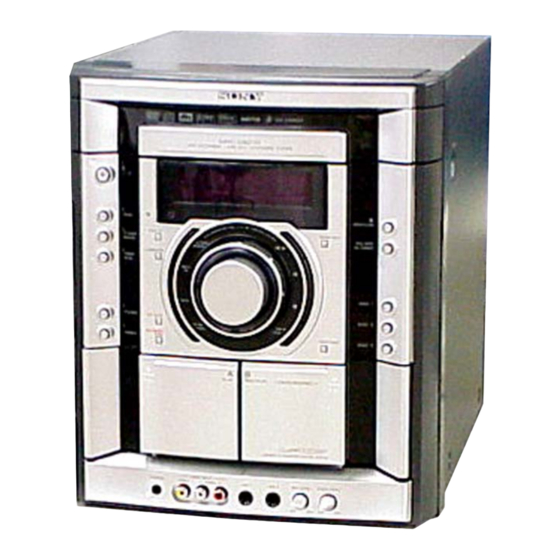
(Photo: HCD-GNZ7D)
Model Name Using Similar Mechanism
DVD
DVD Mechanism Type
Section
Optical Pick-up Name
Tape Deck
Model Name Using Similar Machanism
Section
Q Q
3
6 7
1 3
1 5
SPECIFICATIONS
Inputs
VIDEO/SAT IN (audio) (phono jacks):
VIDEO INPUT VIDEO (phono jack):
VIDEO INPUT AUDIO (phono jacks):
MIC1/MIC2 (phone jack):
Outputs
VIDEO/SAT OUT (audio) (phono jacks):
VIDEO OUT (phono jack):
S-VIDEO OUT (4-pin/mini-DIN jack):
COMPONENT VIDEO OUT:
co
.
9 4
2 8
E Model
HCD-GNZ7D/GNZ8D/GNZ9D
Australian Model
NEW
CDM74HF-DVBU101//C
KHM-310CAB/C2NP
NEW
0 5
8
2 9
9 4
2 8
voltage 450/250 mV,
impedance 47 kilohms
1 Vp-p, 75 ohms
voltage 250 mV,
impedance 47 kilohms
sensitivity 1 mV,
impedance 10 kilohms
voltage 250 mV,
impedance 1 kilohm
max. output level
1 Vp-p, unbalanced, Sync
negative, load impedance
75 ohms
Y: 1 Vp-p, unbalanced,
Sync negative,
C: 0.286 Vp-p, load
impedance 75 ohms
Y: 1 Vp-p, 75 ohms
P
, P
: 0.7 Vp-p, 75 ohms
B
R
– Continued on next page –
m
DVD DECK RECEIVER
9 9
HCD-GNZ9D
9 9
1
Advertisement
Table of Contents

Related Manuals for Sony HCD-GNZ8D


Summarization of Contents
Amplifier Section Specifications
HCD-GNZ9D Amplifier Power Output
Details the continuous RMS power output for the HCD-GNZ9D front, center, and surround speakers.
HCD-GNZ8D Amplifier Power Output
Details the continuous RMS power output for the HCD-GNZ8D front, center, and surround speakers.
HCD-GNZ7D Amplifier Power Output
Details the continuous RMS power output for the HCD-GNZ7D front speakers.
System Specifications
Input and Output Specifications
Details input signal levels, impedances, and output signal levels for various audio/video ports.
Disc and Tape Mechanism Specifications
Lists specifications for DVD mechanism type, optical pick-up, and tape deck mechanism.
Unit Specifications Overview
Disc Player and Tape Deck Specifications
Details disc player system, laser, frequency response, and tape deck recording system.
Tuner and General Specifications
Covers tuner frequency ranges, power requirements, consumption, dimensions, and mass.
Service Precautions and Notes
Component Handling and Soldering Precautions
Provides guidance on chip component replacement, flex circuit repair, and unleaded solder.
Optical Pick-up and Laser Safety Notes
Details handling the optical pick-up block and laser diode emission safety checks.
DMB10/DMB11 Board Replacement Advice
Specific instructions for replacing DMB10 or DMB11 boards, including EEP ROM exchange.
Model Identification Details
Model and Part Number Cross-Reference
Lists various models and their corresponding part numbers for identification.
Model Abbreviation Key
Explains abbreviations used for regional model variations (E2, E3, AUS, etc.).
Service Notes - Component Locations
CDM Service Position
Illustrates the service position for the CDM (Compact Disc Mechanism).
DMB10 and Video Board Service Positions
Illustrates the service positions for the DMB10 and Video boards.
Service Notes - Component Locations
TCM Service Position
Illustrates the service position for the TCM (Tape Cassette Mechanism).
Front AMP Board Service Position
Illustrates the service position for the Front AMP board.
Service Notes - Component Locations
Subwoofer Board Service Position
Illustrates the service position for the Subwoofer board.
General Unit Information
Main Unit Control Overview
Identifies main unit controls and their page references for easy location.
Remote Control Information
Remote Control Button Identification
Lists remote control buttons and their corresponding page references.
Disassembly Procedures Overview
Disassembly Flowchart
Provides a flowchart illustrating the recommended order for unit disassembly.
Disassembly Procedures - Case and Loading Panel
Case Disassembly Steps
Details the steps and screws required for removing the unit's case.
Loading Panel Assy Disassembly Steps
Details the steps for removing the loading panel assembly, including pulley rotation.
Disassembly Procedures - Front Panel and DVD Block
Front Panel Section Disassembly Steps
Details the steps and connectors for removing the front panel section.
DVD Block Section Disassembly Steps
Details the steps and screws for removing the DVD block section.
Disassembly Procedures - Tape Mechanism and Panel Board
Tape Mechanism Section Disassembly Steps
Details the steps and connectors for removing the tape mechanism section.
Panel Board Disassembly Steps
Details the steps and claws for removing the panel board.
Disassembly Procedures - Jack Board and Back Panel
Jack Board Disassembly Steps
Details the steps for removing the jack board and mic knobs.
Back Panel Section Disassembly Steps
Details the steps and screws for removing the back panel section.
Disassembly Procedures - Boards Section and Audio Board
Boards Section Disassembly Steps
Details the steps for disassembling the main boards section.
Audio Board (HCD-GNZ8D/GNZ9D) Disassembly Steps
Details the steps for removing the Audio Board for HCD-GNZ8D/GNZ9D models.
Disassembly Procedures - Audio and Amp Boards
Audio Board (HCD-GNZ7D) Disassembly Steps
Details the steps for removing the Audio Board for the HCD-GNZ7D model.
Surround and Subwoofer Amp Board Disassembly Steps
Details the steps for removing the Surround and Subwoofer Amp boards.
Disassembly Procedures - DVD Mechanism and Pick-up Unit
DVD Mechanism, Video, and DMB10 Board Disassembly Steps
Details steps for removing DVD mechanism, Video, and DMB10 boards.
Pick-up Unit Disassembly Steps
Details steps for disassembling the optical pick-up unit.
Disassembly Procedures - SW/Driver and Sensor Boards
SW and Driver Board Disassembly Steps
Details steps for disassembling the SW and Driver boards.
Sensor Board Disassembly Steps
Details steps for disassembling the sensor board.
Disassembly Procedures - Motor Boards
Motor (TB) Board Disassembly Steps
Details steps for disassembling the Motor (TB) board.
Motor (LD) Board Disassembly Steps
Details steps for disassembling the Motor (LD) board.
Test Modes Overview
Basic Test Modes
Covers Cold Reset, Tuner, TV/SAT, Color System, Disc Tray Lock, and Progressive Change.
Advanced Test Modes
Details VACS Display, Version Display, Common Test, and Ship Modes.
DVD Section Test Mode Procedures
Test Mode General Description and Entry
Explains the purpose of test mode and how to start it.
Drive Manual Operation and Mirror Time Adjustment
Details navigation within Drive Manual Operation and how to enter Mirror Time Adjustment.
Mirror Time Adjustment Procedure
Mirror Time Adjustment Steps for CD/DVD
Provides detailed step-by-step instructions for CD and DVD mirror time adjustment.
IOP Measurement Procedure
Executing IOP Measurement Steps
Details the step-by-step process for executing IOP measurement.
Mechanical Adjustments
Adjustment Precautions and Torque Specifications
Lists precautions and torque specifications for performing mechanical adjustments.
Electrical Adjustments
Video Level and RFMON Level Checks
Procedures for checking Video Level and RFMON signal levels.
Deck Section Adjustments
Deck Section Precautions and Azimuth Adjustment
Covers deck section precautions and the head azimuth adjustment procedure.
Diagrams and Pin Descriptions
IC101 Pin Descriptions (System Control)
Lists pin names, I/O, and descriptions for IC101 on the panel board.
IC Pin Descriptions
IC102 Pin Descriptions (Signal In/Out Control)
Lists pin names, I/O, and descriptions for IC102 on the panel board.
DMB10 Board IC Pin Descriptions
IC102 CXD9804R Pin Descriptions
Details pin names, I/O, and descriptions for IC102 on the DMB10 board.
DMB10 Board IC Pin Descriptions (Continued)
IC102 CXD9804R Pin Descriptions
Continues pin descriptions for IC102 on the DMB10 board.
DMB10 Board IC Pin Descriptions (Continued)
IC102 CXD9804R Pin Descriptions
Continues pin descriptions for IC102 on the DMB10 board.
DMB10 Board IC Pin Descriptions (Continued)
IC102 CXD9804R Pin Descriptions
Continues pin descriptions for IC102 on the DMB10 board.
DMB10 Board IC Pin Descriptions (Continued)
IC102 CXD9804R Pin Descriptions
Continues pin descriptions for IC102 on the DMB10 board.
Block Diagrams Overview
RF/Servo Section Block Diagram
Illustrates the RF and Servo signal paths and components.
Block Diagrams Overview
Video Section Block Diagram
Illustrates the video signal paths and components.
Block Diagrams Overview
Audio Section Block Diagram
Illustrates the audio signal paths and components.
Block Diagrams Overview
Main Section Block Diagram
Illustrates the main unit signal paths and components.
Block Diagrams Overview
Function/Power Section Block Diagram
Illustrates the function and power supply signal paths.
Diagram and PWB Reading Conventions
PWB and Schematic Reading Notes
Explains symbols, cautions, and reading conventions for diagrams and PWBs.
Circuit Board Locations Reference
Indicates the physical locations of various circuit boards.
Printed Wiring Boards - Driver Section
Driver Section PWB Layout and Semiconductor Locations
Shows the physical layout and semiconductor locations for the Driver section PWBs.
Schematic Diagrams - Driver Section
Driver Section Schematic Diagram
Provides the schematic diagram for the Driver section.
Printed Wiring Boards - DMB10 Section
DMB10 Board (Side A) PWB Layout and Locations
Shows the physical layout and semiconductor locations for the DMB10 board, side A.
Printed Wiring Boards - DMB10 Section
DMB10 Board (Side B) PWB Layout
Shows the physical layout of the DMB10 board, side B.
Schematic Diagrams - DMB10 Section
DMB10 Section Schematic (1/4)
Provides the first part of the DMB10 section schematic diagram.
Schematic Diagrams - DMB10 Section
DMB10 Section Schematic (2/4)
Provides the second part of the DMB10 section schematic diagram.
Schematic Diagrams - DMB10 Section
DMB10 Section Schematic (3/4)
Provides the third part of the DMB10 section schematic diagram.
Schematic Diagrams - DMB10 Section
DMB10 Section Schematic (4/4)
Provides the fourth part of the DMB10 section schematic diagram.
Printed Wiring Boards - Audio Section
Audio Section PWB Layout and Semiconductor Locations
Shows the physical layout and semiconductor locations for the Audio section PWBs.
Schematic Diagrams - Audio Section
Audio Section Schematic (1/3)
Provides the first part of the Audio section schematic diagram.
Schematic Diagrams - Audio Section
Audio Section Schematic (2/3)
Provides the second part of the Audio section schematic diagram.
Schematic Diagrams - Audio Section
Audio Section Schematic (3/3)
Provides the third part of the Audio section schematic diagram.
Printed Wiring Boards - Video Section
Video Section PWB Layout and Semiconductor Locations
Shows the physical layout and semiconductor locations for the Video section PWBs.
Schematic Diagrams - Video Section
Video Section Schematic Diagram
Provides the schematic diagram for the Video section.
Printed Wiring Boards - Front Amp Section
Front Amp Section PWB Layout and Semiconductor Locations
Shows the physical layout and semiconductor locations for the Front Amp section PWBs.
Schematic Diagrams - Front Amp Section
Front Amp Section Schematic Diagram
Provides the schematic diagram for the Front Amp section.
Printed Wiring Boards - Panel Section
Panel Section PWB Layout and Semiconductor Locations
Shows the physical layout and semiconductor locations for the Panel section PWBs.
Schematic Diagrams - Panel Section
Panel Section Schematic (1/2)
Provides the first part of the Panel section schematic diagram.
Schematic Diagrams - Panel Section
Panel Section Schematic (2/2)
Provides the second part of the Panel section schematic diagram.
Printed Wiring Boards - Jack Section
Jack Section PWB Layout and Semiconductor Locations
Shows the physical layout and semiconductor locations for the Jack section PWBs.
Schematic Diagrams - Jack Section
Jack Section Schematic Diagram
Provides the schematic diagram for the Jack section.
Printed Wiring Boards - Surround Amp Section
Surround Amp Section PWB Layout and Semiconductor Locations
Shows the physical layout and semiconductor locations for the Surround Amp section PWBs.
Schematic Diagrams - Surround Amp Section
Surround Amp Section Schematic Diagram
Provides the schematic diagram for the Surround Amp section.
Printed Wiring Boards - Subwoofer Section
Subwoofer Section PWB Layout and Semiconductor Locations
Shows the physical layout and semiconductor locations for the Subwoofer section PWBs.
Schematic Diagrams - Subwoofer Section
Subwoofer Section Schematic Diagram
Provides the schematic diagram for the Subwoofer section.
Printed Wiring Boards - Trans Section
Trans Section PWB Layout and Semiconductor Locations
Shows the physical layout and semiconductor locations for the Trans section PWBs.
Printed Wiring Boards - Sub Trans Section
Sub Trans Section PWB Layout
Shows the physical layout of the Sub Trans section PWBs.
Schematic Diagrams - Power Section
Power Section Schematic Diagram
Provides the schematic diagram for the power section.
Waveform Analysis
DMB10 Board Waveforms
Displays characteristic waveforms for the DMB10 board ICs.
Panel Board Waveforms
Displays characteristic waveforms for the Panel board ICs.
IC Block Diagrams
DMB10 Board IC Block Diagram
Shows the internal block diagram for IC301 on the DMB10 board.
Driver Board IC Block Diagrams
Shows internal block diagrams for IC701 and IC712 on the Driver board.
Exploded Views - Main Section
Main Section Exploded View and Parts List
Provides an exploded view and parts list for the main section.
Exploded Views - Front Panel Section
Front Panel Section Exploded View (1)
Shows an exploded view and parts list for the front panel section.
Exploded Views - Front Panel Section
Front Panel Section Exploded View (2)
Shows an exploded view and parts list for the front panel section.
Exploded Views - Front Panel Section
Front Panel Section Exploded View (3)
Shows an exploded view and parts list for the front panel section.
Exploded Views - DVD Block Section
DVD Block Section Exploded View and Parts List
Shows an exploded view and parts list for the DVD block section.
Exploded Views - Chassis Section
Chassis Section Exploded View and Parts List
Shows an exploded view and parts list for the chassis section.
Exploded Views - Audio Board Section
Audio Board Section Exploded Views and Parts Lists
Shows exploded views and parts lists for various audio boards.
Exploded Views - DVD Mechanism Deck Section
DVD Mechanism Deck Section (1) Exploded View and Parts
Shows exploded view and parts list for DVD mechanism deck section (1).
Exploded Views - DVD Mechanism Deck Section
DVD Mechanism Deck Section (2) Exploded View and Parts
Shows exploded view and parts list for DVD mechanism deck section (2).
Electrical Parts List - Capacitors
Capacitors List (Part Numbers and Specifications)
Lists capacitors with part numbers, types, capacitance, voltage, and tolerance.
Electrical Parts List - Capacitors and Resistors
Capacitors and Resistors List
Lists capacitors and resistors with part numbers and specifications.
Electrical Parts List - Resistors, Connectors, Diodes
Resistors, Connectors, and Diodes List
Lists resistors, connectors, diodes, ICs, and transistors with part numbers.
Electrical Parts List - Transistors and Resistors
Transistors and Resistors List
Lists transistors and resistors with part numbers and specifications.
Electrical Parts List - Resistors
Resistors List (Continued)
Lists resistors with part numbers and specifications.
Electrical Parts List - Various Components
Various Components List
Lists various components including resistors, connectors, diodes, ICs, and transistors.
Electrical Parts List - Capacitors
Capacitors List (Continued)
Lists capacitors with part numbers and specifications.
Electrical Parts List - Fuses, ICs, and Transistors
Fuses, ICs, and Transistors List
Lists fuses, ICs, transistors, and resistors with part numbers and specifications.
Electrical Parts List - Resistors
Resistors List (Continued)
Lists resistors with part numbers and specifications.
Electrical Parts List - Resistors, Relays, and Switches
Resistors, Relays, and Switches List
Lists resistors, relays, thermistors, terminal boards, and switches.
Electrical Parts List - Resistors, Connectors, Diodes
Resistors, Connectors, and Diodes List
Lists resistors, connectors, diodes, ICs, and transistors with part numbers.
Electrical Parts List - Capacitors, Connectors, Diodes
Capacitors, Connectors, and Diodes List
Lists capacitors, connectors, and diodes with part numbers and specifications.
Electrical Parts List - Capacitors, Connectors, Diodes (Continued)
Capacitors, Connectors, and Diodes List
Lists capacitors, connectors, and diodes with part numbers and specifications.
Electrical Parts List - Transistors, Resistors, Connectors
Transistors, Resistors, and Connectors List
Lists transistors, resistors, and connectors with part numbers and specifications.
Electrical Parts List - Resistors
Resistors List (Continued)
Lists resistors with part numbers and specifications.
Electrical Parts List - Resistors and Switches
Resistors and Switches List
Lists resistors and switches with part numbers and specifications.
Electrical Parts List - Switches, Connectors, Diodes
Switches, Connectors, and Diodes List
Lists switches, connectors, and diodes with part numbers and specifications.
Electrical Parts List - Transistors, Relays, Capacitors
Transistors, Relays, and Capacitors List
Lists transistors, relays, thermistors, terminal boards, capacitors, connectors, and diodes.
Electrical Parts List - Capacitors, Connectors, Diodes (Continued)
Capacitors, Connectors, and Diodes List
Lists capacitors, connectors, and diodes with part numbers and specifications.
Electrical Parts List - Resistors, Relays, Switches (Continued)
Resistors, Relays, and Switches List
Lists resistors, relays, thermistors, terminal boards, capacitors, connectors, diodes, and transistors.
Electrical Parts List - Resistors, Connectors, Diodes (Continued)
Resistors, Connectors, and Diodes List
Lists resistors, connectors, diodes, ICs, and transistors with part numbers.
Electrical Parts List - Wires, Fuses, and Transformers
Wires, Fuses, and Transformers List
Lists wires, cords, fuses, fans, ICs, motors, transformers, and tuners.
Service Manual Supplement-1 Notification
DMB10 to DMB11 Board Change Information
Describes the change from DMB10 to DMB11 board in production.
Board Identification Guide
DMB10 vs DMB11 Board Part Number Location
Shows how to distinguish DMB10 and DMB11 boards by part number.
Printed Wiring Boards - DMB11 Section
DMB11 Board (Side A) PWB Layout and Locations
Shows the physical layout and semiconductor locations for the DMB11 board, side A.
Printed Wiring Boards - DMB11 Section
DMB11 Board (Side B) PWB Layout
Shows the physical layout of the DMB11 board, side B.
Need help?
Do you have a question about the HCD-GNZ8D and is the answer not in the manual?
Questions and answers