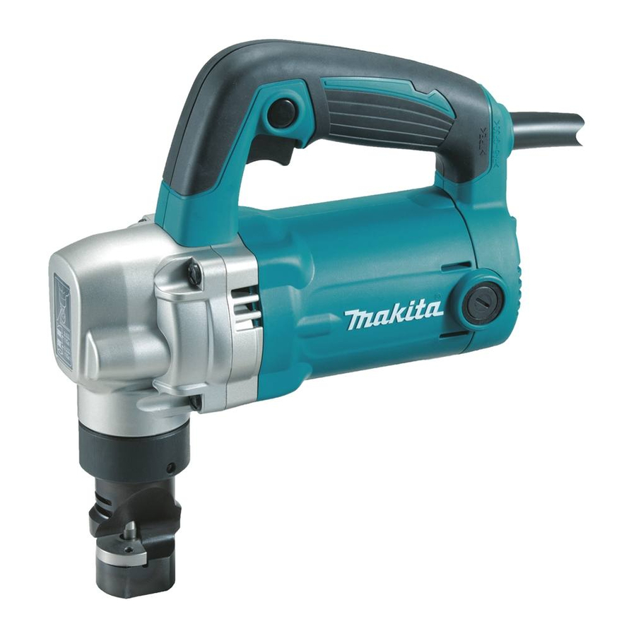
Makita JN3201 Technical Information
Nibbler 3.2mm
Hide thumbs
Also See for JN3201:
- Instruction manual (44 pages) ,
- Instruction manual (9 pages) ,
- Instruction manual (9 pages)
Advertisement
Quick Links
Download this manual
See also:
Instruction Manual
T
ECHNICAL INFORMATION
Model No.
Description
C
ONCEPT AND MAIN APPLICATIONS
Model JN3201 Nibbler is the aesthetic change model of current model JN3200
by using Motor housing of Angle grinder GA5010 series and Rubberized soft grip.
Its Blade section is the same as Nibbler JN3200.
Addition to the above, it has the following advantages.
• 710W continuous rating input
• Low noise level at 81 dB(A)
S
pecification
Voltage (V)
110
120
220
230
240
No load speed: min.
Max cutting capacities:
mm (Ga)
Minimum cutting radius: mm (")
Power supply cord: m (ft)
Weight according to EPTA-Procedure 01/2003
* with Punch and Die
S
tandard equipment
Punch .................................................. 1
Die ....................................................... 1
Wrench 50 .......................................... 1
Hex wrench ........................................ 1
Washer ............................................... 2
Plastic carrying case .......................... 1 (for some country only)
Note: The standard equipment for the tool shown above may vary by country.
O
ptional accessories
Punch
Die
JN3201
Nibbler 3.2mm (10Ga)
Current (A)
Cycle (Hz)
6.8
50/60
6.2
50/60
3.4
50/60
3.3
50/60
3.1
50/60
¹=spm (strokes per minute)
ˉ
Steel with tensile strength
up to 400N/mm²
Steel with tensile strength
up to 600N/mm²
Steel with tensile strength
up to 800N/mm²
Aluminum with tensile
strength up to 200N/mm²
*
: kg (lbs)
Continuous Rating (W)
Input
Output
710
400
---
400
710
400
710
400
710
400
1,300
3.2 (10)
2.5 (13)
1.0 (20)
3.5 (10)
Outer edge: 128 (5-1/16),
Inner edge : 120 (4-3/4)
European countries: 4.0 (13.1),
Australia, New Zealand: 2.0 (6.6)
Other countries: 2.5 (8.2)
3.4 (7.4)
PRODUCT
P 1/ 9
L
H
W
Dimensions: mm (")
Length (L)
225 (8-7/8)
Width (W)
90 (3-1/2)
Height (H)
254 (10)
Max. Output (W)
600
600
700
700
700
Advertisement

Related Manuals for Makita JN3201


Summary of Contents for Makita JN3201
- Page 1 Nibbler 3.2mm (10Ga) ONCEPT AND MAIN APPLICATIONS Model JN3201 Nibbler is the aesthetic change model of current model JN3200 by using Motor housing of Angle grinder GA5010 series and Rubberized soft grip. Its Blade section is the same as Nibbler JN3200.
-
Page 2: Necessary Repairing Tools
781019-5 Wrench 50 (comes with the product) removing / tightening Lock nut [2] LUBRICATION Apply Makita grease FA No.2 to the following portions designated with the black triangle to protect parts and product from unusual abrasion. Item No. Description Portion to lubricate... - Page 3 P 3/ 9 epair [3] DISASSEMBLY/ASSEMBLY [3] -1. Gear section (cont.) DISASSEMBLING (2) Disassemble the Gears and Punch holder assembly as drawn in Fig. 3. Fig. 3 1. Remove Gear complete 15-46. Note: Be careful not to lose Flat washer 8. 2.
- Page 4 P 4/ 9 epair [3] DISASSEMBLY/ASSEMBLY [3] -1. Gear section (cont.) ASSEMBLING (1) Assemble Spur gear 44 and Crank section as drawn in Fig. 4. Fig. 4 2. Put Super gear 44 and Crank section onto 1R034. 1. Set Woodruff key 4 to Crank shaft. Then, press down the gear with 1R031 until it stops.
- Page 5 P 5/ 9 epair [3] DISASSEMBLY/ASSEMBLY [3] -2. Armature DISASSEMBLING Disassemble Handle set from Motor housing complete as drawn in Fig. 4. Note: Gear housing cover complete, which holds Armature assembly in Motor housing, is fixed to Motor housing complete with Handle set. It is necessary to remove Handle set from Motor housing complete to remove Gear housing cover complete and Gear housing complete.
- Page 6 P 6/ 9 epair [3] DISASSEMBLY/ASSEMBLY [3] -3. Die, Punch DISASSEMBLING (1) Remove Lock nut from Gear housing complete with Wrench 50 as drawn to left in Fig. 2. (2) Remove Dice and Punch as drawn in Fig. 5. Fig. 5 1.
-
Page 7: Circuit Diagram
P 7/ 9 ircuit diagram Fig. D-1 High Voltage with Radio interference suppression Power supply cord Black lead wire is used Noise suppressor for some countries Switch White lead wire is used for some countries. Terminal Line filters block Color index of lead wires' sheath Black Field Blue... - Page 8 P 8/ 9 ircuit diagram Fig. D-1A Low Voltage with Radio interference suppression Power supply cord Noise suppressor Black lead wire is used for some countries Switch White lead wire is used for some countries. Connector 2-SD Color index of lead wires' sheath Black Field Blue...
- Page 9 P 9/ 9 ircuit diagram Fig. D-1B Countries where Radio interference suppression is not required Power supply cord Black lead wire is used for some countries Switch White lead wire is used Terminal block for some countries. Insulated splice Field Color index of lead wires' sheath Black Blue...
Need help?
Do you have a question about the JN3201 and is the answer not in the manual?
Questions and answers