Table of Contents
Advertisement
Quick Links
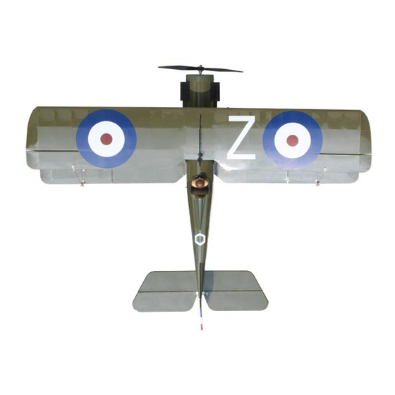
S.E.5a
Important Information:
Please inspect the plane before beginning to assemble to make sure you are happy with it. After
assembly has begun you cannot return the kit. If you find a problem before beginning to assemble the
plane you must contact us, please do not return it to the dealer. Due to temperature changes the plane
may develop some wrinkles in the covering that you will need to remove with an iron. Be sure to seal
the edges down first so that you do not cause the covering to shrink and leave exposed areas of wood.
The model is built light to ensure good flight characteristics. With the power available from the new
breed of engines, it is necessary to use throttle management in order not to overstress the airframe.
You must maintain good tight control linkage with no slop, good servos with plenty of power, and good
servo arms to protect against flutter. Sloppy linkage and over speeding the plane will cause flutter
which is not covered in the warranty. Lanier R/C is proud of the care and attention that goes into the
manufacture of parts for its model kits. The company warrants that for a period of 90 days, it will
replace, at the buyers request, any parts or material shown to the company's satisfaction to have been
defective in workmanship or material at the time of purchase. No other warranty of any kind, expressed
or implied, is made with respect to the merchandise sold by the company. The buyer acknowledges
and understands that he is purchasing only a component kit from which the buyer will himself construct
a finished flying model airplane. The company is neither the manufacturer of such a flying model air-
plane, nor a seller of it. The buyer hereby assumes the risk and all liability for personal or property
damage or injury arising out of the buyers use of the components or the finished flying model airplane,
whenever any such damage or injury shall occur. Any action brought forth against the company, based
on the breach of the contract of sale to the buyer, or on any alleged warranty there under, must be
brought within 1year of the date of such sale, or there after be barred. This one year limitation is
imposed by agreement of the parties as permitted by the laws of the state of Georgia.
Lanier R/C, INC. P.O. Box 458 Oakwood, Ga. 30566 PH 770 532 6401
© copyright 2006 Lanier R/C
Advertisement
Table of Contents

Related Manuals for Lanier R/C S.E.5A


Summary of Contents for Lanier R/C S.E.5A
- Page 1 Sloppy linkage and over speeding the plane will cause flutter which is not covered in the warranty. Lanier R/C is proud of the care and attention that goes into the manufacture of parts for its model kits. The company warrants that for a period of 90 days, it will replace, at the buyers request, any parts or material shown to the company’s satisfaction to have been...
- Page 2 USING THIS INSTRUCTION MANUAL COVERING Before you begin assembling your S.E.5a ARF, take some The S.E.5a ARF is covered in a polyester film chosen for time to read through this entire instruction book. It is its beauty, toughness, and ease of application and repair.
- Page 3 ITEMS NEEDED TO COMPLETE THIS AIRCRAFT Caution: 4 CHANNEL RADIO WITH 4 MICRO SER- VOS. (WE USED 4 CHANNEL FUTABA RADIO WITH S3110 SERVOS AND FUTABA RECEIVER ) Before starting, carefully go 6” SERVO “Y” HARNESS over all high stress areas 12”...
-
Page 4: Aileron Control Horns
Aileron Control Horns Gather the following items: Install the two control horns on the top wing ailerons on the bottom side facing the rear. (6) Small Control Horns (2) Wing (2) EZ Connectors With Hardware (2) Swivel Keeper Installing Ailerons Collect the following parts: (2) Wings (4) Ailerons ( Left &... -
Page 5: Aileron Pushrods
Aileron Pushrods Locate the two aileron servo spacers. Gather the following items: (2)12" Extension wires (1) Bottom Wing (2) Servos (1) Electrical tape (2) Servo spacers Lay the spacer over the cutout for the aileron servo and mark around the outside edge. Carefully remove the covering inside your marks and glue the spacer plate in place. -
Page 6: Main Landing Gear
Main Landing Gear COLLECT THE FOLLOWING PARTS: (1) Fuselage (1) Main Landing gear (4) #2 x 3/8” screws (2) Main Wheels (2) nylon wheel retainers (2) landing gear straps Fit the gear into the slot on the bottom of the fuselage. - Page 7 Installing Stabilizer Mount the bottom wing to the fuselage using the two #4 x 3/4” bolts. COLLECT THE FOLLOWING PARTS: (1) Fuselage (1) Stabilizer (1) Bottom wing (2) #4 x 3/4” screws Slide the stab into the fuselage and align the center marks on both sides of the fuselage.
-
Page 8: Elevator Installation
When stab is properly aligned, make a mark along side the fuselage on the stab top and bottom, left side and right side. Locate the pre-drilled control hole holes in the right side elevator. . Place glue on the control horn pins and insert Carefully cut the covering 1/8”... -
Page 9: Fin & Rudder Installation
Fin & Rudder Installation Deflect the elevator to it full travel (about 1”) and glue the hinges in place using thin CA Collect the following parts: Turn the plane over and repeat for the bottom (1) Fuselage With Stabilizer side. (2) Fin &... - Page 10 Remove the covering by cutting 1/8” inside the line you marked making sure not to cut into the wood. Fit the hinges into placed on the fin and make sure the rudder is tight against the fin. Deflect Glue the fin into the fuselage using epoxy. the rudder to one side about 1-1/2”...
-
Page 11: Pushrod Installation
Pushrod Installation Radio Installation Collect the following parts: Collect the following parts: (2) Nylon swivel keepers (1) Fuselage (2) 20” Long Pushrod Wire (2) Micro Servos with Hardware (Not Included) (1) Micro Receiver (Not Included) (1) Servo “Y” Harness (Not Included) (2) Mini- Pushrod Connectors Insert the pushrod into the tube in the fuse- lage. -
Page 12: Top Wing Installation
Top Wing Installation Collect the following parts: (2) Cabane struts (2) N- struts (16) #2 x 3/8” screws Bolt the bottom wing in place with the landing gear struts under the wing bolts. N-Struts Set the top wing in place on the cabane struts Cabane Struts and install the four screws. - Page 13 Locate the 1/32” x 7” aileron pushrod and make a 90 degree bend 1/4” long in one end. Fit it into the outer hole on the top aileron con- We used the Ultra fly A30-29 brushless motor trol horn and retain with the swivel keeper. which comes with the gear box and prop adapter.
- Page 14 Locate the four plastic nuts on the inside of the fuselage on both side. Take a straight pin We flew the S.E.5a ARF with a Ultrafly brush- and bend a 90 degree angle on one end and less motor A/30/29 with 3.89 gear ratio use it to punch the holes through from the with a 9 x 4.7 Slo-Flyer APC prop...
-
Page 15: Decal Locations
Slip the cowl over the nose of the plane with the paper strips on the outside of the cowl. Transfer the holes to the cowl. Screw the cowl in place with four #2 x 3/8” screws. Glue the headrest to the top of the turtledeck and use masking tape to hold in place till the glue dries. -
Page 16: Control Setup
Balancing Balance the S.E.5a at 1” back from the leading edge of the bottom wing Control Set Up Turn on your transmitter and plug in the receiver battery. Center all the control surfaces (rudder, elevator & aileron). If required by your speed control this is the time to program it for your use.