
Subscribe to Our Youtube Channel
Related Manuals for JUKI MB-1800


Summary of Contents for JUKI MB-1800
- Page 1 Dry-head Type, High-speed, Computer-controlled, Single Thread, Chainstich Button Sewing Machine (with Automatic Thread Trimmer and Knot-tying Mechanism) MB-1800 MB-1800A ENGINEER’S MANUAL 29345105 No.00...
- Page 2 PREFACE This Engineer’s Manual is written for the technical personnel who are responsible for the service and maintenance of the machine. The Instruction Manual for these machines intended for the maintenance personnel and operators at an apparel factory contains operating instructions in detail. And this manual describes “Standard Adjustment”, “Adjustment Procedures”, “Results of Improper Adjutment”, and other important information which are not covered by the Instruction Manual.
-
Page 3: Table Of Contents
14. CAUSE OF TROUBLES AND THE CORRECTIVE MEASURES ............39 (1) Thread trimming troubles and the corrective measures ..................39 (2) Cause of troubles and the corrective measures for MB-1800 ................40 15. CIRCUIT BOARD DIAGRAM ........................ 41 (1) MAIN circuit board ..............................41 (2) PWR circuit board .............................. -
Page 4: Specifications
1. SPECIFICATIONS 1) Sewing area : X (lateral) direction 10 mm Y (longitudinal) direction 6.5 mm (0.2 mm pitch) 2) Max. sewing speed : 1,800 rpm 3) Feed motion of button clamp : Intermittent feed (2-shaft drive by stepping motor) 4) Needle bar stroke : 48.6 mm 5) Needle :... -
Page 5: Name Of Each Component
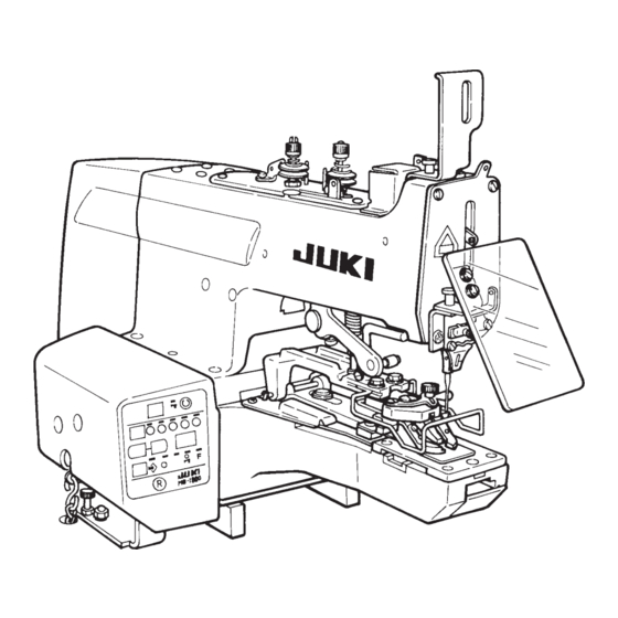
2. NAME OF EACH COMPONENT (1) Name of the main unit • Machine head • Thread stand • Electrical components • Operation panel • Button tray • Power switch • Starting pedal − −... -
Page 6: Operation Of The Sewing Machine
3. OPERATION OF THE SEWING MACHINE (1) Names of the operation panel switches 1 Set ready switch This switch is used when making the sewing machine from setting status to sewing possible status. 2 Button clamp lifting switch This switch performs up/down of the button clamp. -
Page 7: Pattern Table
(2) Pattern table Three same sewing sizes and numbers of stitches for each stitch shape have been stored in pattern Nos. 1 to 51 at the time of delivery. By selecting sewing size and number of stitches from the table below, the stitch shape can be changed to the three different kinds of patterns of the same stitch shape and be stored in memory. -
Page 8: How To Operate And Use The Memory Switch (User Level)
(3) How to operate and use the memory switch (User level) 1) The speed up to 3rd stitch can be set so that the sewing speed at the start of sewing is controlled and the stitch is stabilized. 2) Effective/ineffective of the knot-tying functon can be selected. 3) Operating/non operating of the wiper can be selected. -
Page 9: Standard Adjustment
4. STANDARD ADJUSTMENT Standard Adjustment (1) Height of the needle bar The upper engraved line of the two engraved lines for TQx1 and TQx7 should be aligned with the bottom of the lower bushing when the needle bar is at its lowest position. For TQx1 For TQx1 Lower... - Page 10 Adjustment Procedures Results of Improper Adjustment 1) Slightly loosen knob 1 and turn cover 2 in the direction ™ If the needle bar is too high, skipped of the arrow and you will find hand pulley 3. stitches will be produced. 2) Turn the hand pulley by hand, loosen setscrew 4 in the If the needle bar is too low, the needle needle bar thread-take up lever and adjust so that the...
-
Page 11: Timing The Travel Of The Yoke Slide
Standard Adjustment (3) Timing the travel of the yoke slide 1) Crosswise travel timing of the yoke slide Yoke slide The height of the descending needle bar is 53 to 58 mm when the yoke slide advances and begins to travel from the right to the left (TQx7). - Page 12 Adjustment Procedures Results of Improper Adjustment ™ If the triangle loop positioning finger ™ For adjusting the timing of the travel of the yoke slide, cam begins to travel too late, thread align the engraved marks of the loop positioning finger breakage, thread remaining, baloon cam and the triangle loop positionig finger cam with the stitch, and insufficient tightness of...
-
Page 13: Lift And Pressure Of The Button Clamp
Standard Adjustment (5) Lift and pressure of the button clamp 1) Lift of the button clamp A Standard : 12 mm Max. : 9 mm 2) Pressure of the button clamp Adjust the position of the pressure adjusting nut to 4 to 5 mm. - Page 14 Adjustment Procedures Results of Improper Adjustment ™ Increasing the lifting amount of the 1) The knife moves in accordance with the lifting of the button clamp. Therefore, the length of the remaining thread on button clamp will increase the length the wrong side of a fabric depends upon the height of the of the remaining thread.
-
Page 15: Adjusting The Position Of The Moving Knife
Standard Adjustment (2) Adjusting the position of the moving knife Adjust the position so that the distance between the thread trimming connecting plat (front) and the edge of the slot in the throat plate should be 12 to 13 mm when the button clamp is at its highest position. (3) Adjusting the height of the thread separating claw of the moving knife Make adjustment so that the clearance between the thread separating claw 1 and the looper 2 should become 0.5 to 0.7 mm. - Page 16 Adjustment Procedures Results of Improper Adjustment 1) Remove cover 1 with setscrew 2. ™ If this dimension is excessively large, 2) In order to place thread trimming connecting plate A 9 to the thread trimming timing is delayed the most advanced position, lift the presser lifter lever to and the remaining thread on the wrong such an extent that roller 4 and hook 5 of presser lifter side of cloth is lengthened.
-
Page 17: Procedures In Disassembling And Assembling
6. PROCEDURES IN DISASSEMBLING AND ASSEMBLING Procedures in disassembling and assembling (1) Name of each component Needle bar upper bushing Rocking rod fulcrum shaft Needle bar clamp Crank rod hinge screw Needle bar lower bushing Loop Yoke slide positioning Triangle loop positioning finger cam finger cam Needle bearing Feed needle bearing... - Page 18 Cautions in disassembling Cautions in assembling − −...
-
Page 19: Disassembling The Circuit Board
Procedures in disassembling and assembling (2) Disassembling the circuit board 1) Cover components Control box cover Side cover 2) Circuit board components MAIN circuit board POWER circuit board MAIN circuit board Setscrew 1 Setscrew 3 Circuit board installing plate Collar Setscrew 3 POWER circuit board Setscrew 2... - Page 20 Cautions in disassembling Cautions in assembling Disassembling and assembling of the circuit board Assembling Disassembling 1) Assemble in the order of MAIN circuit 1) Remove the control box cover and the side cover. board, collar, circuit board installing Remove all connectors connected to the circuit board. plate, collar and POWER circuit board.
-
Page 21: Disassembling The Machine Arm And Bed
Procedures in disassembling and assembling (3) Disassembling the machine arm and bed 1) Bed components • Rubber base • Crank rod Stud Base cover Rubber base • Starting spring • Throat plate Starting lever spring Setscrew 2) Arm components Bed connecting bolt −... - Page 22 Cautions in disassembling Cautions in assembling Disassembling and assembling the machine arm and bed Assembling Disassembling 1) Hold the machine arm and place it on the surface of the machine bed so that (Note) When disassembling the machine arm and bed, the thread trimming connecting plate remove the whole set of the circuit board.
-
Page 23: Disassembling The Looper Shaft
Procedures in disassembling and assembling (4) Disassembling the looper shaft 1) Disassembling Looper support screw Loop positioning finger cam setscrew Looper shaft Oil seal Needle bearing Needle bearing Thrust collar Thrust bearing Thrust collar Screw gear Thrust bearing Loop positioning finger cam Looper installing shaft Triangle loop positioning finger cam 2) Screw gear components... - Page 24 Cautions in disassembling Cautions in assembling Disassembling and assembling the looper shaft Assembling Disassembling 1) Fully apply grease to the inside of the 1) Disassemble the machine arm and bed. Refer to the item bushing. “Disassembling the machine arm and bed” P.18. (It is not necessary when filling grease with grease gun or the like from the 2) Remove the throat plate and remove the components...
-
Page 25: Disassembling The Driving Shaft
Procedures in disassembling and assembling (5) Disassembling the driving shaft • Disassembling 1) For the removing procedure of the circuit board, base cover and crank rod, see P.18. 2) Bushing and stator setscrew Driving shaft bushing, left Crank rod Screw gear Motor cover Thrust bearing Ball bearing... - Page 26 Cautions in disassembling Cautions in assembling Disassembling and assembling of the driving shaft Assembling (Note) Do not disassemble the driving shaft except 1) Install the screw gear. when it has broken since since the motor is (Clearance : 4 to 4.2 mm) built in.
- Page 27 Procedures in disassembling and assembling (5) Disassembling the driving shaft • Assembling and adjusting procedure of the servo-motor 15) Stator setscrew 16) Cord outlet 17) Operation panel Cord outlet Stator setscrew 18) Panel display 20) Fixing stator 21) Encoder Encoder installing screw 23) Encoder setscrew 24) Encoder “0”...
- Page 28 Cautions in disassembling Cautions in assembling 12) Raise the sewing machine and install the circuit board. Refer to the item “Circuit board”. P.16. 13) Connect all connectors with the side cover removedand install the control box cover. 14) Tilt the sewing machine. Turn the hand pulley to bring the needle bar to its lowest position.
-
Page 29: Adjustment Of The Sensors
7. ADJUSTMENT OF THE SENSORS Standard Adjustment (1) Adjusting the starting sensor Starting lever Thrust collar Sensor slit Starting sensor Setscrew Starting sensor plate setscrew Starting sensor Presser lifter sensor Starting lever Starting lever bracket setscrew Sensor slit Starting lever stopper Starting lever bracket (2) Adjusting the presser lifter sensor... - Page 30 Adjustment Procedures Results of Improper Adjustment (1) Adjusting the starting sensor 1) Loosen the starting sensor plate setscrews. 2) In the state that the starting lever comes in contact with the starting lever stopper, adjust so that the sensor slit does not pass the sensor and is as high as the sensor, and fix the starting sensor plate setscrews.
-
Page 31: Adjusting The Feed Origin Sensor
Standard Adjustment (3) Adjusting the feed origin sensor Sensor slits are in the same direction. Sensor slit Setscrew Origin sensor Origin sensor installing plate setscrew Origin Origin sensor, sensor, left LD2 right LD3 Origin sensor installing plate setscrew (4) Adjusting the presser lifter stopper 10 mm −... - Page 32 Adjustment Procedures Results of Improper Adjustment (3) Adjusting the feed origin sensor 1) Remove the hinge screw attached to the machine arm, enter the sensors in the hole of the feed plate, and fix them with the screw hole in the bed. 2) Tilt the sewing machine.
-
Page 33: How To Operate And Use The Memory Switch (Service Level)
8. HOW TO OPERATE AND USE THE MEMORY SWITCH (SERVICE LEVEL) The operation to adapt the various specifications, more stabilized stitching, etc. can be performed by selecting or changing the various operations, various timings, time, etc. of the sewing machine. 1) Pressing –... -
Page 34: Memory Switch Function Table
(1) Memory switch function table Memory Setting Unit Setting level Setting range Setting item Contents of setting initial value switch No. Soft start speed setting Speed of 1st stitch at the sewing start can be limited. x100 [rpm] User 4 to 18 (1st stitch at the sewing start) Speed of 2nd stitch at the sewing start can be limited. - Page 35 Memory Setting Setting range Unit Setting item Contents of setting Setting level initial value switch No. Thread trimming operation setting (1) Thread trimming (presser lifting) solenoid ON timing angle (upper dead point of one stitch before the last stitch is regarded as 0˚) x10 [deg] Service 0 to 40...
-
Page 36: How To Operate And Use The Input Check Mode Function
9. HOW TO OPERATE AND USE THE INPUT CHECK MODE FUNCTION Troubles, defects, etc. of the printed circuit boards and elements can be checked by displaying the input state of the various sensors and switches. 1) Pressing Set ready switch and Reset switch, turn ON the power. (“Function No. 1” is displayed.) Display section (Flashing display) 2) When Item selection switch is pressed down, the state of input assigned to “Function No. -
Page 37: Input Check Correspondence Table
(1) INPUT CHECK CORRESPONDENCE TABLE Function Left-hand side of display section Right-hand side of display section (10th digit) (1st digit) Origin detection sensor (Left stepping motor) Origin detection sensor (Right stepping motor) : ON, : OFF [CN20-2] : ON, : OFF [CN21-2] Presser lifting detection sensor Presser lowering detection sensor : ON,... -
Page 38: How To Operate And Use The All Clear Function
10. HOW TO OPERATE AND USE THE ALL CLEAR FUNCTION All of the data (size, number of stitches, etc.) of each pattern No. and the set value of the memory switch can be cleared and returned to the set value at the time of delivery. However, when this operation is performed, all the up-to-date data are deleted. -
Page 39: Parts To Be Greasesd
11. PARTS TO BE GREASESD Apply or fill up grease to the following parts. − −... -
Page 40: Error List
12. ERROR LIST Error LED located on the left side of the reset switch flashes on and off or lights up when an error occurs. When the LED lights up, the setting state will be made by pressing the reset switch and the error will be released. -
Page 41: Change-Over Of The Power Source Voltage
13. CHANGE-OVER OF THE POWER SOURCE VOLTAGE This sewing machine has been connected to the power source of 200V to 240V in the state of delivery from the factory. When using the machine with the power source of 100V to 120V, perform the work of change-over of voltage in the order of the procedures below. -
Page 42: Cause Of Troubles And The Corrective Measures
14. CAUSE OF TROUBLES AND THE CORRECTIVE MEASURES (1) Thread trimming troubles and the corrective measures Troubles Causes Corrective measures 1. Thread is not trimmed. The thread separating claw of the Adjust the position of the moving knife. moving knife fails to separate the Refer to the item “5. -
Page 43: Cause Of Troubles And The Corrective Measures For Mb-1800
(2) Cause of troubles and the corrective measures for MB-1800 Troubles Causes Corrective measures 1. The machine fails to sew at Length of remaining thread is too Adjust the thread adjusting thread the start of sewing. short. guide. Speed is fast. -
Page 44: Circuit Board Diagram
15. CIRCUIT BOARD DIAGRAM (1) MAIN circuit board − −... -
Page 45: Pwr Circuit Board
(2) PWR circuit board (3) PANEL circuit board − −... -
Page 46: Block Diagram 1/2
16. BLOCK DIAGRAM 1/2 − −... - Page 47 Block diagram 2/2 Part No. Name of part Circuit diagram M8601630AA0 MAIN circuit board A asm. M86046300A0 PWR circuit board asm. M86026300A0 PANEL circuit board asm. M85026300A0 Temperature sensor cord asm. Sensor connection diagram M85196300A0 Thread tension relay cord asm. Solenoid circuit diagram M85236000A0 Input change-over cord asm.
-
Page 48: Connection Diagram And Circuit Diagram
17. CONNECTION DIAGRAM AND CIRCUIT DIAGRAM (1) Power connection diagram − −... -
Page 49: Sensor Connection Diagram
(2) Sensor connection diagram − −... -
Page 50: Motor Circuit Diagram
(3) Motor circuit diagram CN16 ORANGE L1-A WHITE FEED 1 STEPPING +24V MOTOR BLUE L1-A L1-B BLACK +24V YELLOW L1-B CN17 ORANGE L2-A WHITE FEED 2 STEPPING +24V MOTOR BLUE L2-A L2-B BLACK +24V YELLOW L2-B CN18 BLACK SERVO-MOTOR WHITE PGND −... -
Page 51: Encoder Circuit Diagram
(4) Encoder circuit diagram CN19 SERVO ENCODER BROWN TS5207N530 BROWN/BLACK GRAY GRAY/BLACK WHITE WHITE/BLACK GREEN GREEN/BLACK BLUE BLUE/BLACK YELLOW YELLOW/BLACK BLACK BLACK SHIELD (5) Solenoid circuit diagram CN15 WHITE +24V WHITE PRESSER PRESSER LIFTER LIFTER CN14 WHITE +24V WHITE KNOT- TYING KNOT- TYING CN13... -
Page 52: Drawing Of The Table
18. DRAWING OF THE TABLE 3. Painting inside of cut portion is not necessary. 2. Do not peel the protection sheet from the surface of table. (Note) 1. Tolerance of hole without indication is ± 0.7 and that of others ± 1.0. −... - Page 53 * The description covered in this engineer’s manual is subject to change for improvement of the TELEX : J22967 commodity without notice. Copyright C 2000 JUKI CORPORATION. All rights reserved throughout the world. 00 · 04 Printed in Japan (E)
Need help?
Do you have a question about the MB-1800 and is the answer not in the manual?
Questions and answers