Table of Contents
Advertisement
Quick Links
Features :
- Best 3D Performance
- Precision ECCPM 120° Metal Swashplate
- Easy Maintenance
- 80% Preassembled
- Low Parts Count
- Wear Resistant Parts
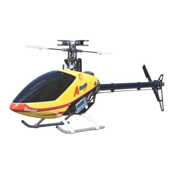
Equipped with extra Strong Frames, Aluminum Rotor Head, Aluminum Tail Rotor and a
Metal Swashplate the Atom 500 not only looks great but is long lasting.
As we continue to improve our products; this manual may not reflect all recent product amendments.
For more information, please refer to www.compassmodel.com
Fly at your own risk !
Copyright Compass Model 2008
Assembly Manual
Version 2.0
Created : 10/26/2009
Advertisement
Table of Contents

Subscribe to Our Youtube Channel
Related Manuals for Compass Model Atom 500


Summary of Contents for Compass Model Atom 500
- Page 1 - Wear Resistant Parts Equipped with extra Strong Frames, Aluminum Rotor Head, Aluminum Tail Rotor and a Metal Swashplate the Atom 500 not only looks great but is long lasting. Copyright Compass Model 2008 As we continue to improve our products; this manual may not reflect all recent product amendments.
-
Page 2: Ama Information
Model Ltd. assumes no liability for damage that could occur from the assembly and/or use/misuse of this product. Although the Atom 500 is powered by a quiet, smooth-running electric motor, it should be assembled and operated with the same care as its larger glow engine counterparts. -
Page 3: Guidelines For Safe R/C Helicopter Flight
Great care has been taken in filling the bags with the correct quantity of parts and hardware for each section. However, occasional mistakes happen. In the event that you find a parts shortage or are in need of technical assistance, please contact your local Compass Model parts dealer. - Page 4 In The Box This model is packed according to assembling steps. Do not open all the bags at one time. Open only one bag for each step of assemply when building. Atom 500 Step 1 Step 2 Step 3 Long Items...
-
Page 5: Landing Gear
Servo The Servo installation is done without the supplied Servo Rubbers. M2.5x16 Self Tapping Bolt X 4 M2.5x8 Self-Tapping Bolt Mini Servo M2.5x10 Self Tapping Bolt X 4 2.5mm Washer M2.5x8 Self Tapping Bolt X 8 The Swashplate Servos are installed in between the 2 frames. - Page 6 Boom & Tail Rotor Crimping Belt damages the Tensile Cords and will result in premature failure. M3 Washer x2 M3 Nylon Lock Nut x6 Be careful not to over tighten the Bolts when attaching the Tail Rotor Blades. The Tail Blades should be M2.5x6 Cap Head Bolt x2 able to move with a slight amount of resistance within the Tail Blade...
- Page 7 Main Gear Lift the Main Shaft Collar upwards and M2.5 Nylon Lock Nut x1 secure to the Main Shaft by slightly tighten the Lock Screw. It is necessary Main Shaft to align the Lock Screw through the M2.5x10 Cap Head Bolt x1 hole in the side of the Main Frame.
- Page 8 Rotor,Washout & Swashplate M2.5 x8 Self Tapping Bolt X 4 M3x3 Set Screw x8 In this step, push the Flybar trough the Flybar Collar, Flybar Holder and the Flybar Control Arms using the 3x3mm 2.5mm Nut x1 M3x3 set screws to fix the Arms and Collars Set Screw onto the Flybar, care that both sides of the Flybar are of equal length.
- Page 9 Equipment illustration Aileron Pitch Elevator Rudder Receiver ES C Linkage The following Linkage lengths indications are basic values. PLEASE BE AWARE THAT THEY COULD VARY depend on used Servos and Arms. Some fine adjustments are still needed in following setup steps. Please cut away 4.5mm from each Ball Link.
- Page 10 Stainless Balls For Sport Flying For 3D Flying Compass Model Ball Links are build up on Do not apply plier to resize Ball Links. Pliers could the tight side this allows you to adjust them cause hidden damage to Ball Links and result in to your personal needs.
- Page 11 Parallel Make sure that the Flybar Control Arms and Paddles are in line as shown in the diagram. Attention: To do all Basic Setups first UNPLUG ESC from the receiver then use a 4.8V Receiver Battery for the setup. Horizontal Horizontal Turn on the Transmitter, set the Throttle Stick into center position for 0 °...
- Page 12 7° Use this Hole for Tail Link Ball With Rudder Stick in middle position, set the Rudder Servo Arm at 90° to the Tail Control Link. Set the Tail Blades to 7° Pitch. Servo Direction Check Turn the Transmitter on, your position has to be right behind the helicopters Tail. Make sure that the Swashplate Mode is set to CCPM 120°.
-
Page 13: Rotor Direction
Canopy Canopy M2.5x6 Self Tapping Bolt X 2 Use AB Glue Drill a 6.5mm D Hole here Canopy Insert M2.5x6 Self Tapping Bolt Place the Canopy onto the Frames and mark the right position of the Canopy Inserts. Apply AB Glue to fix the Canopy Insert onto the canopy. - Page 14 Team Tips General: The Ball Links on the Atom need to be resized. These Ball Links will NOT break in over time. they will stay tight and will cause unwanted interactions. Step 3 It is very important to resize the Ball Links for smooth travel, especially on the tail; because issues like tail wag, sluggish tail, or inconsistent Piro-rate will occur.
-
Page 15: Parts List
Use the part number to find the ORDER number on the list Only use ORDER number for your parts order Copyright Compass Model 2009 As we continue to improve our products, this part list may not reflect all recent product amendmends. - Page 16 06-8104 06-0106N 80-2516 06-0102 61-3062 91-0025 79-0306 06-0114 97-0715 06-5101 06-0109 60-6124 80-0322S 80-0206 02-0701 06-0108 80-2506 06-0101 79-0408 91-0003 63-61245 82-621003 60-6124 82-4101 06-0512 80-0206S 06-0510 02-0701 06-0511 06-0507 81-0303 06-0504 06-0508 06-0507 60-2562 80-0206S 81-0303 02-0701 81-0303 81-030 06-0505 06-0513 61-2562...
- Page 17 1 set/bag 06-0106N Rotor Hub 06-0106Z Rotor Hub set (Atom 500) 1 set/bag 06-0108 Main Blade Holder Arm 06-0108S Main Blade Holder Arm set (Atom 500) 2 set/bag 06-0109 Delrin Dampner 06-0109 Delrin Dampner (Atom 500) 2 pcs/bag 06-0114 Spindle Shaft...
- Page 18 61-2562 06-0503 82-2540 06 8502 61-2052 06-0518 82-2540 61-2052 80-0205 80-2510 80-0206 02-0701 61-2562 06-0607 06-0520 06 0410S 06-8421 80 0206 80-2510 06-0608 9 1 00 25 80-2518 06-4502 80-2508 06-4603 60-10153 62-101412 06 8602 06-0603 6 -101 06-0605...
- Page 19 Main Shaft (Ø 8mm) 06-0607 Main Shaft (Atom 500 Ø 8mm) 1 pcs/bag 06-0608 Main Shaft Lock Clamp (Ø 8mm) 06-0608S Main Shaft Lock Clamp set (Atom 500 Ø 8mm) 1 set/bag 06-4502 06-4502 Main Pulley Main Pulley (Atom 500) 1 pcs/bag...
- Page 20 06-8203 07 0818 82 3 - 504 61 3084 06 0828 9 0003 61 3084 06 0843 80 0314 06 0905 60 8165 06 0606 02 0 805 81 0316 80 0340 06 0822 06 8203 06 0812 06 0830R 06 4308 06 4309 06 0822...
- Page 21 06-0812 Canopy Standoff 06-0812 Canopy Standoff set (Atom 500) 2 pcs/bag 06-0818 Landing Gear Skid 06-0818S Landing Gear Skids w. Caps (Atom 500) 2 pcs/bag 06-0822 06-0822 Cross Member Cross Member set (Atom 500) 2 pcs/bag 06-0827 Landing Gear Strut...
- Page 22 06 0216 80 2512 06 0210A 06-5210 80 2508 82 2507 80 0206s 63 4094 02 0701 80 0208 06 0210B 60 4094 06 0209 81 0305 06-5206 06 0205 06 0204 61 6103 06 0222 06 0206 61 6103 06 0207 98 1263 61 4104...
- Page 23 02-0701 02-0701 Stainless Link Ball Stainless Link Balls 10 pcs/bag 06-0204 Tail Pitch Plate 06-0204S Tail Pitch Plate w. Pin (Atom 500) 1 set/bag 06-0205 Tail Blade Link 06-0205S Tail Blade Links w, Pin (Atom 500) 2 set/bag 06-0206Z 06-0206 Tail Pitch Slider Tail Pitch Slider w.
- Page 24 F 06 0430 06-8202 (F 06 0430T) 06-0823AB 91 003 80-0325 8 -32 06-0826 06-0817 02-0818 0- 455 0 6 0 7 07 F U ( 0 6 0 7 0 7 JR ) 02 0853 V BT 2 7 0 06 0851 06-0852 40 2010...
- Page 25 06-0852 FG Canopy White (Atom) 06-0852W FG Canopy White (Atom) 1 set/bag 06-8202 Tail Gear Box set 06-8202 Tail Gear Box set Complete (Atom 500) 1 set/bag 06-0707FU Servo Arm (FUTABA) 06-0707FU Servo Arm set (FUTABA) 1 set/bag 06-0707JR Servo Arm (JR)
- Page 26 COMPASS MODEL (HK) LIMITED www.compassmodel.com...
Need help?
Do you have a question about the Atom 500 and is the answer not in the manual?
Questions and answers