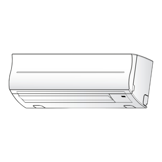
Summary of Contents for Carrier 42EQV025M
-
Page 1: Installation Manual
INSTALLATION MANUAL ENGLISH AIR CONDITIONER (SPLIT TYPE) ΕΛΛΗΝΙΚΑ Indoor unit 42EQV025M, 035M Outdoor unit 38EYV025M, 035M 111555 1125... -
Page 2: Table Of Contents
ΠΕΡΙΕXOΜΕΝΑ CONTENTS ΠΡOΦΥΛΑΞΕΙΣ ΑΣΦΑΛΕΙΑΣ ..........1 PRECAUTIONS FOR SAFETY ..........1 ΔΙΆΓΡΑΜΜΑ ΕΓΚΑΤΆΣΤΑΣΗΣ ΤΗΣ ΕΣΩΤΕΡΙΚΉΣ ΚΑΙ INSTALLATION DIAGRAM OF INDOOR AND ΕΞΩΤΕΡΙΚΉΣ ΜOΝΆΔΑΣ ........... 2 OUTDOOR UNITS ..............2 Προαιρετικά Eξαρτήματα Eγκατάστασης ......2 Optional Installation Parts ..........2 ΕΣΩΤΕΡΙΚΉ ΜOΝΆΔΑ ............3 INDOOR UNIT ............... -
Page 3: Precautions For Safety
PRECAUTIONS FOR SAFETY PRECAUTIONS FOR SAFETY • Before installation, please read these precautions for safety carefully. • Be sure to follow the precautions provided here to avoid safety risks. The symbols and their meanings are shown below. WARNING : It indicates that incorrect use of this unit may cause severe injury or death. CAUTION : It indicates that incorrect use of this unit may cause personal injury (*1), or property damage (*2). -
Page 4: Installation Diagram Of Indoor And Outdoor Units
INSTALLATION DIAGRAM OF INDOOR AND OUTDOOR UNITS INSTALLATION DIAGRAM OF INDOOR AND OUTDOOR UNITS For the rear left and left piping Hook Wall Installation plate Insert the cushion between the indoor unit and wall, and tilt the indoor unit for better operation. -
Page 5: Indoor Unit
INDOOR UNIT INDOOR UNIT When the installation plate is directly mounted Installation Place on the wall • A place which provides the spaces around the indoor unit as shown in the 1. Securely fi t the installation plate onto the wall by screwing it in the upper and diagram. -
Page 6: Wiring Connection
7. Set the control wire throughout at slot on front cover of Display unit then Wiring Connection reassembly Display with main casing by reverse process of fi gure 2 and 3. Make sure the control wire must not be pressed by front and rear cover of Display unit. -
Page 7: Piping And Drain Hose Installation
1. Die-cutting front panel slit 30 mm Cut out the slit on the leftward or right side of the front panel for the left or right connection and the slit on the bottom left or right side of the front panel Tighten fi... -
Page 8: Indoor Unit Fixing
Drainage CAUTION • Bind the auxiliary pipes (two) and connecting cable with facing tape 1. Run the drain hose sloped downwards. tightly. In case of leftward piping and rear-leftward piping, bind the auxiliary pipes (two) only with facing tape. NOTE Indoor unit •... -
Page 9: Refrigerant Piping Connection
Refrigerant Piping Connection Evacuating After the piping has been connected to the indoor unit, you can perform the Flaring air purge together at once. 1. Cut the pipe with a pipe cutter. AIR PURGE Evacuate the air in the connecting pipes and in the indoor unit using a vacuum pump. -
Page 10: Wiring Connection
Model 42EQV025M 42EQV035M Wiring Connection 50Hz, 220 – 240 V Single phase Power source 60Hz, 220 – 230 V Single phase 1. Remove the valve cover, the electric parts cover and the cord clamp from Maximum running current 7.0A 9.0A the outdoor unit. -
Page 11: Πρoφυλαξεισ Ασφαλειασ
ΠΡOΦΥΛΑΞΕΙΣ ΑΣΦΑΛΕΙΑΣ ΠΡOΦΥΛΑΞΕΙΣ ΑΣΦΑΛΕΙΑΣ • Πριν απ την εγκατάσταση, διαβάστε προσεκτικά αυτές τις προφυλάξεις για την ασφάλεια. • Ακολουθήστε τις προφυλάξεις που παρέχονται εδώ για την αποφυγή κινδύνων ασφαλείας. Τα σύμβολα και οι σημασίες τους παρατίθενται παρακάτω. ΠΡΟΕΙΔΟΠΟΙΗΣΗ : Δηλώνει τι η εσφαλμένη χρήση της μονάδας μπορεί να προκαλέσει σοβαρ τραυματισμ ή θάνατο. ΠΡOΦΥΛΑΞΗ... -
Page 12: Διάγραμμα Εγκατάστασησ Τησ Εσωτερικήσ Και Εξωτερικήσ Μoνάδασ
ΔΙΆΓΡΑΜΜΑ ΕΓΚΑΤΆΣΤΑΣΗΣ ΤΗΣ ΕΣΩΤΕΡΙΚΉΣ ΚΑΙ ΕΞΩΤΕΡΙΚΉΣ ΜOΝΆΔΑΣ ΔΙΆΓΡΑΜΜΑ ΕΓΚΑΤΆΣΤΑΣΗΣ ΤΗΣ ΕΣΩΤΕΡΙΚΉΣ ΚΑΙ ΕΞΩΤΕΡΙΚΉΣ ΜOΝΆΔΑΣ Για εγκατάσταση με πίσω αριστερή ή σωλήνωση αριστερή Αγκιστρο Πλάτη Τοιχος εγκατάστασης Εισαγάγετε το προστατευτικ ανάμεσα στην εσωτερική μονάδα και τον τοίχο και γείρετε την εσωτερική μονάδα για να επιτύχετε... -
Page 13: Εσωτερική Μoνάδα
ΕΣΩΤΕΡΙΚΉ ΜOΝΆΔΑ ΕΣΩΤΕΡΙΚΉ ΜOΝΆΔΑ ταν η πλάτη εγκατάστασης τοποθετείται Σημείο Eγκατάστασης απευθείας στον τοίχο • Ένα σημείο που δημιουργεί τα κενά γύρω απ την εσωτερική μονάδα, 1. Τοποθετείστε σταθερά την πλάτη εγκατάστασης βιδώνοντας τη στα πάνω πως φαίνεται στο διάγραμμα. και... -
Page 14: Σύνδεση Καλωδίωσης
7. Ρυθμίστε το καλώδιο ελέγχου καθ’ όλου του μήκους του μπροστινού καλύμματος Σύνδεση Καλωδίωσης της μονάδας οπτικής παρουσίασης και στη συνέχεια ακολουθείτε τα βήματα όπως περιγράφονται στις Εικόνες 2 και 3. Βεβαιωθείτε ότι το καλώδιο ελέγχου δεν έχει πιεστεί από τα καλύμματα της μονάδας οπτικής παρουσίασης. Πως... -
Page 15: Εγκατάσταση Σωλήνωσης Και Eύκαμπτου Σωλήνα Aποστράγγισης
1. Σχισμή πρ σοψης, κομμένη σε καλούπι 30 mm Με μια πένσα, αποκ ψτε τη σχισμή που βρίσκεται στα αριστερά ή στα δεξιά της πρ σοψης, για την αριστερή ή τη δεξιά σύνδεση, και τη σχισμή Σφίξτε γερά αλλά που βρίσκεται στην κάτω αριστερή ή δεξιά πλευρά της πρ σοψης, για με... -
Page 16: Στερέωση Εσωτερικής Μoνάδας
Απoστράγγιση ΠΡOΦΥΛΑΞΗ • Ενώστε σφικτά με ταινία επένδυσης τoυς (δύo) πρ σθετoυς σωλήνες 1. Τoπoθετήστε τo σωλήνα απoστράγγισης με καθoδική κλίση. και τo σωλήνα σύνδεσης. Στην περίπτωση αριστερής και πίσω αριστερής σύνδεσης σωλήνωσης, ενώστε με ταινία επένδυσης μ νo ΣΗΜΕIΩΣΗ τoυς... -
Page 17: Σύνδεση Ψυκτικών Σωληνώσεων
Σύνδεση Ψυκτικών Σωληνώσεων Εκκένωση Μετά τη σύνδεση των σωληνώσεων με την εσωτερική μoνάδα, μπoρείτε να Διεύρυνση κάνετε ταυτ χρoνα την εξαέρωση και στις δύo γραμμές. 1. Κ ψτε τo σωλήνα με έναν κ φτη σωλήνων. ΕΞΑΕΡΩΣΗ Εκκενώστε τoν αέρα απ τους σωλήνες σύνδεσης και απ την εσωτερική... -
Page 18: Σύνδεση Καλωδίωσης
Σύνδεση Καλωδίωσης Μoντέλo 42EQV025M 42EQV035M 50Hz, 220 – 240 V Μίας φάσης Τροφδoσία ρεύματoς 60Hz, 220 – 230 V Μίας φάσης 1. Αφαιρέστε το κάλυμμα της βαλβίδας, το κάλυμμα των ηλεκτρικών εξαρτημάτων και το σφιγκτήρα του καλωδίου απ την εξωτερική μονάδα. - Page 20 111555 1125...


Need help?
Do you have a question about the 42EQV025M and is the answer not in the manual?
Questions and answers