
Related Manuals for Beretta HP 260


Summary of Contents for Beretta HP 260
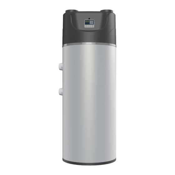
- Page 1 DOMESTIC HOT HEAT PUMP POMPA CIEPŁA WATER CIEPŁA WODA HP 260 UŻYTKOWA INSTALLATION MANUAL INSTRUKCJA INSTALACJI I UŻYTKOWANIA...
- Page 2 BRAND: BERETTA SERIES : HP ACS MODEL: HP 260 ACS HP 260 ACS S HP 260 ACS SC According to: • Electromagnetic Compatibility Directive 2004/108/CE • Low voltage Directive 2006/95/CE • Machinery Directive 2006/42/CE • Directive on the restriction of the use of certain hazardous substances in Electrical and Electronic Equipment 2002/95/CE •...
-
Page 3: Table Of Contents
ENGLISH POLSKI INDEX SPIS TREŚCI 1. INFORMACJE OGÓLNE . . . . . . . . . . . . . . . . . . . . . . . 4 1. -
Page 4: General
ENGLISH POLSKI 1 . GENERAL 1 . INFORMACJE OGÓLNE 1 .1 GENERAL SAFETY DEVICES 1 .1 WARUNKI BEZPIECZEŃSTWA This instructions manual is integral parts of the product. Make Instrukcja obsługi i montażu jest integralną częścią urządze- sure they remain with the appliance, even if it is transferred to nia dlatego musi być... -
Page 5: Identification Unit
ENGLISH POLSKI 1 .3 IDENTIFICATION UNIT 1 .3 OZNACZENIE 1 .3 .1 IDENTIFICATION CE 1 .3 .1 OZNACZENIE CE Pompa ciepła jest urządzeniem zaprojektowanym UWAGA: Important note: The heat pump is a machine designed and i skonstruowanym wyłącznie w celu przygotowania ciepłej built exclusively for the production of hot water for domestic, wody użytkowej. -
Page 6: General Characteristics
- Dodatkowe wężownice do podłączenia instalacji solarnej i/lub ko- - Thermal insulation with injected polyurethane with high thickness. tła gazowego (HP 260 ACS S e SC). - External coating in RAL 7001 grey plastic. - Sonda NTC do kontroli temperatury wody. -
Page 7: Configurations
(Zegar). - Przycisk zdalnego włączania (ON) i wyłączania (OFF) dla grzałki elektrycznej. To adapt at different installation requirements, the HP 260 module is - System podgrzewu przez grzałkę elektryczną przy niskiej tem- available in three versions: peraturze zewnętrznej w automatycznym i ręcznym trybie pracy. -
Page 8: Technical Data
ENGLISH POLSKI 1.8 DANE TECHNICZNE 1.8 TECHNICAL DATA MODEL HP ACS HP ACS S HP ACS SC MODEL Tank capacity litri litr Pojemność zasobnika Surface auxiliary coil Powierzchnia wężownicy 0.6/1.5 Przepływ wody w do- Auxiliary coil water flow 80/60°C 0.6/1.6 datkowej wężownicy 80/60°C Produkcja ciepłej... - Page 9 POS . Outlet Hot water Rp 1” Wyjście c.w.u. Boiler outlet Rp 1” Trzecie źródło ciepła – wejście (w modelu HP 260 ACS SC) Recirculation Rp 1/2” Cyrkulacja Boiler Inlet Rp 1” Trzecie źródło ciepła - wyjście (w modelu HP 260 ACS SC) Outlet solar Rp 1”...
-
Page 10: Installer
ENGLISH POLSKI 2 . INSTALLER 2 . INSTALACJA 2 .1 TRASPORT 2 .1 TRANSPORT 2 .1 .1 PACKAGING 2 .1 .1 OPAKOWANIE The heat pumps are fitted on a pallet and wrapped with a suitable Pompy ciepła są umieszczane na palecie i zapakowane w odpowie- housing that must remain intact until the time of installation. -
Page 11: Installation And Start-Up
- Konserwacja i wymiana uszkodzonych lub zużytych części może the manufacturer. być przeprowadzona tylko przez Autoryzowany Serwis Beretta - If the HP 260 unit must be dismantled, follow the envisioned an- zgodnie z wytycznymi zawartymi w tej instrukcji. ti-pollution standards - Części zamienne powinny posiadać... -
Page 12: User Interface
ENGLISH POLSKI 2 .6 USER INTERFACE 2 .6 PANEL STEROWANIA fig. 5 Caption fig. 5 INTERFEJS UŻYTKOWNIKA Display Wyświetlacz Key [UP] Przycisk [Góra] Key [DOWN] Przycisk [Dół] Key [SET] Przycisk SET [Ustawianie] Key [ON/OFF] Przycisk włączania (ON/OFF) Key activation antibacterial treatment ON Przycisk aktywacji funkcji przegrzewu (antylegionella) Key operative mode automatic/manual [A/M] Przycisk trybu pracy automatycznego lub ręcznego (A/M) -
Page 13: Electronic Board
ENGLISH POLSKI displayed, the automatic mode is set by pressing the [A/M] trybu pracy pompy ciepła. Gdy na wyświetlaczu wyświetlana button once. This status is indicated by the lighting of two jest temperatura ciepłej wody użytkowej w zasobniku można green LEDs (2 and 1). The latter LED will be flashing du- ustawić... -
Page 14: In/Out Electronic Board
ENGLISH POLSKI 2 .7 ELECTRONIC BOARD 2 .7 PŁYTA GŁÓWNA STEROWNIKA 2 .7 .1 IN/OUT ELECTRONIC BOARD 2 .7 .1 SCHEMAT ELEKTRYCZNY BASIC BOARD BASIC BOARD/PŁYTA GŁÓWNA WATER PROBE SONDA WODY AIR PROBE SONDA POWIETRZA ON/OFF WITH TIMER GŁOWNY WŁĄCZNIK I WYŁĄCZNIK URZĄDZENIA TIMER ON/OFF WITH CONTACTOR WŁĄCZNIK I WYŁĄCZNIK GRZAŁKI ELEKTRYCZNEJ... - Page 15 ENGLISH POLSKI KOMPRESSOR /KOMPRESOR SCHEMI COLLEGAMENTO DEL COMPRESSORE SCHEMA DU CABLAGE ELECTRIQUE DU COMPRESSEUR TYPE CSR TYP PSC 60mF 25mF 25mF fig./rys. 7 BASIC BOARD PŁYTA GŁÓWNA Digital inputs STATE Wejścia cyfrowe Stan HP-GND = high pressure HP-GND = Presostat wysokiego ciśnienia BP-GND = Low pressure (only predisposition) BP-GND = Presostat niskiego ciśnienia RES-GND = Electrical heater remote ON/OFF...
-
Page 16: Set And Edit For User/Manufacturer Parameters
ENGLISH POLSKI 2.8 OPERATING LOGIC 2.8 STRUKTURA DZIAŁANIA AUTOMATYKI 2.8.1 SET AND EDIT FOR USER/MANUFACTURER PA- 2.8.1 MODYFIKOWANIE I EDYTOWANIE PARAME- RAMETERS TRÓW/USTAWIENIA FABRYCZNE With water temperature (S1) showed on display, pushing UP and Gdy na wyświetlaczu widoczna jest temperatura wody (S1), na- DOWN keys you get access to the User and Manufacturer menu ciskanie klawiszy GÓRA i DÓŁ... -
Page 17: Machine Modes
ENGLISH POLSKI 2.8.4 MACHINE MODES 2.8.4 TRYBY PRACY URZĄDZENIA The unit has 4 operating modes: Dostępne są 4 tryby pracy urządzenia: TRYB CZUWANIA STAND-BY AUTOMATIC TRYB AUTOMATYCZNY MANUAL TRYB RĘCZNY TRYB WYGRZEWU (ANTYLEGIONELLA) ANTIBACTERIAL The condition “presence of mains electrical supply” is indicated Stan „obecność... -
Page 18: Manual Mode (Electric Heater / Gas Heater)
If the parameter H50=2 the external boiler is active. This is pos- taką zapewniają modele HP 260 ACS S i HP 260 ACS SC, w których sible in the HP ACS S and HP ACS SC models, where it is possible to zamiast grzałki elektrycznej można aktywować... -
Page 19: Dynamic Setpoint Function
ENGLISH POLSKI At the end of the pre-set time (parameter H08 ) the unit signals, via turze przegrzewu). flashing led 3 and intermittent buzzer, that antibacterial treatment - H11 Czas pomiędzy dwoma cyklami (np. 24h). Po upływie określonego czasu (parametr H08) urządzenie sygna- is needed. -
Page 20: Remote On/Off Function (Timer)
For example, if the HP 260 is integrated in a solar system, it may be Na przykład, jeżeli pompa HP 260 jest połączona z systemem solar- convenient to use as a primary resource the solar energy and, whe- nym, energię... -
Page 21: Remote On/Off Function For Electrical Heater (Energy Twin Rate)
ENGLISH POLSKI 2 .14 REMOTE ON/OFF FUNCTION FOR 2 .14 FUNKCJA ZDALNEGO WŁ./WYŁ. ELECTRICAL HEATER (ENERGY TWIN GRZAŁKI ELEKTRYCZNEJ (DWIE RATE) TARYFY ZA ENERGIĘ) W przypadku posiadania dwóch taryf za energię elektryczną i If you have a twin rate tariff and a suitable counter, you may decide odpowiedniego licznika można wykorzystywać... -
Page 22: Fan Management (Menu Fan)
ENGLISH POLSKI 2 .15 USTAWIENIA WENTYLATORA 2 .15 FAN MANAGEMENT (MENU FAN) Status wentylatora jest sprzężony ze sprężarką. Jeżeli wentylator The state of the fan is linked to the compressor; if the fan is working, pracuje, sprężarka również pracuje. Parametr F02 określa typ ste- the compressor is working. -
Page 23: Chart Of The Messages
ENGLISH POLSKI 2 .16 CHART OF THE MESSAGES 2 .16 .1 OVERALL CHART Visualize Value TEMPERATURE S1 Temperature S2 Visualize Change 0 = close Value Ut1 Value Ut1 Visualize Activation 1 = open (alarm) HP Pressostat Visualize Change 0 = close Value Ut2 Value Ut1 Visualize Activation... -
Page 24: Schemat Komunikatów
ENGLISH POLSKI 2 .16 SCHEMAT KOMUNIKATÓW 2 .16 .1 SCHEMAT OGÓLNY Podgląd Wartości TEMPERATURA S1 Temperatury S2 Podgląd Stanu Podgląd 0 = zamknięty Zmiana Działania Presostatu 1 = Otwarty (alarm) Wartości Ut1 Wartości Ut1 Wysokiego Ciśnienia Podgląd Statusu Podgląd 0 = zamknięty Zmiana Presostatu Niskiego Wartości Ut2... -
Page 25: Table User Parameters (Utt)
ENGLISH POLSKI 2 .16 .2 TABLE USER PARAMETERS (Utt) Parameter Default Limits Unit Description 15-H01 °C Water Setpoint in AUTOMATIC mode 15-H27 °C Water Setpoint in MANUAL mode 2 .16 .3 TABLE MANUFACTURER PARAMETERS (COS) Menu Configuration (CFn) Parameter Default Limits Unit Description... -
Page 26: Tabela Parametrów Użytkownika
ENGLISH POLSKI 2 .16 .2 TABELA PARAMETRÓW UŻYTKOWNIKA (UTT) Parametr Domyślnie Zakres Jednostka Opis 15-H01 °C Nastawa wody w Trybie Automatycznym 15-H27 °C Nastawa wody w Trybie Ręcznym 2 .16 .3 TABELA PARAMETRÓW FABRYCZNYCH (COS) Menu Konfiguracja (CFn) Parametr Domyślnie Zakres Jednostka Opis 15-60... - Page 27 ENGLISH POLSKI Menu (FAN) Parameter Default Limits Unit Description Num(1) Set the operating logic [0=ON/OFF] [1=Modulating] 40-F04 Num(1) Minimum fan speed. % of maximum voltage. From 40 to100% F03-100 Num(1) Maximum fan speed. % of maximum voltage. From F03 to100% 0-50 °C Air temperature above which the fan runs at minimum speed...
-
Page 28: Alarms Description
Jeżeli urządzenie wyłącza się kilka razy z powodu awarii, na- leży je wyłączyć i skontaktować się z Autoryzowanym Serwi- If the unit stops several times for alarm, turn it OFF, and con- sem Beretta podając dane identyfikacyjne z tabliczki znamio- tact an authorized service centre, indicating the identification nowej. -
Page 29: Technical Assistance Service
ENGLISH POLSKI 3 . TECHNICAL ASSISTANCE SERVICE 3 . TECHNICZNE WSKAZÓWKI MONTAŻU 3 .1 CHOICE OF INSTALLATION PLACE - Place the unit on a flat surface capable of supporting the weight 3 .1 WYBÓR MIEJSCA INSTALACJI of the product and its contents - Do not place the unit in an area where there are flammable, aci- - Urządzenie należy... -
Page 30: Installation Instructions For Model Hp Acs Sc
ENGLISH POLSKI 3 .1 .1 INSTALLATION INSTRUCTIONS FOR MODEL HP ACS SC 3 .1 .1 INSTRUKCJE INSTALACJI DLA MODELU HP ACS SC A Pompa Ciepła HP ACS SC HP ACS SC B Pompa cyrkulacyjna ACS recirculation pump C Pompa układu solarnego Solar circuit pump D Czujnik temperatury Temperature sensor... -
Page 31: Condensate Drain Connection
3 .4 AERAULIC CONNECTIONS units with radial fan can be ducted. HP 260 HP 260 urządzenia z wentylatorem promieniowym mogą być podłączone do przewodu wentylacyjnego. Make the installation of the duct ensuring that: Instalację przewodu należy wykonać, upewniając się, że: - They do not rest on the unit. -
Page 32: Electrical Connections
ENGLISH POLSKI fig. 18 3 .6 ELECTRICAL CONNECTIONS 3 .6 POŁĄCZENIA ELEKTRYCZNE Przed rozpoczęciem instalacji należy upewnić się, że zasila- Before starting any operation, ensure that the main power nie jest odłączone. supply is disconnected. Urządzenie jest dostarczane z przewodem zasilającym H05VV-F The unit is supplied with power cable H05VV-F 3x1, 5 length 1.5 3x1,5 o długości 1.5 metra. -
Page 33: Routine Maintenance
ENGLISH POLSKI fig./rys. 19 3 .7 ROUTINE MAINTENANCE 3 .7 KONSERWACJA 3 .7 .1 WARNING 3 .7 .1 OSTRZEŻENIA Przed rozpoczęciem czynności konserwacyjnych należy upewnić Prior to undertaking any maintenance operation make certain that się, że urządzenie nie jest i nie może być przypadkowo podłączone the machine is not and cannot be, by chance or by accident, con- do zasilania. -
Page 34: Troubleshoting
Autoryzowanym Serwisem Beret- 3 .9 DISPOSAL ta, podając dane identyfikacje z tabliczki znamionowej. After use, heat pumps HP 260 will be disposed of in compliance with the regulations. 3 .9 LIKWIDACJA URZĄDZENIA In particular, the European Directive 2002/96/EC on waste elec- trical and electronic equipment, prescribes disposal outside the normal flow of municipal solid waste.
Need help?
Do you have a question about the HP 260 and is the answer not in the manual?
Questions and answers