Detroit Diesel MBE4000 Application And Installation Manual
Hide thumbs
Also See for MBE4000:
- Service manual (587 pages) ,
- Service information (40 pages) ,
- Installation instructions manual (7 pages)
Table of Contents
Advertisement
Quick Links
Advertisement
Chapters
Table of Contents

Related Manuals for Detroit Diesel MBE4000


Summary of Contents for Detroit Diesel MBE4000
- Page 3 This document is a guideline for qualified personnel. It is intended to be used by equipment manufacturers and contains Detroit Diesel Corporation's preliminary recommendations for the ancillary systems supporting the Detroit Diesel engines covered by this document. the equipment manufacturer is responsible for developing, designing, manufacturing and installing these systems, including component qualification.
- Page 5 MBE4000 APPLICATION AND INSTALLATION MBE4000 APPLICATION AND INSTALLATION ABSTRACT This manual discusses the proper application and installation of the Detroit Diesel MBE4000 engine. This manual contains the following information: □ General information on safety precautions and on accessing installation drawings □...
- Page 6 ABSTRACT All information subject to change without notice. (Rev. 03/06) 7SA250 0603 Copyright © 2006 DETROIT DIESEL CORPORATION...
-
Page 7: Table Of Contents
FLUOROELASTOMER ....................2- 7 ENGINE AND ACCESSORY IDENTIFICATION ..............3- 1 ENGINE DESCRIPTION ....................3- 3 MAJOR COMPONENT LOCATIONS FOR MBE4000 EGR ENGINES ......3- 4 ENGINE IDENTIFICATION ..................... 3- 6 EMISSION LABEL ......................3- 8 AIR INLET SYSTEM ...................... - Page 8 5.4.2 MEASUREMENT OF EXHAUST TEMPERATURE ............ 5-10 EXHAUST GAS RECIRCULATION ..................6- 1 SYSTEM DESCRIPTION ....................6- 3 EGR COOLER ........................ 6- 4 All information subject to change without notice. (Rev. 03/06) 7SA250 0603 Copyright © 2006 DETROIT DIESEL CORPORATION...
- Page 9 7-18 7.10.3 ENVIRONMENTAL AND OPERATING CONDITIONS ..........7-19 AMBIENT TEMPERATURE .................. 7-19 ALTITUDE ......................7-20 SPACE CONSTRAINTS ..................7-20 NOISE LIMITS ...................... 7-20 All information subject to change without notice. (Rev. 03/06) 7SA250 0603 Copyright © 2006 DETROIT DIESEL CORPORATION...
- Page 10 HEATER CIRCUIT ....................7-52 7.14.3 COOLANT HEATERS ....................7-52 7.14.4 MULTI-DUTY CYCLE ....................7-52 7.14.5 OTHER CONSIDERATIONS ..................7-52 7.15 DIAGNOSTICS AND TROUBLESHOOTING ..............7-53 All information subject to change without notice. (Rev. 03/06) 7SA250 0603 Copyright © 2006 DETROIT DIESEL CORPORATION...
- Page 11 9.7.2 OIL LEVEL MEASUREMENTS .................. 9-10 9.7.3 USED OIL ANALYSIS ....................9-10 9.7.4 OIL DRAIN INTERVALS ..................... 9-10 OIL FILTER CONFIGURATION ..................9-10 All information subject to change without notice. (Rev. 03/06) 7SA250 0603 Copyright © 2006 DETROIT DIESEL CORPORATION...
- Page 12 13.5 ENGINE HARNESS ....................... 13- 7 13.6 SYSTEM SENSORS ....................... 13- 8 TECHNICAL DATA ......................14- 1 INSTALLATION DRAWINGS ....................15- 1 viii All information subject to change without notice. (Rev. 03/06) 7SA250 0603 Copyright © 2006 DETROIT DIESEL CORPORATION...
- Page 13 19- 2 19.2 REPTO ACCESSORY DRIVES ..................19- 3 APPENDIX A: ABBREVIATIONS / ACRONYMS ................. A- 1 GLOSSARY ............................. G- 1 INDEX ............................INDEX-1 All information subject to change without notice. (Rev. 03/06) 7SA250 0603 Copyright © 2006 DETROIT DIESEL CORPORATION...
- Page 14 TABLE OF CONTENTS All information subject to change without notice. (Rev. 03/06) 7SA250 0603 Copyright © 2006 DETROIT DIESEL CORPORATION...
- Page 15 Typical MBE4000 Engine with EGR ..............3- 3 Figure 3-2 Right Front View of MBE4000 EGR Engine ............3- 4 Figure 3-3 Left Front View of the MBE4000 EGR Engine ..........3- 5 Figure 3-4 Location of Engine Type Plate ................3- 6 Figure 3-5 Engine Type Plate Detail ...................
- Page 16 Typical MBE4000 Vehicle Interface Harness ............ 13- 6 Figure 13-5 A Typical MBE4000 EGR Engine Harness ............13- 7 Figure 13-6 Sensor Location on the MBE4000 EGR Engine ..........13- 8 Figure 17-1 The Effects of Air Inlet Temperature ..............17- 2 Figure 17-2 The Effects of Exhaust Back Pressure on Engine Power .........
- Page 17 FEPTO Accessory Drive Limits ................. 19- 2 Table 19-2 REPTO Accessory Drives ................. 19- 3 Table 19-3 REPTO Installation Analysis Requirements ............19- 6 xiii All information subject to change without notice. (Rev. 03/06) 7SA250 0603 Copyright © 2006 DETROIT DIESEL CORPORATION...
-
Page 18: All Information Subject To Change Without Notice. (Rev
TABLE OF CONTENTS All information subject to change without notice. (Rev. 03/06) 7SA250 0603 Copyright © 2006 DETROIT DIESEL CORPORATION... -
Page 19: Introduction
The unit pumps are attached to the crankcase and are driven from the camshaft. Each cylinder has two intake valves and two exhaust valves. Charge-air cooling and an exhaust gas turbocharger are standard equipment on all MBE4000 engines. The engine has a fully electronic control system, which regulates the fuel injection quantity and timing using solenoid valves, allowing extremely low-emission operation. - Page 20 INTRODUCTION THIS PAGE INTENTIONALLY LEFT BLANK All information subject to change without notice. (Rev. 03/06) 7SA250 0603 Copyright © 2006 DETROIT DIESEL CORPORATION...
-
Page 21: Safety Precautions
MBE4000 APPLICATION AND INSTALLATION SAFETY PRECAUTIONS The following safety measures are essential when installing the MBE4000 engine. PERSONAL INJURY Diesel engine exhaust and some of its constituents are known to the State of California to cause cancer, birth defects, and other reproductive harm. -
Page 22: Welding
□ Do not drop, drag, roll, or strike a cylinder forcefully. □ Always close valves completely when finished welding or cutting. All information subject to change without notice. (Rev. 03/06) 7SA250 0603 Copyright © 2006 DETROIT DIESEL CORPORATION... -
Page 23: Work Place
□ Keeping tools and parts off the floor A fall could result in a serious injury. After installation of the engine is complete: All information subject to change without notice. (Rev. 03/06) 7SA250 0603 Copyright © 2006 DETROIT DIESEL CORPORATION... -
Page 24: Clothing
Improper use of electrical equipment can cause severe injury. ELECTRICAL SHOCK To avoid injury from electrical shock, follow OEM furnished operating instructions prior to usage. All information subject to change without notice. (Rev. 03/06) 7SA250 0603 Copyright © 2006 DETROIT DIESEL CORPORATION... -
Page 25: Air
These fluids can infect a minor cut or opening in the skin. See a doctor at once, if injured by escaping fluid. Serious infection or reaction can result without immediate medical treatment. All information subject to change without notice. (Rev. 03/06) 7SA250 0603 Copyright © 2006 DETROIT DIESEL CORPORATION... -
Page 26: Batteries
□ Flush your skin with water. □ Apply baking soda or lime to help neutralize the acid. □ Flush your eyes with water. □ Get medical attention immediately. Always disconnect the battery cable before working on the Detroit Diesel Electronic Controls system. 2.10 FIRE Keep a charged fire extinguisher within reach. -
Page 27: Fluoroelastomer
This acid is extremely corrosive and, if touched by bare skin, may cause severe burns (the symptoms could be delayed for several hours). All information subject to change without notice. (Rev. 03/06) 7SA250 0603 Copyright © 2006 DETROIT DIESEL CORPORATION... - Page 28 SAFETY PRECAUTIONS THIS PAGE INTENTIONALLY LEFT BLANK All information subject to change without notice. (Rev. 03/06) 7SA250 0603 Copyright © 2006 DETROIT DIESEL CORPORATION...
-
Page 29: Engine And Accessory Identification
MBE4000 APPLICATION AND INSTALLATION ENGINE AND ACCESSORY IDENTIFICATION Section Page ENGINE DESCRIPTION ................. 3- 3 MAJOR COMPONENT LOCATIONS FOR MBE4000 EGR ENGINES .. 3- 4 ENGINE IDENTIFICATION ..............3- 6 EMISSION LABEL .................. 3- 8 All information subject to change without notice. (Rev. 03/06) -
Page 30: Engine And Accessory Identification
ENGINE AND ACCESSORY IDENTIFICATION THIS PAGE INTENTIONALLY LEFT BLANK All information subject to change without notice. (Rev. 03/06) 7SA250 0603 Copyright © 2006 DETROIT DIESEL CORPORATION... -
Page 31: Engine Description
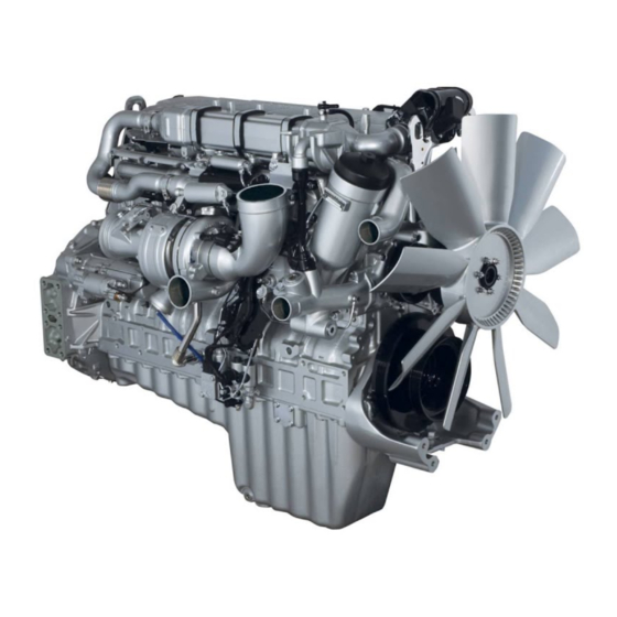
MBE4000 APPLICATION AND INSTALLATION ENGINE DESCRIPTION The MBE4000 engines are water-cooled, four-stroke, direct-injection diesel engines. The cylinders are arranged inline. See Figure 3-1 for the MBE4000 six-cylinder EGR engine. Figure 3-1 Typical MBE4000 Engine with EGR All information subject to change without notice. (Rev. 03/06) -
Page 32: Major Component Locations For Mbe4000 Egr Engines
3. EGR Hot Pipe 9. Front Lifter Bracket 4. EGR Shutoff Valve 5. Throttle Figure 3-2 Right Front View of MBE4000 EGR Engine All information subject to change without notice. (Rev. 03/06) 7SA250 0603 Copyright © 2006 DETROIT DIESEL CORPORATION... -
Page 33: Figure 3-3 Left Front View Of The Mbe4000 Egr Engine
7. Crankcase Breather (Hengst Filter) 4. EGR Modulated Control Valve 8. Charge Air Mixer Figure 3-3 Left Front View of the MBE4000 EGR Engine All information subject to change without notice. (Rev. 03/06) 7SA250 0603 Copyright © 2006 DETROIT DIESEL CORPORATION... -
Page 34: Engine Identification
filter housing on the right-hand side of the engine (See Figure 3-4 and Figure 3-5). Figure 3-4 Location of Engine Type Plate Figure 3-5 Engine Type Plate Detail All information subject to change without notice. (Rev. 03/06) 7SA250 0603 Copyright © 2006 DETROIT DIESEL CORPORATION... -
Page 35: Figure 3-6 Serial Number
DDEC-ECU label. The ten digit number is derived from the fourteen digit number (see Figure 3-6). Figure 3-6 Serial Number All information subject to change without notice. (Rev. 03/06) 7SA250 0603 Copyright © 2006 DETROIT DIESEL CORPORATION... -
Page 36: Emission Label
ENGINE AND ACCESSORY IDENTIFICATION EMISSION LABEL The MBE4000 engine is built in accordance with sound technological principles and based on state-of-the-art technology. It complies with appropriate United States Environmental Protection Agency (U.S. EPA) and California Air Resources Board (CARB) emission standards. An emission label is attached to the cylinder head cover, as required by law. -
Page 37: Air Inlet System
AIR INLET SYSTEM DESCRIPTION ............4- 3 INSTALLATION REQUIREMENTS ............4- 4 DESIGN GUIDELINES ................4-14 TESTING REQUIREMENTS ..............4-19 TEST ....................... 4-25 All information subject to change without notice. (Rev. 03/06) 7SA250 0603 Copyright © 2006 DETROIT DIESEL CORPORATION... -
Page 38: Air Inlet System
AIR INLET SYSTEM THIS PAGE INTENTIONALLY LEFT BLANK All information subject to change without notice. (Rev. 03/06) 7SA250 0603 Copyright © 2006 DETROIT DIESEL CORPORATION... -
Page 39: Air Inlet System Description
MBE4000 ON-HIGHWAY ENGINES All MBE4000 on-highway engines have a single turbocharger which supplies filtered air through a remote CAC to the air intake manifold. The MBE4000 CACs are generally located in front of or next to the engine radiator core. -
Page 40: Installation Requirements
4.2.1 DRY PAPER ELEMENT AIR CLEANERS Dry paper element type cleaners are recommended for use on Detroit Diesel engines. Alternate types of air filtration systems, such foam type (refer to section 4.2.1.4) and oil bath cleaners (refer to section 4.2.1.5), may be available in the aftermarket. -
Page 41: Medium-Duty Use Air Cleaner
8. Nut Assembly (Wing Nut and Washer Gasket) 4. Clamp Assembly 9. Restriction Indicator Fitting Cap 10. O-ring 5. Baffle Assembly Figure 4-1 Medium-duty Air Cleaner All information subject to change without notice. (Rev. 03/06) 7SA250 0603 Copyright © 2006 DETROIT DIESEL CORPORATION... -
Page 42: Heavy-Duty Use Air Cleaner
4. Lower Body Assembly 11. Gasket 12. Access Cover 5. Body Clamp 13. Wing Nut 6. O-ring 7. Upper Body Assembly Figure 4-2 Heavy-duty Air Cleaner All information subject to change without notice. (Rev. 03/06) 7SA250 0603 Copyright © 2006 DETROIT DIESEL CORPORATION... -
Page 43: Extra Heavy-Duty Use
2. Positive Pressure Plumbing Kit 6. Outlet Nozzle 7. Mounting Flange 3. Positive Pressure Self-cleaning Precleaner 4. Pamic Element Figure 4-3 Extra Heavy-duty Air Cleaner All information subject to change without notice. (Rev. 03/06) 7SA250 0603 Copyright © 2006 DETROIT DIESEL CORPORATION... -
Page 44: Foam Type Air Cleaners
Oil bath air cleaners generally have lower efficiencies and greater restriction to airflow than dry type air cleaners. Detroit Diesel Corporation (DDC) recognizes that oil bath air cleaners may be necessary in locations where dry type air cleaners are not readily available. Therefore, oil bath type air cleaners are acceptable when used according to the air cleaner manufacturer's guidelines and DDC air system requirements. -
Page 45: Auxiliary Precleaners
See Figure 4-4. Figure 4-4 Precleaner Centrifugal Action Precleaners may be used with the MBE4000 engines as long as the air inlet restriction requirements are met. The use of a precleaner may necessitate the use of a larger air cleaner. Inlet Screens An inlet screen may be used with an air cleaner when larger airborne material is encountered in an operating environment. -
Page 46: Rain Caps And Inlet Hoods
The installer should consult the supplier for specific recommendations. Care should be taken to ensure that the intake restriction is not raised above the allowable limit for clean air cleaners. 4-10 All information subject to change without notice. (Rev. 03/06) 7SA250 0603 Copyright © 2006 DETROIT DIESEL CORPORATION... -
Page 47: Air Cleaner Selection
Table 4-2 Air Inlet Restriction at Different Altitudes The reason for this reduction in allowable restriction is the lower air density at altitude. 4-11 All information subject to change without notice. (Rev. 03/06) 7SA250 0603 Copyright © 2006 DETROIT DIESEL CORPORATION... -
Page 48: Figure 4-6 Altitude Vs. Inlet Restriction
Compensate for the added restriction incurred from piping between the cleaner and the turbocharger inlet when the restriction indicator fits to the air cleaner tapping of a remote-mounted cleaner. 4-12 All information subject to change without notice. (Rev. 03/06) 7SA250 0603 Copyright © 2006 DETROIT DIESEL CORPORATION... -
Page 49: Pipework
Diffusers Make any necessary cross-sectional changes in the piping diameter gradually rather than using sudden expansions or contractions. Figure 4-7 Diffuser Configurations 4-13 All information subject to change without notice. (Rev. 03/06) 7SA250 0603 Copyright © 2006 DETROIT DIESEL CORPORATION... -
Page 50: Hose Connections
□ Temperature rise from ambient to turbo inlet Refer to section 14, “Technical Data,” for limits on each of these criteria for your specific engine. Contact Detroit Diesel Application Engineering for the latest information on specific engines. 4-14 All information subject to change without notice. (Rev. 03/06) -
Page 51: Maximum Air Inlet Flow
The first step in the design of the air inlet system is to determine the maximum air flow requirement for the engine. This information for the MBE4000 engines is listed in the “Technical Data” section of this manual (refer to section 14). -
Page 52: Charge Air Cooler
The maximum temperature differential between ambient air and intake manifold is available in the “Technical Data” section of this manual (refer to section 14). 4-16 All information subject to change without notice. (Rev. 03/06) 7SA250 0603 Copyright © 2006 DETROIT DIESEL CORPORATION... -
Page 53: Cleanliness
Charge air coolers have a cooling air flow restriction typically between 0.75 and 1.5 in. H O (.19 and .37 kPa). 4-17 All information subject to change without notice. (Rev. 03/06) 7SA250 0603 Copyright © 2006 DETROIT DIESEL CORPORATION... -
Page 54: Material
The inlet and outlet diameters of the header tanks should be the same as the pipework to and from the engine. A 3.0 in. (76.2 mm) minimum diameter is required for the MBE4000 engines. The tube ends require a 0.09 in. (2.3 mm) minimum bead to retain hose and clamp connections. -
Page 55: Winterfronts
These tests must be run on all new installations, engine repowers, or whenever modifications have been made to the engine, air inlet system, engine load, duty cycle, or environmental operating conditions. The Detroit Diesel End Product Questionnaire (EPQ) form must be completed. 4.4.1... -
Page 56: Pressure Measurement
(see Figure 4-9) to make a piezometer ring to measure static pressure in straight pipe sections. Figure 4-9 Static Pressure Tap 4-20 All information subject to change without notice. (Rev. 03/06) 7SA250 0603 Copyright © 2006 DETROIT DIESEL CORPORATION... - Page 57 □ Do not drop, drag, roll, or strike a cylinder forcefully. □ Always close valves completely when finished welding or cutting. 4-21 All information subject to change without notice. (Rev. 03/06) 7SA250 0603 Copyright © 2006 DETROIT DIESEL CORPORATION...
-
Page 58: Figure 4-10 Piezometer Ring
Figure 4-10 Piezometer Ring The instrumentation should be placed perpendicular to the plane of the bend where measurement on a bend is unavoidable. 4-22 All information subject to change without notice. (Rev. 03/06) 7SA250 0603 Copyright © 2006 DETROIT DIESEL CORPORATION... -
Page 59: Location
The maximum permitted inlet restriction for a system with a clean air cleaner is 10 in. H (2.5 kPa). The maximum permitted inlet restriction for a system with a dirty air cleaner is 22 in. H (5.5 kPa). 4-23 All information subject to change without notice. (Rev. 03/06) 7SA250 0603 Copyright © 2006 DETROIT DIESEL CORPORATION... -
Page 60: Maximum Temperature Rise-Ambient To Turbocharger Inlet
The temperature differential between the ambient temperature and the temperature at the turbocharger inlet (T ) needs to be determined. The maximum temperature differential for the MBE4000 engine can be found in the “Technical Data” section of this manual (refer to section 14). 4.4.4... -
Page 61: Charge Air Cooler System Restriction
P to determine pressure drop of the system. Two precision gauges may be used as desired. The maximum pressure drop for the MBE4000 engine is listed in the “Technical Data” section of this manual (refer to section 14). TEST Thorough preparations prior to testing will ensure accurate results. -
Page 62: Figure 4-12 Air Inlet Data Sheet For Air-To-Air Charge Cooled Engine
Diesel Application Engineering. Sample data sheets for the air inlet and charge air system tests are given below (see Figure 4-12). Figure 4-12 Air Inlet Data Sheet for Air-to-Air Charge Cooled Engine 4-26 All information subject to change without notice. (Rev. 03/06) 7SA250 0603 Copyright © 2006 DETROIT DIESEL CORPORATION... -
Page 63: Exhaust System
Section Page EXHAUST SYSTEM DESCRIPTION ............5- 3 INSTALLATION REQUIREMENTS ............5- 4 DESIGN REQUIREMENTS ..............5- 7 TESTING REQUIREMENTS ..............5- 8 All information subject to change without notice. (Rev. 03/06) 7SA250 0603 Copyright © 2006 DETROIT DIESEL CORPORATION... -
Page 64: Exhaust System
EXHAUST SYSTEM THIS PAGE INTENTIONALLY LEFT BLANK All information subject to change without notice. (Rev. 03/06) 7SA250 0603 Copyright © 2006 DETROIT DIESEL CORPORATION... -
Page 65: Exhaust System Description
The gases are then released through the exhaust pipes and the muffler to the atmosphere. All information subject to change without notice. (Rev. 03/06) 7SA250 0603 Copyright © 2006 DETROIT DIESEL CORPORATION... -
Page 66: Turbocharger
Adequate clearance must be provided for the complete exhaust system. The exhaust must not pass too close to the filters, fuel lines, fuel injection pump, starter, alternators, etc. The minimum required exhaust pipe inner diameter (I.D.) for a MBE4000 engine is listed in the “Technical Data” section of this manual (refer to section 14). -
Page 67: Back Pressure
The total back pressure must not exceed the maximum allowable value listed in the “Technical Data” section of this manual (refer to section 14. All information subject to change without notice. (Rev. 03/06) 7SA250 0603 Copyright © 2006 DETROIT DIESEL CORPORATION... -
Page 68: Noise
The turbine outlet uses a clamp, see the installation drawing for details (refer to section 15). 5.2.4 MATERIAL SPECIFICATIONS FOR PIPEWORK The minimum required exhaust pipe diameter for the MBE4000 engines is listed in the “Technical Data” section of this manual (refer to section 14). Pipework should be low carbon steel. -
Page 69: Design Requirements
MBE4000 APPLICATION AND INSTALLATION DESIGN REQUIREMENTS The exhaust systems for MBE4000 powered equipment must function under a variety of environmental conditions. Exposure to rain and snow and subjection to both thermal and mechanical stresses are inherent to vehicle or equipment operation. -
Page 70: Muffler Location
These tests must be run on all new installations, engine repowers, or whenever modifications have been made to the engines exhaust system. The appropriate section of the EPQ form must be completed. All information subject to change without notice. (Rev. 03/06) 7SA250 0603 Copyright © 2006 DETROIT DIESEL CORPORATION... -
Page 71: Measurement Of Exhaust Back Pressure
Use a piezometer ring to measure static pressure within 127 mm (5 in.) of the turbocharger discharge (see Figure 5-2and Figure 5-3). Figure 5-2 Piezometer Ring All information subject to change without notice. (Rev. 03/06) 7SA250 0603 Copyright © 2006 DETROIT DIESEL CORPORATION... -
Page 72: Measurement Of Exhaust Temperature
MEASUREMENT OF EXHAUST TEMPERATURE Use a precision thermocouple and an appropriate read-out device to measure temperatures. Thermocouples should be located downstream of the pressure taps. 5-10 All information subject to change without notice. (Rev. 03/06) 7SA250 0603 Copyright © 2006 DETROIT DIESEL CORPORATION... -
Page 73: Exhaust Gas Recirculation
6- 3 EGR COOLER ..................6- 4 EGR CONTROL VALVES ............... 6- 5 REED VALVES ..................6- 5 EGR MIXER .................... 6- 5 All information subject to change without notice. (Rev. 03/06) 7SA250 0603 Copyright © 2006 DETROIT DIESEL CORPORATION... -
Page 74: Exhaust Gas Recirculation
EXHAUST GAS RECIRCULATION THIS PAGE INTENTIONALLY LEFT BLANK All information subject to change without notice. (Rev. 03/06) 7SA250 0603 Copyright © 2006 DETROIT DIESEL CORPORATION... -
Page 75: System Description
□ Reed Valves (refer to section 6.4) □ EGR Mixer (refer to section 6.5) The MBE4000 engines for on-highway EPA 2004 regulation applications use a cooled EGR system. Exhaust gases from the front three cylinders are routed from the exhaust manifold through the EGR cooler, past control and reed valves, and mixed with the intake manifold charge air. -
Page 76: Egr Cooler
EXHAUST GAS RECIRCULATION See Figure 6-2 for an illustration of the MBE4000 engine with an EGR system. 1. Exhaust Gas Inlet Pipe 5. Mixer 2. EGR Shutoff Valve 6. Exhaust Gas Outlet Pipe 3. EGR Cooler 7. Reed Valves 4. Modulated EGR Valve... -
Page 77: Egr Control Valves
MBE4000 APPLICATION AND INSTALLATION EGR CONTROL VALVES There are two EGR valves on the MBE4000 – the EGR shutoff valve and the modulated EGR valve. The EGR valves regulate the flow of exhaust gases through the EGR system. The EGR shutoff valve is a pneumatically driven butterfly valve, located at the inlet to the EGR cooler. - Page 78 EXHAUST GAS RECIRCULATION THIS PAGE INTENTIONALLY LEFT BLANK All information subject to change without notice. (Rev. 03/06) 7SA250 0603 Copyright © 2006 DETROIT DIESEL CORPORATION...
-
Page 79: Charge Air Cooling Design Guidelines
FAN SYSTEM RECOMMENDATIONS AND FAN SELECTION ..... 7-27 7.14 RADIATOR COMPONENT DESIGN ............7-34 7.15 DIAGNOSTICS AND TROUBLESHOOTING .......... 7-53 7.16 MAINTENANCE ..................7-57 All information subject to change without notice. (Rev. 03/06) 7SA250 0603 Copyright © 2006 DETROIT DIESEL CORPORATION... - Page 80 COOLING SYSTEM THIS PAGE INTENTIONALLY LEFT BLANK All information subject to change without notice. (Rev. 03/06) 7SA250 0603 Copyright © 2006 DETROIT DIESEL CORPORATION...
-
Page 81: Cooling System Description
MBE4000 APPLICATION AND INSTALLATION COOLING SYSTEM DESCRIPTION The MBE4000 cooling system is comprised of two separate systems; the jacket water cooled system and the charge air cooler (CAC) system. Although these systems are separate, they usually share the same space which makes each system's performance dependent upon the other. -
Page 82: Figure 7-1 Thermostats Closed
COOLING SYSTEM Figure 7-1 Thermostats Closed All information subject to change without notice. (Rev. 03/06) 7SA250 0603 Copyright © 2006 DETROIT DIESEL CORPORATION... -
Page 83: Figure 7-2 Thermostats Open
MBE4000 APPLICATION AND INSTALLATION Figure 7-2 Thermostats Open All information subject to change without notice. (Rev. 03/06) 7SA250 0603 Copyright © 2006 DETROIT DIESEL CORPORATION... -
Page 84: Figure 7-3 Coolant Expansion
The vacuum unseats another valve in the radiator pressure cap, allowing the coolant to flow back into the radiator. All information subject to change without notice. (Rev. 03/06) 7SA250 0603 Copyright © 2006 DETROIT DIESEL CORPORATION... -
Page 85: Figure 7-4 Thermostat And Related Parts
Thermostat closing and opening temperatures are listed in the “Technical Data” section of this manual (refer to section 14). Properly operating thermostats are essential for efficient operation of the engine. All information subject to change without notice. (Rev. 03/06) 7SA250 0603 Copyright © 2006 DETROIT DIESEL CORPORATION... -
Page 86: Water Pump
The pump is mounted on the front of the engine block and is belt driven by the crankshaft pulley. TYPES OF COOLING SYSTEMS Radiator cooling systems can be classified into two broad categories: rapid warm-up and conventional. Only rapid warm-up systems are acceptable on the MBE4000. 7.5.1 RAPID WARM-UP COOLING SYSTEM The rapid warm-up cooling system eliminates coolant flow through the radiator core during... -
Page 87: Figure 7-5 Rapid Warm-Up Cooling System - Remote Tank, Cross Flow And Down Flow Radiators
MBE4000 APPLICATION AND INSTALLATION Figure 7-5 Rapid Warm-up Cooling System - Remote Tank, Cross Flow and Down Flow Radiators All information subject to change without notice. (Rev. 03/06) 7SA250 0603 Copyright © 2006 DETROIT DIESEL CORPORATION... -
Page 88: Figure 7-6 Rapid Warm-Up With Integral Top Tank
This type of system may experience slow warm-up or inability to maintain minimum operating temperatures during cold ambient operations. Detroit Diesel will not approve a conventional cooling system for the MBE4000. 7.5.3 AUXILIARY AIR-COOLED COOLER CORES Heat exchangers in addition to jacket water and charge air cooler radiators are quite often part of the total cooling system. -
Page 89: Air-To-Air Charge Cooling
At the beginning of the compression stroke, each cylinder is filled with clean, fresh air which provides for efficient combustion. 7-11 All information subject to change without notice. (Rev. 03/06) 7SA250 0603 Copyright © 2006 DETROIT DIESEL CORPORATION... -
Page 90: Figure 7-7 Typical Charge Air Cooler
Flexible rubber couplings and hose clamps are used to secure the duct work to the turbocharger, the CAC inlet and outlet, and the intake manifold. 7-12 All information subject to change without notice. (Rev. 03/06) 7SA250 0603 Copyright © 2006 DETROIT DIESEL CORPORATION... -
Page 91: Table 7-1 Maximum Engine Coolant Out Temperature
The water pump must not become air bound. NOTICE: An air bound pump cannot adequately circulate coolant. This can lead to overheating and severe engine damage. 7-13 All information subject to change without notice. (Rev. 03/06) 7SA250 0603 Copyright © 2006 DETROIT DIESEL CORPORATION... -
Page 92: Figure 7-8 Percent Increases In Volume For Water And Antifreeze Solution
Total cooling system coolant capacity must be known in order to determine the expansion and deaeration volumes required in the top tank. See Figure 7-8. Figure 7-8 Percent Increases in Volume for Water and Antifreeze Solution 7-14 All information subject to change without notice. (Rev. 03/06) 7SA250 0603 Copyright © 2006 DETROIT DIESEL CORPORATION... -
Page 93: Drawdown Capacity
Drawdown capacity is the amount of coolant which can be removed from the system before aereation or flow loss occurs. The drawdown capacity for MBE4000 engines is 10% of the total cooling capacity. System design must permit reasonable loss of coolant from the hot full level before aeration of the coolant begins. -
Page 94: Charge Air Cooling Requirements
Antifreeze concentration should not exceed 67% for ethylene glycol (50% for propylene glycol). Detroit Diesel requires SCAs be added to all cooling systems at initial fill and be maintained at the proper concentration. Follow SCA manufacturers' recommendations. Refer to Coolant Selections for Engine Cooling Systems (7SE0298), available on the DDC extranet. -
Page 95: End Product Questionnaire
A Detroit Diesel End Product Questionnaire (EPQ) must be completed on new installations, engine repowers, and installation modifications. Copies of the Detroit Diesel long and short EPQ forms can be found in the appendix of this manual. The short form may be used for ten or less units per year. -
Page 96: Engine Performance
Heat transfer capabilities must be adequate for the designated coolant, air temperatures, and flows. These capabilities should include reserve capacity to allow for cooling system deterioration. 7-18 All information subject to change without notice. (Rev. 03/06) 7SA250 0603 Copyright © 2006 DETROIT DIESEL CORPORATION... -
Page 97: Environmental And Operating Conditions
This controls engine oil temperature at a satisfactory level for good engine performance and reliability. Cab heater performance is adversely affected if coolant temperatures are not maintained. 7-19 All information subject to change without notice. (Rev. 03/06) 7SA250 0603 Copyright © 2006 DETROIT DIESEL CORPORATION... -
Page 98: Altitude
□ Torque converters □ Hydraulic oil coolers □ Air compressors □ Retarders □ Brake coolers □ Water cooled exhaust systems □ Exhaust gas coolers 7-20 All information subject to change without notice. (Rev. 03/06) 7SA250 0603 Copyright © 2006 DETROIT DIESEL CORPORATION... - Page 99 □ Use short and straight sections of hose only. Use formed tubes when bends are required. Otherwise the use of formed tubes is not recommended. 7-21 All information subject to change without notice. (Rev. 03/06) 7SA250 0603 Copyright © 2006 DETROIT DIESEL CORPORATION...
-
Page 100: Auxiliary Coolant Flow Path Circuitry
This will allow removal of trapped air and to help complete filling of the cooling system. 7-22 All information subject to change without notice. (Rev. 03/06) 7SA250 0603 Copyright © 2006 DETROIT DIESEL CORPORATION... -
Page 101: Installation Drawings
Air can also be introduced into the cooling system from a severely agitated or improperly designed top tank. 7-23 All information subject to change without notice. (Rev. 03/06) 7SA250 0603 Copyright © 2006 DETROIT DIESEL CORPORATION... - Page 102 DDC Applications Engineering. The use of untreated steel and other similar material is not approved because of rust formation. 7-24 All information subject to change without notice. (Rev. 03/06) 7SA250 0603 Copyright © 2006 DETROIT DIESEL CORPORATION...
- Page 103 A 101.6 mm (4 in.) minimum diameter is required for the MBE4000 engines. The tube ends require a 2.3 mm (0.09 in.) minimum bead to retain hose and clamp connections.
-
Page 104: Table 7-2 Heat Exchanger Materials, Construction, And Design Choices
□ Keep core thickness and fin density (fins per unit length) to a minimum. This keeps air flow restriction low, helps prevent plugging, and promotes easier core cleaning. □ Fin density in excess of 10 fins per inch should be reviewed with Detroit Diesel Application Engineering. - Page 105 □ Fan drive limits □ Fan speed limit □ Fan weight and support capabilities □ Fan spacers Fan tip speed in excess of 18,000 fpm should be reviewed with Detroit Diesel Application Engineering. 7-27 All information subject to change without notice. (Rev. 03/06)
-
Page 106: Figure 7-9 Blower Vs. Suction Fans
Fan rotation must also be correct. Figure 7-9 Blower vs. Suction Fans 7-28 All information subject to change without notice. (Rev. 03/06) 7SA250 0603 Copyright © 2006 DETROIT DIESEL CORPORATION... - Page 107 fins per inch. NOTE: Fin density in excess of 10 fins per inch should be reviewed with Detroit Diesel Application Engineering. Increasing core thickness increases the restriction to air flow. This condition causes fouling to occur faster.
- Page 108 The air side of the cooling system is critical and a change in the air flow will generally have a greater impact on cooling than a similar percentage change in coolant flow. 7-30 All information subject to change without notice. (Rev. 03/06) 7SA250 0603 Copyright © 2006 DETROIT DIESEL CORPORATION...
- Page 109 Consider components located behind the fan so air flow is not adversely affected or vibration introduced to the fan. These conditions will cause premature failures, or increased noise, or both. Fan height is also important. 7-31 All information subject to change without notice. (Rev. 03/06) 7SA250 0603 Copyright © 2006 DETROIT DIESEL CORPORATION...
-
Page 110: Figure 7-10 Fan Shroud Types
Do not exceed the design limits of any component when OEM components such as fans, fan drives, spacers, etc. are attached to Detroit Diesel supplied components (fan hub and pulley assemblies). Vibration tests must be performed when the customer wants to use a fan system not previously approved by DDC. - Page 111 All monitoring, warning, and shutdown devices should be properly located and in good working condition. 7-33 All information subject to change without notice. (Rev. 03/06) 7SA250 0603 Copyright © 2006 DETROIT DIESEL CORPORATION...
-
Page 112: Down Flow And Cross Flow Radiators
It is essential that vent lines go to the fill tank with the cap. Consult DDC Application Engineering for assistance in applying horizontal radiators. 7-34 All information subject to change without notice. (Rev. 03/06) 7SA250 0603 Copyright © 2006 DETROIT DIESEL CORPORATION... -
Page 113: Rapid Warm-Up Deaeration Tank - Down Flow Radiator
□ Maximum allowable static head pressure is 35 ft of water column □ Installations where flow rate restrictions cannot be met may require using an inline pump 7-35 All information subject to change without notice. (Rev. 03/06) 7SA250 0603 Copyright © 2006 DETROIT DIESEL CORPORATION... -
Page 114: Integral Top Tank
The following top tank component guidelines are provided to assist in the design of a new tank, to critique existing tanks, and to troubleshoot problem cooling systems. See Figure 7-12. Figure 7-12 Rapid Warm-up Down Flow Radiator Top Tank 7-36 All information subject to change without notice. (Rev. 03/06) 7SA250 0603 Copyright © 2006 DETROIT DIESEL CORPORATION... - Page 115 (6%) and deaeration (2%) volume. Table 7-4 Top Tank Component Guidelines — Standpipe(s), Baffle, Vortex Baffle, Fill Line and Connections, Vent Line, and Radiator Inlet 7-37 All information subject to change without notice. (Rev. 03/06) 7SA250 0603 Copyright © 2006 DETROIT DIESEL CORPORATION...
- Page 116 □ A sight glass in the radiator top tank to determine proper coolant level will eliminate unnecessary removal of the radiator cap. 7-38 All information subject to change without notice. (Rev. 03/06) 7SA250 0603 Copyright © 2006 DETROIT DIESEL CORPORATION...
-
Page 117: Remote Tank
The guidelines for the radiator inlet tank are listed in Table 7-6. Figure 7-13 Remote Surge Tank Design for Rapid Warm-up Cooling System 7-39 All information subject to change without notice. (Rev. 03/06) 7SA250 0603 Copyright © 2006 DETROIT DIESEL CORPORATION... -
Page 118: Radiator Bottom Tank
□ Locate the coolant opening diagonally opposite the inlet tank opening or as far away as is practical. This provides uniform distribution of the coolant across the core and prevents short circuiting; see Figure 7-15. 7-40 All information subject to change without notice. (Rev. 03/06) 7SA250 0603 Copyright © 2006 DETROIT DIESEL CORPORATION... -
Page 119: Figure 7-15 Coolant Inlet/Outlet Locations
Radiator Outlet Contour □ Depth of the tank should be no less than the diameter of the outlet pipe to minimize restriction. 7-41 All information subject to change without notice. (Rev. 03/06) 7SA250 0603 Copyright © 2006 DETROIT DIESEL CORPORATION... -
Page 120: Coolant Pressure Control Caps And Relief Valves
) of the rating stamped on top of the cap/valve. The valve will lift off the seat, see Figure 7-17, as pressure exceeds the specified rating. 7-42 All information subject to change without notice. (Rev. 03/06) 7SA250 0603 Copyright © 2006 DETROIT DIESEL CORPORATION... -
Page 121: Figure 7-17 Pressure Control Cap - Pressure Valve Open
“Technical Data” section of this manual (refer to section 14). Consider higher pressure rated caps for operation at increased altitudes. 7-43 All information subject to change without notice. (Rev. 03/06) 7SA250 0603 Copyright © 2006 DETROIT DIESEL CORPORATION... -
Page 122: Thermostat
The coolant temperature monitor may not respond fast enough to prevent engine damage if a large quantity of coolant is suddenly lost, or if the water pump becomes air bound. Engine Coolant Level Sensors are required with MBE4000 engines. Temperature Gauges: Every temperature gauge should have sufficient markings to allow an operator to determine actual operating temperature. - Page 123 The recommended temperature settings of the various coolant sensor devices can be seen in the following illustration (see Figure 7-19 ). Figure 7-19 Nominal Settings For Coolant Temperature Control Devices — 190° 7-45 All information subject to change without notice. (Rev. 03/06) 7SA250 0603 Copyright © 2006 DETROIT DIESEL CORPORATION...
-
Page 124: Coolant Recovery System
Figure 7-20 Cooling System Design (Warm-up -- Closed Thermostat) 7-46 All information subject to change without notice. (Rev. 03/06) 7SA250 0603 Copyright © 2006 DETROIT DIESEL CORPORATION... - Page 125 flow into the coolant recovery tank. See Figure 7-20 and Figure 7-21. 7-47 All information subject to change without notice. (Rev. 03/06) 7SA250 0603 Copyright © 2006 DETROIT DIESEL CORPORATION...
- Page 126 The total coolant volume decreases as the engine coolant temperature falls. See Figure 7-22. Figure 7-22 Cooling System Design (Cool-down -- Closed Thermostat) 7-48 All information subject to change without notice. (Rev. 03/06) 7SA250 0603 Copyright © 2006 DETROIT DIESEL CORPORATION...
- Page 127 Wear adequate protective clothing (face shield, rubber gloves, apron, and boots). Remove the cap slowly to relieve pressure. 7-49 All information subject to change without notice. (Rev. 03/06) 7SA250 0603 Copyright © 2006 DETROIT DIESEL CORPORATION...
- Page 128 Unacceptable Top Tank Design Connect the deaeration line as high as possible to the top tank when using a coolant recovery system. 7-50 All information subject to change without notice. (Rev. 03/06) 7SA250 0603 Copyright © 2006 DETROIT DIESEL CORPORATION...
-
Page 129: Cold Weather Operating Optimization
To maximize the available heat energy of the cooling system: □ Use optimized Rapid Warm-up System □ Set coolant antifreeze concentration correctly 7-51 All information subject to change without notice. (Rev. 03/06) 7SA250 0603 Copyright © 2006 DETROIT DIESEL CORPORATION... -
Page 130: Heater Circuit
The recommended heater connect points are listed in the “Technical Data” section of this manual (refer to section 14). 7.14.3 COOLANT HEATERS Information on coolant heaters can be obtained from the Detroit Diesel Application Engineering. 7.14.4 MULTI-DUTY CYCLE Cooling systems must perform satisfactorily under all operating modes. Consideration must be given when an engine is used for prime power under several duty cycles such as cranes, drill/pumping rigs, etc. -
Page 131: Diagnostics And Troubleshooting
3. Check for insufficient coolant flow. The following may be causes of insufficient coolant flow: Thermostat -- Stuck, sluggish, worn, broken □ 7-53 All information subject to change without notice. (Rev. 03/06) 7SA250 0603 Copyright © 2006 DETROIT DIESEL CORPORATION... - Page 132 7. Also check the following: Increased heat rejection or engine horsepower upgrade □ Engine, installation, or cooling system modified □ 7-54 All information subject to change without notice. (Rev. 03/06) 7SA250 0603 Copyright © 2006 DETROIT DIESEL CORPORATION...
-
Page 133: Cold Running Engine (Overcooling)
1. Check coolant-side cause, low flow, by investigating the following: Supply and return lines not connected to proper locations on the engine □ 7-55 All information subject to change without notice. (Rev. 03/06) 7SA250 0603 Copyright © 2006 DETROIT DIESEL CORPORATION... - Page 134 Heat loss to outside can be minimized by using thermo windows, reducing exposed metal surfaces, increasing insulation usage, etc. 7-56 All information subject to change without notice. (Rev. 03/06) 7SA250 0603 Copyright © 2006 DETROIT DIESEL CORPORATION...
-
Page 135: Maintenance
67% for ethylene glycol (50% for propylene glycol). Detroit Diesel requires SCAs be added to all cooling systems at initial fill and be maintained at the proper concentration. Follow SCA manufacturers' recommendations. - Page 136 COOLING SYSTEM THIS PAGE INTENTIONALLY LEFT BLANK 7-58 All information subject to change without notice. (Rev. 03/06) 7SA250 0603 Copyright © 2006 DETROIT DIESEL CORPORATION...
-
Page 137: Fuel System
MBE4000 APPLICATION AND INSTALLATION FUEL SYSTEM Section Page FUEL SYSTEM DESCRIPTION .............. 8- 3 FUEL SYSTEM EQUIPMENT/INSTALLATION GUIDELINES ....8- 5 FUEL SELECTION .................. 8-10 All information subject to change without notice. (Rev. 03/06) 7SA250 0603 Copyright © 2006 DETROIT DIESEL CORPORATION... - Page 138 FUEL SYSTEM THIS PAGE INTENTIONALLY LEFT BLANK All information subject to change without notice. (Rev. 03/06) 7SA250 0603 Copyright © 2006 DETROIT DIESEL CORPORATION...
-
Page 139: Fuel System Description
The DDEC-ECU sends a signal which activates the injector solenoid and determines the timing and amount of fuel delivered to the engine. All information subject to change without notice. (Rev. 03/06) 7SA250 0603 Copyright © 2006 DETROIT DIESEL CORPORATION... - Page 140 FUEL SYSTEM For a schematic diagram of a typical fuel system, see Figure 8-1. Figure 8-1 MBE4000 Fuel System Schematic Diagram All information subject to change without notice. (Rev. 03/06) 7SA250 0603 Copyright © 2006 DETROIT DIESEL CORPORATION...
-
Page 141: Fuel System Equipment/Installation Guidelines
These baffles should have passageways which allow the fuel to maintain an even level throughout the tank(s). The tank(s) should have a readily accessible drain valve at the bottom for easy removal of contaminants. All information subject to change without notice. (Rev. 03/06) 7SA250 0603 Copyright © 2006 DETROIT DIESEL CORPORATION... -
Page 142: Capacity
A sludge drain must be provided at the lowest point. The tank(s) must have a vent which meets applicable regulations. A stand pipe in the tank fuel return must be utilized on MBE4000 engines. A properly designed fuel tank may be seen in the following illustration (see Figure 8-2). -
Page 143: Position
filter. This will prevent the tank(s) from draining. A check valve in the fuel spill prevents supply side fuel from draining back into the tank(s) in a tank-below-engine installation. All information subject to change without notice. (Rev. 03/06) 7SA250 0603 Copyright © 2006 DETROIT DIESEL CORPORATION... -
Page 144: Options
8.2.2 FUEL FILTER CONFIGURATION Fuel filter requirements for the MBE4000 engines may be found in DDC publication 7SE270. Care should be taken not to exceed the maximum engine fuel inlet restriction17.7 in. Hg (600 mBar) under any conditions, 10.29 in. Hg (350 mBar) maximum for clean filters. The fuel inlet restriction must be measured before the main filter. -
Page 145: Material
A fuel water separator is required. The total fuel inlet system may not exceed the maximum restriction of 10.29 in. Hg (350 mBar). All information subject to change without notice. (Rev. 03/06) 7SA250 0603 Copyright © 2006 DETROIT DIESEL CORPORATION... -
Page 146: Fuel Selection
For information on fuel selection, refer to DDC publication 7SE270, “Lubricating Oil, Fuel and Filters.” 8-10 All information subject to change without notice. (Rev. 03/06) 7SA250 0603 Copyright © 2006 DETROIT DIESEL CORPORATION... -
Page 147: Lubrication System
INSTALLATION REQUIREMENTS ............9- 7 COMPONENT OPTIONS ................ 9- 8 OPERATION AND MAINTENANCE ............9-10 OIL FILTER CONFIGURATION .............. 9-10 OIL CENTRIFUGE .................. 9-10 All information subject to change without notice. (Rev. 03/06) 7SA250 0603 Copyright © 2006 DETROIT DIESEL CORPORATION... - Page 148 LUBRICATION SYSTEM THIS PAGE INTENTIONALLY LEFT BLANK All information subject to change without notice. (Rev. 03/06) 7SA250 0603 Copyright © 2006 DETROIT DIESEL CORPORATION...
-
Page 149: Lubrication System Description
□ Oil level dipstick □ Oil pan □ Ventilation A schematic of the MBE4000 lubricating system is shown in the following illustration (see Figure 9-1). All information subject to change without notice. (Rev. 03/06) 7SA250 0603 Copyright © 2006 DETROIT DIESEL CORPORATION... - Page 150 LUBRICATION SYSTEM Figure 9-1 Typical MBE4000 Lubrication System Schematic All information subject to change without notice. (Rev. 03/06) 7SA250 0603 Copyright © 2006 DETROIT DIESEL CORPORATION...
- Page 151 (see Figure 9-2). Figure 9-2 Typical MBE4000 Lubrication System There are a wide variety of options for location of gage, fill and breather components. All information subject to change without notice. (Rev. 03/06) 7SA250 0603 Copyright © 2006 DETROIT DIESEL CORPORATION...
-
Page 152: Lubrication Oil Selection
DDC publication 7SE270, “Lubricating Oils, Fuel, and Filters,” available on the DDC extranet LUBRICATION FILTER The MBE4000 engine has a vertical oil filter attached to the engine (see Figure 9-3). Figure 9-3 Vertical Oil Filter When the engine is installed, the lubricating oil filter and the oil drain plug in the oil pan must be... -
Page 153: Engine Component Oil Supply Requirements
MBE4000 APPLICATION AND INSTALLATION The micron rating of the oil filters used on the MBE4000 engine is given in DDC publication 7SE270, “Lubricating Oils, Fuel, and Filters” available on the DDC extranet. ENGINE COMPONENT OIL SUPPLY REQUIREMENTS There are also components mounted externally on the engine which are lubricated by the engine lubrication system. -
Page 154: Oil Sampling Valve
Detroit Diesel also provides a variety of oil fill options at various locations on the engine. A rocker cover oil fill is standard on all MBE4000 engines. Side-mounted tube fill options are also available, as well as an adapter for OEM-installed fill tubes. -
Page 155: Oil Immersion Heaters
Sensor-compatible oil pans. The sensor is installed at DDC and requires no subsequent calibration or maintenance. All wiring for this sensor is also factory-installed at DDC. Operation of the EOL Sensor is described in more detail in the DDEC for MBE 900 and MBE4000 Application and Installation manual (7SA825). -
Page 156: Operation And Maintenance
FIRST TIME START MBE4000 engines are shipped from the factory with full oil filters and a minimal amount of oil in the sump. The engine needs to be filled with oil to its high limit previous to a first time start. -
Page 157: Electrical System
MBE4000 APPLICATION AND INSTALLATION ELECTRICAL SYSTEM Section Page 10.1 ELECTRICAL SYSTEM DESCRIPTION ..........10- 2 10.2 INSTALLATION GUIDELINES ..............10- 3 10-1 All information subject to change without notice. (Rev. 03/06) 7SA250 0603 Copyright © 2006 DETROIT DIESEL CORPORATION... -
Page 158: Electrical System Description
□ Battery charging alternator (Alternator) □ Voltage regulator (generally integral to the alternator) □ Storage battery(s) □ Ignition switch Figure 10-1 Engine Electrical System 10-2 All information subject to change without notice. (Rev. 03/06) 7SA250 0603 Copyright © 2006 DETROIT DIESEL CORPORATION... -
Page 159: Installation Guidelines
filler caps to leak acid fumes, so cable inspection and cleaning are infrequent. Deep Cycle Batteries Deep cycle batteries are used for applications like electric drive carts, and are not recommended for engine starting. 10-3 All information subject to change without notice. (Rev. 03/06) 7SA250 0603 Copyright © 2006 DETROIT DIESEL CORPORATION... -
Page 160: Table 10-1 Minimum Battery Capacity For Acceptable Engine Cranking
27°C (80°F). The recommended battery carrier designs are: □ Top crossbar □ Top mid-frame □ Top picture frame □ Angled J-bolt 10-4 All information subject to change without notice. (Rev. 03/06) 7SA250 0603 Copyright © 2006 DETROIT DIESEL CORPORATION... - Page 161 MBE4000 APPLICATION AND INSTALLATION See Figure 10-2. Figure 10-2 Battery Retainers 10-5 All information subject to change without notice. (Rev. 03/06) 7SA250 0603 Copyright © 2006 DETROIT DIESEL CORPORATION...
-
Page 162: Cranking Motor
The cranking motor drive pinion and the engine flywheel ring gear must be matched to provide positive engagement and to avoid clashing of the gear teeth. 10-6 All information subject to change without notice. (Rev. 03/06) 7SA250 0603 Copyright © 2006 DETROIT DIESEL CORPORATION... -
Page 163: Alternator
Even though these alternators are referred to as “one wire systems", a separate ground return line should be used from the alternator to the battery. 10-7 All information subject to change without notice. (Rev. 03/06) 7SA250 0603 Copyright © 2006 DETROIT DIESEL CORPORATION... - Page 164 ELECTRICAL SYSTEM The MBE4000 alternator is typically front-mounted and driven Refer to section for accessory drive information. Because the regulator is contained within the alternator, relying on the frame for ground return can result in incorrect voltage sensing by the regulator and, as a result, incorrect alternator output.
-
Page 165: Alternator Mounting
10-9 All information subject to change without notice. (Rev. 03/06) 7SA250 0603 Copyright © 2006 DETROIT DIESEL CORPORATION... -
Page 166: Wiring
□ Frame area where ground connection is made should be stripped of paint and tinned to prevent corrosion. □ Recommended battery cable connections to the frame have hardened steel flat washers with a locking nut. 10-10 All information subject to change without notice. (Rev. 03/06) 7SA250 0603 Copyright © 2006 DETROIT DIESEL CORPORATION... -
Page 167: Cable Loss Test Procedure
8. Adjust load to 500 amps (250 amps if a 24 V system). 9. Measure motor voltage. 10. Turn off load. 10-11 All information subject to change without notice. (Rev. 03/06) 7SA250 0603 Copyright © 2006 DETROIT DIESEL CORPORATION... -
Page 168: Measuring Circuit Resistance
(see Figure 10-4). corrective measures such as cleaning the connections, reducing the number of connections, or increasing wire gage will have to be taken. Figure 10-4 Cable Resistance 10-12 All information subject to change without notice. (Rev. 03/06) 7SA250 0603 Copyright © 2006 DETROIT DIESEL CORPORATION... -
Page 169: Table 10-2 Maximum Circuit Resistance
12 V system 0.0012 ohm 12 V high output system 0.00075 ohm 24 V system 0.002 ohm Table 10-2 Maximum Circuit Resistance 10-13 All information subject to change without notice. (Rev. 03/06) 7SA250 0603 Copyright © 2006 DETROIT DIESEL CORPORATION... - Page 170 ELECTRICAL SYSTEM THIS PAGE INTENTIONALLY LEFT BLANK 10-14 All information subject to change without notice. (Rev. 03/06) 7SA250 0603 Copyright © 2006 DETROIT DIESEL CORPORATION...
-
Page 171: Mounting System
SOLID MOUNTING SYSTEMS ............... 11- 5 11.3 FLEXIBLE MOUNTING SYSTEMS ............11- 6 11.4 INSTALLATION CHECK LIST ..............11- 9 11.5 ENGINE SUPPORT ................11-10 11-1 All information subject to change without notice. (Rev. 03/06) 7SA250 0603 Copyright © 2006 DETROIT DIESEL CORPORATION... -
Page 172: Mounting System Description
The purpose of the engine mounting system is to keep the transfer of engine vibrations to the supporting structure at the lowest level possible. This section describes the functions, design, and application for the mounting system of a Detroit Diesel MBE4000 engine. The major functional requirements of an engine mounting system are: □... -
Page 173: Three-Point Mounting
Some MBE4000 engine flywheel housings have mounting pads. At the rear of the engine a bracket is attached to each side of the flywheel housing with the driven mechanism flange mounted to the engine. -
Page 174: Four-Point Mounting
MBE4000 engine blocks have mounting pads on each side so that four mounting brackets can be applied. Some MBE4000 engine Flywheel housings also have mounting pads. Sometimes the rear mounts are attachable to the sides of the driven component, but this depends on the resulting bending moment at RFB. -
Page 175: Solid Mounting Systems
□ Control the bending moment at the rear of the cylinder block by placement of the rear mount or cradle (refer to section11.5). 11-5 All information subject to change without notice. (Rev. 03/06) 7SA250 0603 Copyright © 2006 DETROIT DIESEL CORPORATION... -
Page 176: Flexible Mounting Systems
6. Desired amount of isolation if known, usually a minimum of 90%, and 96-98% for generators in buildings. 7. Any expected shock or impact loads described in g's and direction. 11-6 All information subject to change without notice. (Rev. 03/06) 7SA250 0603 Copyright © 2006 DETROIT DIESEL CORPORATION... -
Page 177: Method A
For more details and formulas to use in your calculations, refer to Barry Controls bulletin IOEM1, or Lord Manufacturing bulletin PC2201o. The suitability of the selected mounts should still be confirmed with the manufacturer. Detroit Diesel assumes no responsibility for the resilient mounting system performance. -
Page 178: Method B
5. Refer to the catalog for the desired mount that has that spring rate, or close to it. Recheck its suitability by repeating the steps in Method A. 11-8 All information subject to change without notice. (Rev. 03/06) 7SA250 0603 Copyright © 2006 DETROIT DIESEL CORPORATION... -
Page 179: Installation Check List
4. For mounting systems other than three-point the load at each mount should be balanced or adjusted to prevent excessive loads at the mountings and high engine vibration levels. 11-9 All information subject to change without notice. (Rev. 03/06) 7SA250 0603 Copyright © 2006 DETROIT DIESEL CORPORATION... -
Page 180: Engine Support
See Figure 11-4 to determine the distance of rear mounts to achieve a zero bending moment at the rear of the cylinder block. Figure 11-4 Distance of Rear Mounts for Zero Bending Moments 11-10 All information subject to change without notice. (Rev. 03/06) 7SA250 0603 Copyright © 2006 DETROIT DIESEL CORPORATION... - Page 181 See Figure 11-5 to determine the bending moment at the rear of the cylinder block when engine mount locations are fixed. Figure 11-5 Bending Moment for Fixed Mounting System 11-11 All information subject to change without notice. (Rev. 03/06) 7SA250 0603 Copyright © 2006 DETROIT DIESEL CORPORATION...
- Page 182 MOUNTING SYSTEM THIS PAGE INTENTIONALLY LEFT BLANK 11-12 All information subject to change without notice. (Rev. 03/06) 7SA250 0603 Copyright © 2006 DETROIT DIESEL CORPORATION...
-
Page 183: Torsional Analysis
MBE4000 APPLICATION AND INSTALLATION TORSIONAL ANALYSIS Section Page 12.1 OVERVIEW ..................... 12- 2 12.2 MASS ELASTIC ..................12- 2 12-1 All information subject to change without notice. (Rev. 03/06) 7SA250 0603 Copyright © 2006 DETROIT DIESEL CORPORATION... -
Page 184: Overview
12.2 MASS ELASTIC MBE4000 specific mass elastic data is available. This data can be requested from DDC for special use. Mass elastic system data is confidential and must be handled with care. To request this information contact DDC Application Engineering. -
Page 189: Engine Electronic Controls
VEHICLE CONTROL UNIT — ON-HIGHWAY ........13- 4 13.4 VEHICLE INTERFACE HARNESS ............13- 6 13.5 ENGINE HARNESS ................13- 7 13.6 SYSTEM SENSORS ................13- 8 13-1 All information subject to change without notice. (Rev. 03/06) 7SA250 0603 Copyright © 2006 DETROIT DIESEL CORPORATION... -
Page 190: Overview
For additional and in-depth information about DDEC for MBE 900 and MBE4000, refer to DDEC for MBE 900 and MBE4000 Application and Installation (7SA825) available on the DDC extranet. -
Page 191: Ddec-Ecu - Engine-Resident Control Unit
The data is then compared to the parameters stored in the DDEC-ECU. From these data, quantity and timing of injection are calculated and the unit pumps are actuated accordingly through the solenoid valves. 13-3 All information subject to change without notice. (Rev. 03/06) 7SA250 0603 Copyright © 2006 DETROIT DIESEL CORPORATION... -
Page 192: Vehicle Control Unit - On-Highway
VIH and should not be parallel to the VIH. This will eliminate coupling electromagnetic energy from other systems into the VIH. 13-4 All information subject to change without notice. (Rev. 03/06) 7SA250 0603 Copyright © 2006 DETROIT DIESEL CORPORATION... - Page 193 (for example, the anti-lock brake system, transmission controllers). From this data, instructions are computed for controlling the engine and transmitted to the DDEC-ECU via the proprietary datalink. 13-5 All information subject to change without notice. (Rev. 03/06) 7SA250 0603 Copyright © 2006 DETROIT DIESEL CORPORATION...
-
Page 194: Vehicle Interface Harness
A schematic of a on-highway VIH is shown in the following illustration (see see Figure 13-4). Figure 13-4 Typical MBE4000 Vehicle Interface Harness 13-6 All information subject to change without notice. (Rev. 03/06) 7SA250 0603 Copyright © 2006 DETROIT DIESEL CORPORATION... -
Page 195: Engine Harness
The Engine Harness (EH) facilitates the communication of engine sensor input to the DDEC-ECU (Figure 13-5 for the EGR engine). Figure 13-5 A Typical MBE4000 EGR Engine Harness 13-7 All information subject to change without notice. (Rev. 03/06) 7SA250 0603 Copyright © 2006 DETROIT DIESEL CORPORATION... -
Page 196: System Sensors
7. Supply Fuel Temperature Sensor 4. Crankshaft Position Sensor 8. Engine Oil Pressure/Temperature Sensor Figure 13-6 Sensor Location on the MBE4000 EGR Engine 13-8 All information subject to change without notice. (Rev. 03/06) 7SA250 0603 Copyright © 2006 DETROIT DIESEL CORPORATION... - Page 197 MBE4000 APPLICATION AND INSTALLATION Two sensors are not easily visible from the left-hand side of the MBE4000 engine. The Intake Manifold Pressure/Temperature Sensor is located on the right-hand side of the charge air manifold, behind the #2 cylinder head. The Engine Oil Pressure/Temperature Sensor is located at the base of the oil filter.
- Page 198 ENGINE ELECTRONIC CONTROLS THIS PAGE INTENTIONALLY LEFT BLANK 13-10 All information subject to change without notice. (Rev. 03/06) 7SA250 0603 Copyright © 2006 DETROIT DIESEL CORPORATION...
- Page 199 MBE4000 APPLICATION AND INSTALLATION TECHNICAL DATA This information is available by contacting DDC Application Engineering. 14-1 All information subject to change without notice. (Rev. 03/06) 7SA250 0603 Copyright © 2006 DETROIT DIESEL CORPORATION...
- Page 200 TECHNICAL DATA THIS PAGE INTENTIONALLY LEFT BLANK 14-2 All information subject to change without notice. (Rev. 03/06) 7SA250 0603 Copyright © 2006 DETROIT DIESEL CORPORATION...
- Page 201 MBE4000 APPLICATION AND INSTALLATION INSTALLATION DRAWINGS This information is available by contacting DDC Application Engineering. 15-1 All information subject to change without notice. (Rev. 03/06) 7SA250 0603 Copyright © 2006 DETROIT DIESEL CORPORATION...
- Page 202 INSTALLATION DRAWINGS THIS PAGE INTENTIONALLY LEFT BLANK 15-2 All information subject to change without notice. (Rev. 03/06) 7SA250 0603 Copyright © 2006 DETROIT DIESEL CORPORATION...
- Page 203 MBE4000 APPLICATION AND INSTALLATION OPTIONS This information is available by contacting DDC Application Engineering. 16-1 All information subject to change without notice. (Rev. 03/06) 7SA250 0603 Copyright © 2006 DETROIT DIESEL CORPORATION...
- Page 204 OPTIONS THIS PAGE INTENTIONALLY LEFT BLANK 16-2 All information subject to change without notice. (Rev. 03/06) 7SA250 0603 Copyright © 2006 DETROIT DIESEL CORPORATION...
-
Page 205: Effects Of Environmental Conditions
OVERVIEW ..................... 17- 2 17.2 AIR INLET TEMPERATURE ..............17- 2 17.3 EXHAUST BACK PRESSURE ..............17- 3 17.4 ALTITUDE ....................17- 3 17-1 All information subject to change without notice. (Rev. 03/06) 7SA250 0603 Copyright © 2006 DETROIT DIESEL CORPORATION... -
Page 206: Overview
This section includes deratings for: □ Air Inlet Temperature □ Exhaust □ Altitude MBE4000 engine power is not affected by air inlet restriction, fuel inlet restrictions, fuel temperature, and barometric pressure within the range of normal operational conditions. 17.2 AIR INLET TEMPERATURE High inlet air temperature to the engine can cause loss of power and heat problems with the cooling system, the lubricating oil and hydraulic oil systems. -
Page 207: Exhaust Back Pressure
The loss of power is not normally important at altitudes of less than 150 m (500 ft) above sea level. The degree of power loss at higher altitudes is determined by the altitude and the fuel injection specification needed. 17-3 All information subject to change without notice. (Rev. 03/06) 7SA250 0603 Copyright © 2006 DETROIT DIESEL CORPORATION... - Page 208 EFFECTS OF ENVIRONMENTAL CONDITIONS THIS PAGE INTENTIONALLY LEFT BLANK 17-4 All information subject to change without notice. (Rev. 03/06) 7SA250 0603 Copyright © 2006 DETROIT DIESEL CORPORATION...
-
Page 209: Engine Brake Systems
18.1 OVERVIEW ..................... 18- 2 18.2 CONSTANT-THROTTLE VALVES WITH EXHAUST BRAKE ....18- 2 18.3 CONSTANT-THROTTLE VALVES WITH TURBOBRAKE (OPTIONAL) 18- 2 18-1 All information subject to change without notice. (Rev. 03/06) 7SA250 0603 Copyright © 2006 DETROIT DIESEL CORPORATION... -
Page 210: Overview
18.1 OVERVIEW MBE4000 engines can be equipped with an exhaust brake on the turbocharger in conjunction with constant-throttle valves in the cylinder head to increase braking performance. The two systems operate independently of each other. Both are standard on the MBE4000. - Page 211 MBE4000 APPLICATION AND INSTALLATION Figure 18-1 Turbobrake Figure 18-2 Turbo Brake Off and On 18-3 All information subject to change without notice. (Rev. 03/06) 7SA250 0603 Copyright © 2006 DETROIT DIESEL CORPORATION...
- Page 212 ENGINE BRAKE SYSTEMS THIS PAGE INTENTIONALLY LEFT BLANK 18-4 All information subject to change without notice. (Rev. 03/06) 7SA250 0603 Copyright © 2006 DETROIT DIESEL CORPORATION...
-
Page 213: Accessory Drives
MBE4000 APPLICATION AND INSTALLATION ACCESSORY DRIVES Section Page 19.1 FEPTO ACCESSORY DRIVES .............. 19- 2 19.2 REPTO ACCESSORY DRIVES .............. 19- 3 19-1 All information subject to change without notice. (Rev. 03/06) 7SA250 0603 Copyright © 2006 DETROIT DIESEL CORPORATION... -
Page 214: Fepto Accessory Drives
19.1 FEPTO ACCESSORY DRIVES A Front Engine Power Take-off (FEPTO) is available on the MBE4000 engine (see Figure 19-1 and see Figure 19-2). The FEPTO is adaptable to a Spicer 1350/1410 drive shaft. The torque and horsepower limit of the FEPTO are listed in Table 19-1. -
Page 215: Repto Accessory Drives
REPTO ACCESSORY DRIVES The Rear Engine Power Take-off (REPTO) accessory drive is available as an option on the MBE4000 engine. This drive provides continuous live power anytime the engine is operating. The REPTO drives are listed in Table 19-2. Rotation... - Page 216 ACCESSORY DRIVES Figure 19-3 Typical MBE4000 REPTO Configuration Figure 19-4 REPTO Torsional Coupling 19-4 All information subject to change without notice. (Rev. 03/06) 7SA250 0603 Copyright © 2006 DETROIT DIESEL CORPORATION...
- Page 217 The overall installation dimension for engines equipped with REPTO drives does not change. See Figure 19-5 and Figure 19-6. Figure 19-5 REPTO Rear View, Figure 19-6 REPTO, Left Side View 19-5 All information subject to change without notice. (Rev. 03/06) 7SA250 0603 Copyright © 2006 DETROIT DIESEL CORPORATION...
-
Page 218: Table 19-3 Repto Installation Analysis Requirements
ACCESSORY DRIVES NOTE: Installations using REPTO drives require prior approval from Detroit Diesel Application Engineering. The following forms should be submitted to DDC Application Engineering for approval. □ Torsional Analysis (7SA0666) refer to section 12 for a copy of this form. -
Page 219: Appendix A: Abbreviations / Acronyms
Revolutions per Minute Society of Automotive Engineers Supplemental Coolant Additive Total Base Number U.S. EPA United States Environmental Protection Agency Vehicle Interface Harness All information subject to change without notice. (Rev. 03/06) 7SA250 0603 Copyright © 2006 DETROIT DIESEL CORPORATION... - Page 220 APPENDIX A: ABBREVIATIONS / ACRONYMS All information subject to change without notice. (Rev. 03/06) 7SA250 0603 Copyright © 2006 DETROIT DIESEL CORPORATION...
-
Page 221: Glossary
A fan that pushes the air through the radiator core. Bottom Tank Temperature Refers to the down stream radiator tank temperature which is usually the lowest temperature. All information subject to change without notice. (Rev. 03/06) 7SA250 0603 Copyright © 2006 DETROIT DIESEL CORPORATION... - Page 222 The cooling systems ability to purge entrained gases from the coolant. Deaeration Capability The running time required to expel all the entrained gases from the cooling system after an initial fill. All information subject to change without notice. (Rev. 03/06) 7SA250 0603 Copyright © 2006 DETROIT DIESEL CORPORATION...
- Page 223 flow when not required. Ram Air Flow Air flow through the radiator core due to the motion of the vehicle or wind. All information subject to change without notice. (Rev. 03/06) 7SA250 0603 Copyright © 2006 DETROIT DIESEL CORPORATION...
- Page 224 See "Engine Coolant Out Temperature". Water Pump Inlet Restriction The pressure (suction) at the inlet to the water pump (pressure cap removed) which represent up-stream restriction. All information subject to change without notice. (Rev. 03/06) 7SA250 0603 Copyright © 2006 DETROIT DIESEL CORPORATION...
Need help?
Do you have a question about the MBE4000 and is the answer not in the manual?
Questions and answers