Table of Contents
Advertisement
Quick Links
Advertisement
Table of Contents

Related Manuals for Joyner JNSZ650UV4S


Summary of Contents for Joyner JNSZ650UV4S
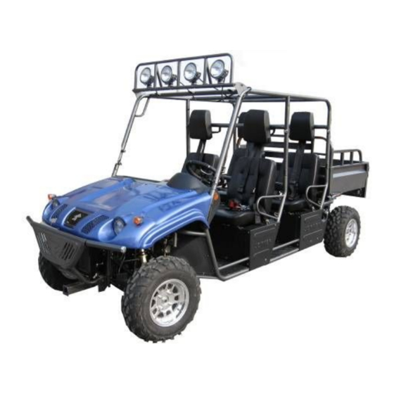
- Page 1 Owner’s manual Parts manual JNSZ650UV4S...
- Page 2 Thank you for choosing JOYNER JNSZ650UV4S. It represents the result of many years of JOYNER experience in the production of utility vehicles. With the purchase of this JOYNER, you can now appreciate the high degree of craftsmanship and reliability that have made JOYNER a leader in this field .This manual will provide you with a good basic...
-
Page 3: Table Of Contents
CONTENTS WARRANTY POLICY ..........................5 LOCATION OF THE WARNING AND SPECIFICATION LABELS .........16 SAFETY INFORMATION ........................19 CONTROL FUNCTIONS........................21 ............................21 AIN SWITCH ......................22 ULTI FUNCTION METER UNIT ............................22 WITCHES ..............................23 EDAL ........................24 ARKING BRAKE LEVER ..........................25 RIVE SELECT LEVER ...........................25 UEL TANK CAP ........................25 EATS AND AFETY BELTS... - Page 4 HEEL LIGNMENT THE USING,MAINTENANCE AND REPAIR OF THE FRONT/REAR REDUCER....66 PERIODIC MAINTENANCE......................69 WIRING DIAGRAM ...........................71 JNSZ650UV4S LIMITIED WARRANTY..................72 PARTS MANUAL ..........................73 1 CYLINDER BLOCK PART......................73 2 SPROCKET COVER AND OIL PAN PART ..................76 3 CYLINDER HEAD PART ......................78 4 PISTON ,CONNETING ROD AND CRANKSHAFT PART............82 5 BALANCING SHAFT PART ......................84...
- Page 5 19 R .............................107 OLL BAR 20 F ................108 RONT PROTECT BAR AND ELECTRICAL WINCH 21 C ..........................110 ARGO BED 23 D ........................... 114 RIVEN SYSTEM (F ) ...............121 24 F RONT MAIN REDUCER RONT DIFFERENTIAL 25 R ........................126 EAR MAIN REDUCER 26 F ......................131 RONT SUSPENSION SYSTEM...
-
Page 6: Warranty Policy
Warranty policy... -
Page 17: Location Of The Warning And Specification Labels
Read and understand all of the labels on your vehicle. They contain important information for safe and proper operation of your vehicle. Never remove any labels from your vehicle. If a label becomes difficult to read or comes off, a replacement label is available from your Joyner dealer. WARNING WARNING... - Page 18 Keep weight in the cargo bed centered,and as low an far forward as possible. Top-heavy loads increase the risk of overturn. S650.09.04.00.04(1) JOYNER WARNING Improperly loading a trailer and failure to use extra care 3.9INCH when pulling trailer can (100MM) cause an accident or injury.
- Page 19 JOYNER S650.09.04.00.11(3) TYPE: MANUFACTURER: JOYNER CHINA MAX . LOAD: VIN/NIV: JOYNER S650.09.04.00.12(1)
-
Page 20: Safety Information
Note: WARNING The enclosure cannot protect occupants in all foreseeable accidents,including rollover. JOYNER S650.09.04.00.01(2) SAFETY INFORMATION THE SAFETY IS FRIST. Severe injury or death can result if you do not follow these instructions。Read this manual and all labels carefully and follow the operating procedures described: 1. - Page 21 schedules described in this manual. 11. Always keep both hands, arms, feet, and legs inside the vehicle at all times during operation. Keep your feet on the floorboard. Never hold onto the enclosure except when using the handgrip inside the enclosure. Otherwise, your hand could be injured if it is caught between the enclosure and an obstacle outside the vehicle.
-
Page 22: Control Functions
CONTROL FUNCTIONS Main switch Functions of the respective switch positions are as follows: OFF: All electrical circuits are switched off except the turning signal both the left and the right when the light switch is on. The key can be removed in this position. ON 1: All electrical circuits are supplied with power, except the ignition system and fuel system, the headlights and... -
Page 23: Multi-Function Meter Unit
damage could occur. Wait at least 5 seconds between each operation of the electric starter to let it cool. - Do not turn the key to the "START" position with the engine running, or damage to the electric starter can result. - See starting instructions prior to starting the engine. -
Page 24: Pedal
This indicator light comes on when the drive select lever is “R” reverse position. Electricizing of the battery indicator light This indicator light comes on when the generator of the engine can’t electricize the battery. You should check the generator and battery or get help from your JOYNER dealer . Spot light switch Set the switch to turn on the spot lights. -
Page 25: Parking Brake Lever
If anyone of them can’t work well, please correct the problem .before operating the engine .If you can’t find or solve the problem yourself, please get the help from your JOYNER dealer. Parking brake lever Pull the parking lever up so that the unit can engage park brake. To release the unit, press button in the front end of parking lever then push the parking lever to the bottom. -
Page 26: Drive Select Lever
Drive select lever The drive select lever is used to shift your vehicle into the 1,2,3,4 and reverse positions. l Never start the vehicle at 3 or 4 lever. l Stop the vehicle fully when shifting to reverse. l When reversing, the reverse indicator “R” comes on and there is warning voice. -
Page 27: Glove Compartment
the seats can be Lifted just like the cargo bed . It is very easy to install or uninstall the seats, see the table of the content“seat and safety belt” 。 Safety belts This vehicle is equipped with three-point seat belts for both the operator and passenger. Always wear the seat belt while riding in the vehicle. -
Page 28: Are You Ready To Drive
Cargo bed 1. Confirm the air spring well worked. 2. Adjust the rubber bumpers to proper position, then tighten the adjust nuts . 3. Pull up the release lever on the both side of the vehicle, and then lift up the cargo bed slowly until it stops 4. -
Page 29: Protective Apparel
Protective Apparel For your safety, we strongly recommend that you always wear an approved motorcycle helmet, eye protection, boots, gloves, long pants, and long-sleeved shirt or jacket whenever you drive. Although complete protection is not possible, wearing proper gear can reduce the chance of injury when you drive. -
Page 30: Age Recommendation
handles. Practice driving the UV650-4S in a safe area to build your skills. Do not drive in rough terrain until you get accustomed to the UV650-4S’s controls, and feel comfortable with its size and weight. Operating UV650-4S without proper instruction could increase your risk of an accident which could lead to serious injury or death. -
Page 31: Is Your Vehicle Ready To Drive
Operating this UV650-4S after consuming alcohol or drugs can seriously affect your judgment, cause you to react more slowly, affect your balance and perception, and could result in serious injury or death. Never consume alcohol or drugs before or while operating this UV650-4S. IS YOUR VEHICLE READY TO DRIVE Before each drive, it is important to inspect your UV650-4S and make sure any problems you find are corrected. - Page 32 Engine Oil ■ Check the level and add oil if needed. Check for leaks. Coolant ■ Check the coolant and add coolant if needed. Check for the leaks. Fuel ■ Check the level and add fuel if needed. Also make sure the fuel cap is securely fastened.
-
Page 33: Safe Driving Precautions
Cable ■ Check the cable housing for wear. Check the fittings are tight. Replace or tighten as needed. Tie rod ■ Check the tie rod housing for wear. Check the fittings are tight. Replace or tighten as needed SAFE DRIVING PRECAUTIONS Off-Road Use Only Your UV650-4S and its tires are designed and manufactured for off-road use only, not for pavement. -
Page 34: Keep Hands And Feet On Controls
you, which could lead to a collision. In many states it is illegal to operate UV650-4S on public streets, roads and highways. Operating this UV650-4S on public streets, roads or highways can cause collision with other vehicle. Never operate this UV650-4S on any public streets, roads or highways, even a dirt or gravel one. -
Page 35: Do Not Perform Stunts
Operating this UV650-4S at excessive speeds increases your changes of losing control of the UV650-4S, which can result in an accident. Always drive at a speed that is proper for your UV650-4S, the terrain, visibility and other operating conditions, and your experience. Take Care on Unfamiliar or Rough Terrain Before driving in a new area, always check the terrain thoroughly. -
Page 36: Specifications
Attempting wheelies and other stunts increases the chance of an accident, including an overturn. Never attempt stunts, such as wheelies or jumps. Don’t try to show off. SPECIFICATIONS Model JNSZ650UV4S Dimensions: Overall length 2980mm Overall width 1435mm Overall height 1820mm... - Page 37 Electric starter Starting system Wet sumb Lubrication system Engine ail Type >0℃ SE15W/40, <0℃ SE15W/30 Recommended engine ail classification Quantity: 2.9L With oil filter cartridge replacement Final gear case oil: Type SAE85 API GL-5 hypoid gear oil Quantity 0.7L Radiator capacity(including 1.4L routes):...
- Page 38 Tire (option) Type Tubeless Size front 27 inch rear 27 inch Brakes: System Front and rear unified Type front Dual disc brake rear Dual disc brake Operation Foot operation Suspension: Front suspension Double wishbone Rear suspension Double wishbone Shock absorber: Front shock absorber Coil spring/oil damper Rear shack absorber...
-
Page 39: Operation
OPERATION Operation controls Do not attempt to start or operate the engine until completely familiar with the location and use of each control necessary to operate this vehicle. The operator must know how to stop this machine before starting and driving it. -
Page 40: Brake
Accelerator pedal Clutch pedal brake pedal Throttle Figure 3 The right foot pedal is the throttle that controls the UV650-4S speed. To disengage the clutch at any time, allow the throttle to return to the idle position. (See Fig. 3) Each time prior to starting the engine, check the throttle assembly to ensure that when pedal is pushed all the way the assembly is working smoothly and returns to idle when released. -
Page 41: Start Engine
Improper operation of the clutch will lead to excessive wear of the clutch friction surface. Note: When operate the vehicle, if it does not feel comfortable about one of the three pedals , adjust the bolt and then tighten the nut until it feels very comfortable. -
Page 42: Engine Stop Key
Each time prior to starting the engine, check the throttle assembly to ensure that when pedal is pushed all the way forward the assembly is working smoothly and returns to idle when released. Do not operate if pedal or engine throttle linkage fail to return to idle. If unable to correct the problem through lubrication, adjustment or replacement of worn parts, contact your dealer for assistance. -
Page 43: Passenger
Perform this pre-drive inspection everyday before driving vehicle. If not performed, serious damage to the vehicle or personal injury may result. 1. Check for Engine Oil Level. Check for transmission Oil Level. Check for leaks, add oil if required. 2. Check the coolant. Check for leaks, add the coolant if required. 3. -
Page 44: Seat Adjustment
Seat Adjustment The left seat can remove, but the right can’t. To move a seat, pull its seat lock lever upward, lift the front of the seat, and then slide the seat forward and up. To repair the engine and the battery conveniently, the seats can be Lifted just like the cargo bed . -
Page 45: Gear Shift Adjustment
- Pull the park brake lever up so that the unit can engage park brake. - To release the unit, press button on front end of parking lever then push the parking lever to the bottom. - Adjust the parking cable if necessary. Gear Shift Adjustment Before operate the vehicle, check the shift lever as to change gearshift from 1 to 4 and... -
Page 46: Service Instruction
- To prevent vehicle from rolling over, be sure to only turn the vehicle at a slow more controllable speed. SERVICE INSTRUCTION Service Air Cleaner Service air cleaner every 80 hours NOTE: Service more often under dusty conditions. Remove cleaner cover by bolt b. -
Page 47: Transmission Lubrication
a. With the engine warm, put the vehicle on the level ground. b. Shut down the engine, put a collecting oil plate under the engine oil outlet. Loosen the oil outlet plug in the warm engine. Let the engine oil out fully c. -
Page 48: Engine Coolant
b. Remove the iron dust plug, this plug has a magnet on it. Iron dust caused by moving parts will stick to the plug. Clean the iron dust from this dust plug. d. Tighten the transmission oil outlet plug and the iron dust plug. e. - Page 49 If the coolant in the reserve tank is less than 2/5, it needs to be topped up. 1. Turn the reserve coolant case cap counterclockwise and open the cap. 2. Pour fresh coolant of the specified type into the reserve coolant tank till the coolant reaches 2/5 to 3/5 of the reserve coolant tank volume.
-
Page 50: Spark Plug
Spark Plug Remove the spark plug and inspect it each time you change the oil. (Use a spark plug wrench) The electrodes should be kept clean and free of carbon. The presence of carbon or excess oil will greatly reduce proper engine performance. If possible, check the spark plug gap (area between electrodes) using a wire feeler gauge. -
Page 51: Repair
REPAIR Front Wheel Replacement Do not disassemble the center castle nuts when you replace the front wheels.(See Fig. 20) Tighten the nuts after replacing the wheels. Rear Wheel Replacement Do not disassemble the center castle nuts when you replace the rear wheels. Tighten the nuts after replacing the wheels. -
Page 52: Clutch Replacement
Clutch replacement Do not remove the whole engine from vehicle when you replace the clutch, but you’ll need to remove rear suspension, driven shaft, clutch cable, muffler, wires and rubber cushion that is in the middle of transmission and frame. Remove bolt M14 2. - Page 53 3. Remove two nuts (M14) on two side of transmission 4.Remove two bolts(M8) on the low mud plate of transmission 5.Remove the mud plate.
- Page 54 6.Remove the transmission 7.Remove upper mud plate 8.Insert a shaft into the hole. Remove six bolts on the pressing plate of clutch...
- Page 55 9.Remove the pressure plate. Remove the friction disc of clutch 10. Insert a special shaft into the hole, fix new friction plate on the flywheel of engine.
-
Page 56: Timing Setup And Balancing Shaft Setup
11.Fix pressure plate of clutch. Two bolts with “Y.G” mark must be inserted into two anchor hole. Tighten six bolts with torque 30 N•m . Torque 30 N•m 12. Fix upper mud plate 13. Fix parts according to reverse operation to the disassembly. Timing setup and balancing shaft setup 1. - Page 57 Camshaft timing sprocket wheel...
- Page 58 Mark Left balancing shaft Right balancing shaft sprocket sprocket Crank shaft Figure 1 Mark here Mark Left balancing shaft sprocket Figure 2...
-
Page 59: Water Pump Disassembly
Make Mark 30mm above the bolt Mark 30mm Left balancing shaft sprocket Figure 3 Water pump disassembly 1. Take off fan belt and loosen 4 bolt tightening water pump pulley. Fan belt Bolt Water pump pulley... - Page 60 Figure 4 2. Loosen the 6 bolts shown as the Figure 5. Bolts Bolts Figure 5 3. Loosen the clamp bolts shown as Figure 6, and disconnect two peace of water pipe, and take off the water pump. The engine without water pump is shown as Figure 6.
- Page 61 Clamp Bolts Water pipes Figure 6 Figure 7 1. Fix the timing chain on the sprocket of crankshaft. Mark on the sprocket of crankshaft must be in the middle of double white links of timing chain.
-
Page 62: Distributor Replacement
2. Fix the guide plate.。 3. Fix the tensional plate. 3. Fix the sprocket. Mark on the sprocket must be in straight line to the single white link on the timing chain Distributor replacement 1. turn around the crank shaft, direct the line on the pulley of crankshaft straight to the 0 degree line on the cover of engine... - Page 63 2. Remove the rocker cover of head by removing two bolts 3. Check the anchor hole, if it is not on the direction shown by Fig. Repeat above 1 as to obtain the hole direction shown by Fig.
- Page 64 4. Insert the screwdriver into the hole, turn the drive of oil pump shaft until parallel to the crankshaft 5. Align the mark 2 on the shaft of distributor to the mark 1 on the aluminum housing. 6.. Insert the distributor slowly to the hole. Confirm the direction of distributor is as per the figure.
- Page 65 7.Fix the cover of the distributor. 8. Check the spark timing. Adjust if need as followings: Loosen the nut of the distributor housing. Turn the distributor slowly. Increase the spark timing by counterclockwise turn. Decrease the spark timing by clockwise turn.
-
Page 66: Front Wheel Alignment
Front Wheel Alignment a. Put the vehicle on level ground. b. The “toe-in” of the front wheels should be 1.18 inches. To check for alignment, measure distance A and B between the centerline (CL) of the wheels. The proper toe-in dimension A should be 1.18 inches greater than dimension B. d. -
Page 67: The Using,Maintenance And Repair Of The Front/Rear Reducer
The USING,MAINTENANCE AND REPAIR OF THE FRONT/REAR REDUCER Before install the front/rear main reducer to the vehicle, we have done accurate test to each one, and don’t open them in normal. But please do the following. 1. Change the oil of the front/rear main reducer after 300Km for the first using of your vehicle. - Page 68 b. Dismantle the bolt M6(PIC.01)/M8(PIC.02) from the main case of front/rear main reducer , then let the old oil vented out . c. Before adding the new oil ,please screw the bolt M6(PIC.01)/M8(PIC.02) properly. d. Dismantle the bolt “4”and washer “3”(PIC.03),then add the new oil (GL-5,85W-90) and it is about 400-450 mL .
- Page 69 5. If it is too high about the temperature of the oil in the reducer, please stop using the vehicle and get help from your JOYNER dealer. 6. For some special reasons, you have to dismantle the drive halfshaft or change a new one , please do the following: a.
-
Page 70: Periodic Maintenance
After assembling, you must make sure that the halfshaft can’t be pulled out by hand. The front and rear main reducer are important parts to the vehicle .If you have some problems which you can’t resolve by yourself, please get help from your JOYNER dealer. PERIODIC MAINTENANCE The maintenance intervals in the following table are based upon average driving conditions. - Page 71 2. Tighten bolts on engine. 3. Engine oil 4. Coolant 5. Coolant hose and joints 6. Exhaust 7. Transmission oil Ignition 8. Coil 9. Distributor for ignition 10. Air cleaner 11. Throttle cable and choke I.A.L I.R.A Fuel tank cover. Breathe hose and joint. 13.
-
Page 72: Wiring Diagram
WIRING DIAGRAM... -
Page 73: Jnsz650Uv4S Limitied Warranty
Should warranty service be required on your JNSZ650UV4S during the 90 days warranty period, please contact your nearest authorized dealer for repairs. What is not covered under this warranty This warranty does not cover any seller vehicle that has been subjected to: a. -
Page 74: Parts Manual
PARTS MANUAL 1 CYLINDER BLOCK PART Code name Description 270Q-02009 oil feed plug Cylinder head locating dowel LJ462Q-1-1000028D Plug φ10.5×7 QTB55 freeze plug φ40 QTB54 Pinφ6×18 GB/T119-1986 freeze plug φ30 QTB542... - Page 75 1 CYLINDER BLOCK PART Code name Description 270Q-02013 Tie-in pipe of drive valve QTB28 Hexagon-headed taper bolt NPT1/4 Hollow-swage locating pin φ11×12 QTB42 270Q-02004 Jetting pipe 270Q-02003 Front bearing of balancing shaft 270Q-02011 Rear bearing of balancing shaft QTB54 Calathiform plug 8×9 Main bearing cap bolt 270Q-02102 QTB53A...
- Page 76 1 CYLINDER BLOCK PART Code name Description 270Q-02008 Rear oil seal housing gasket Rear oil seal housing 270Q-02007A Flywheel bolt LJ462Q-1-1000082D 270Q-04007 Crankshaft bearing bushing 270Q-04008 Crankshaft thrust bearing bushing 270Q-02006C Oil pressure switch Cylinder block and bearing cap assembly 276Q-0210D Hollow-swage locating pin φ13×15.5 QTB42...
-
Page 77: Sprocket Cover And Oil Pan Part
2 SPROCKET COVER AND OIL PAN PART Code name Description 276Q-02201 Sprocket cover 270Q-02202 Oil filter threaded sleeve GB/T900-88 Taper bolt AGM8-M8×22-8.8 QTB23 Hexagon-headed taper bolt NTP1/4 QTB23 Hexagon-headed taper bolt NTP3/8 270Q-02004 Jetting pipe LJ276MT-2-02400 Dipstick -2001 Left gasket of sprocket cover -2002 Right gasket of sprocket cover QTB10... - Page 78 2 SPROCKET COVER AND OIL PAN PART Code name Description QTB53A Crankshaft front oil seal with unidirectional flow around FB35×50×8 QTB10 Hexagon-headed bolt with edge M8×78 Oil Pan gasket 270-02005A LJ276MT-2-02300 Oil Pan assembly GB/T9074.17-1988 Bolt assembly M6×12 QTB24 Drain Plug M14×1.5 Drain Plug gasket 270Q-02303B backing plate...
-
Page 79: Cylinder Head Part
3 CYLINDER HEAD PART Code name Description GB/T5782-1986 Bolt M8×40 270Q-01009 washer of cylinder head cover bolt Rubber pad of cylinder head cover bolt 270Q-01011 Cylinder head cover assembly 276Q-01300 270Q-01400B Filler cap assembly 270Q-01403 Filler cap rubber washer 270Q-01012B Seal ring of cylinder head cover GB/T9074.17-1988 Unit bolt M8×30... - Page 80 3 CYLINDER HEAD PART Code name Description 270Q-01017 Thermostat housing Thermostat gasket 270Q-01016 Thermostat 270Q-01015 270Q-01100 Cylinder head and camshaft bearing part 270Q-01109 Camshaft bearing bushing cap bolt 270Q-01007 Valve rocker arm shaft GB/T898-1988 Stud AGM8×25-8.8 GB/T899-88 Stud AGM8×28-8.8 270Q-01104 Inlet valve guide Locating pin φ...
- Page 81 3 CYLINDER HEAD PART Code name Description 270Q-01105 Exhaust valve guide GB/T899-88 bolt Hexagon -headed taper plug 270Q-01023A GB/T898-1988 Stud AGM8-M8×20-8.8 270Q-01018 Minor water pipe 270Q-01102 Intake valve seat Exhaust valve seat 270Q-01103B Water Temperature sender unit 270Q-01019B 270Q-01013 Front Semi-Circle Oil Seal 270Q-01014 Rear Semi-Circle Oil Seal...
- Page 82 3 CYLINDER HEAD PART Code name Description Cylinder head bolt 270Q-01022 head bolt washer φ21×φ11×3 GTB30 GB/T9074.17-1988 Bolt assembly M8×28 276Q-01021 Cylinder head gasket 270Q-01025 Rubber blanking plug ZB/TT32005.1-88 hose clamp 270Q-01024 Exhaust pipe gasket GB/T93-1987 Washer8 QTB15 Nut M8-8...
-
Page 83: Piston ,Conneting Rod And Crankshaft Part
4 PISTON ,CONNETING ROD AND CRANKSHAFT PART Code name Description 276Q-03002 Piston ring (1) 276Q-03003 Piston ring (2) 276Q-03200 Piston ring (3) Connecting rod bearing 270Q-03006 276Q-03001 Piston 276Q-03004B Piston Pin 270Q-03100 Connecting rod assembly(1) Connecting rod assembly(2) Connecting rod bolt 270Q-03103 Connecting rod nut 270Q-03104... - Page 84 4 PISTON ,CONNETING ROD AND CRANKSHAFT PART Code name Description GB/T859-1987 Spring washer 12 Washer 270Q-04002 Crankshaft belt pulley 270Q-04003 270Q-04004A Driven bevel gear QTB44 Woodruff key4×19 276Q-04006B Crankshaft LJ462Q1-1000135D Locating pin of fly wheel Ring gear assembly of fly wheel LJ368-1005011 LJ462Q-1-1005014D Flywheel bolt...
-
Page 85: Balancing Shaft Part
5 BALANCING SHAFT PART Code name Description Thick washer φ24×φ8.5×3 QTB30 270Q-04400 Balancing chain assembly 270Q-04310A Balancing shaft sprocket assembly QTB10 Hexagon-headed bolt with edge M6×10 Baffle plate of Balancing shaft 270Q-04301 270Q-04302A Balancing shaft 270Q-04303 Front balancing weight 270Q-04305 Balancing weight bolt 270Q-04304 Rear balancing weight... -
Page 86: Camshaft And Chain Train Part
6 CAMSHAFT AND CHAIN TRAIN PART Code name Description Bolt assembly 270Q-05400 270Q-05007 Washer 270Q-05005A Tensioning spring 270Q-05004 Tensioning spring plate QTB13 Small hexagon-headed bolt with edge M12×1.25×30 Camshaft timing sprocket wheel 270Q-05002A 270Q-05100 Timing chain assembly 270Q-01502 Valve clearance adjusting nut 270Q-01501 Valve clearance adjusting bolt 270Q-01004... - Page 87 6 CAMSHAFT AND CHAIN TRAIN PART Code name Description 276Q-01002A Valve spring 270Q-01005A Intake Valve 270Q-01001 Lower seat of valve spring Wave form washer 270Q-01008 270Q-01510 Valve rocker arm of first cylinder 270Q-01610 Valve rocker arm of second cylinder 270Q-01006 Exhaust Valve QTB13 Small hexagon-headed bolt with edge...
-
Page 88: Intake Manifold Part
7 INTAKE MANIFOLD PART Code name Description 270Q-06006 Intake manifold paper gasket LJ276MT-2-06000 Intake manifold GB/T898-1988 Stud AC-M8×25-8.8 GB/T848-1985 Stud AC-M8×28-8.8 QTB77 Flat washer Spring washer φ8 GB/T93-1978 QTB15 Nut M8-8 QTB26 Clip GB/T899-1988 Square head taper plug Z 3/8″... -
Page 89: Oil Filter And Oil Pump Part
8 OIL FILTER AND OIL PUMP PART Code name Description 270Q-17000 Oil Filter assembly GB/T9074.17-1988 Bolt assembly M6×48 LJ276MT-2-16000 Oil pump subassembly GB/T9074.17-1988 Bolt assembly M6×53... -
Page 90: Water Pump And Fan Part
9 WATER PUMP AND FAN PART Code name Description ZB/TT32005.1-88 Hose clamp Rubber pipe (2) 270Q-19011 270Q-19013 water pump pulley QTB10 Hexagon-headed bolt with edge M8×88 GB/T9074.15-1988 Hexagon head bolt M6×20 QTB32 Washer 7.5 Fan assembly 276Q-19200 QTB93A Fan belt AV10×845 QTB10 Hexagon-headed bolt with edge M8×23 270Q-19002B... -
Page 91: Distributor And Its Line Unit
10 DISTRIBUTOR AND ITS LINE UNIT Code name Description 270Q-23510W Distributor assembly(non contact) FDQ-60000 Rotor assembly F6RTC Spark plug(damping) FDQ-1-50000 Distributor cap assembly 270Q-23901 Distributor protective cover LJ276MT-2-23501 Vacuum rubber tube ZN410-163A High – tension leads(anti-jamming) Ignition coil assembly LJ462Q-1-3705010DW... -
Page 92: Carburetor Part
11 CARBURETOR PART Code name Description 270Q-06004 Carburetor gasket 270Q-06003 Carburetor insulator Carburetor assembly (blue marked) 276Q-13000-2 JB12D-H Electric petrol pump... -
Page 93: Air Filter And Pipe Line Part
12 AIR FILTER AND PIPE LINE PART Code name Description LJ276MT-2-07100F Air filter housing QK1706-03 Flexible hose clamp LJ276MT-2-07001F Flexible intake hose LJ276MT-2-07002F Rubber breathing pipe 270Q-07003 Storing dust pipes QK1706-05 air filter(marked) -
Page 94: Starter , Alternator And Their Fastening Piece
13 STARTER , ALTERNATOR AND THEIR FASTENING PIECE Code name Description Starter assembly LJ368Q-3708010 LJ368Q-1000068 Starter clamp bolt QTB15 Hexagon nut M8-8 Spring washer 8 GB/T93-1987 270Q-02203A Adjusting bolt GB/T9074.15-1988 Bolt assembly M8×25 Thick washerφ24×φ8.5×3 QTB30 270Q-25010A Alternator bracket 270Q-25001 Second fixed swift First fixed swift (insert) 270Q-25020... -
Page 95: Transmission Tank
14 TRANSMISSION TANK Code name Description 1701111 Upper housing of transmission 1701112 Lower housing of transmission 1701113 Locating pin GBT5787—86 Bolt M6×40 GBT5787—86 Bolt M8×50 GBT5787—86 Bolt M8×70 GBT5787—86 Bolt M8×90 GBT5787—86 Bolt M8×135 1701301 Baffle plate of seal ring of the first shaft GB3452.1—82 “O”... - Page 96 14 TRANSMISSION TANK Code name Description 1701140 Dip stick assembly GB3452.1—82 “O” type seal ring15×2.65 ZBT32001.3—87 Bolt Z 1/2″—14 ZBT32001.9—87 Bolt Z 1/2″—14( magnetism ) 1701017 Sight hole cover 1702050 Sealing cover assembly of shift lever 1701025 Breathing pipe tie-in 1701026 Breathing pipe 1701023...
- Page 97 14 TRANSMISSION TANK Code name Description 3729010 Reverse switch GB3452.1—82 “O” type seal ring15×2.65 1000013 Supporting piece 1701024 Line fastener LJ368Q—1000163 Shouldered tap bolt LJ368Q—1000169 Shouldered tap bolt LJ368Q—1000167 Stud GB/T6171—1986 Nut M10×1.25 GB/T848—1985 Washer10 4T06C Transmission assembly...
-
Page 98: Clutch, Shifter Shaft And Rocker Arm
15 CLUTCH, SHIFTER SHAFT AND ROCKER ARM Code name Description QST160HH14 Clutch pressure plate Clutch cover bolt LJ462Q—1—1005024D GB/T9074.15—1988 Bolt tab M8×16 GB859—87 Light gage spring washer8 DST160A71 Clutch plate 1701510 Clutch release bearing 1701501 Release bearing carrier 1701022 Circlip 1701040 Clutch fork 1701019... -
Page 99: First Shaft And Countershaft
16 FIRST SHAFT AND COUNTERSHAFT Code name Description 1701130 The first shaft assembly GB/T276—94 Endocentric ball bearing 6204—2RS/P53 1701310 The first shaft seal ring assembly GB/T276—94 Endocentric ball bearing 6204—2RS/P53 1701011 Thrust ring of the first shaft bearing 1701120 The first shaft seal cap assembly 1701201 Countershaft 1701250... - Page 100 16 FIRST SHAFT AND COUNTERSHAFT Code name Description 1701012 Thrust ring of countershaft bearing (left) 1701219 Tight nut of countershaft 1701050 Sealing cap assembly of Countershaft (left) 1701211 The first gear of countershaft GB309—84 Needle P2×7.8 1701203 The first gear gasket of countershaft GB308—84 Steel ball4.7625G60b 1701204...
- Page 101 16 FIRST SHAFT AND COUNTERSHAFT Code name Description 1701012 The second and the third gears bushing ring GB5846—86 Needle bearing K303520 1701206 The second and the third gears gasket 1701208 The third gear spacer 1701207 The second and the third gears pressure spring 1701214 Fourth gear of countershaft GB5846—86...
- Page 102 16 FIRST SHAFT AND COUNTERSHAFT Code name Description 1701217 Low synchronizer ring spring 1701216 Low synchronizer ring (right) 1701233 Low synchronizer spring 1701234 Synchronizer guide block 1701242 High synchronizer shell 1701241 High synchronizer sleeve 1701218 High synchronizer ring 1701243 High synchronizer spring 1701234 Synchronizer guide block 1701080...
- Page 103 16 FIRST SHAFT AND COUNTERSHAFT Code name Description GB119—86 Pin D5×13 1701070 Sealing cap assembly of reverse gear shaft 1701202 Speed gage worm 1701209 Speed gage worm wheel 1701401 Speed gage worm wheel bushing ring GB3452.1—82 “O” type seal ring 1701410 Seal ring assembly of Speed gage worm wheel 1701028...
-
Page 104: Gear Shifted Gear Fork
17 GEAR SHIFTED GEAR FORK Code name Description 1702014 Shift fork for the first gear 1702017 Shift fork for the first and the second gears 1702015 Shift fork for the third and the fourth gears 1702012 Reverse gear shift fork 1702011 Reverse gear shift cantilever 1702060... - Page 105 17 GEAR SHIFTED GEAR FORK Code name Description GB879—86 Pin 4.5×18 GB879—86 Pin 4.5×20 GB309—84 Needle 3×9.8 GB308—84 Steel ball 9.5250G60b 1701021 Hole plug GB308—84 Steel ball9.5250G60b 1702021 Locating spring of high and low speed shift level 1702022 Locating spring 1702082 Transposition Rocker arm 1702081...
- Page 106 17 GEAR SHIFTED GEAR FORK Code name Description Steel ball 7.9375G60b GB308—84 Locating spring 1702029 Transposition shaft washer 1702026 Long spring of Transposition shaft 1702024 Short spring of Transposition shaft 1702025 Shift shaft assembly 1702070 Transposition shaft rocker 1702028 Pin 5×22 GB879—76 Seal ring assembly of shift shaft 1702040...
-
Page 107: Frame
18 Frame Part No. Part Description Comments S650.01.01.00.00-4S Main frame GB/T6177.1-2000 Flange nut M10*1.25 GB/T5787-1986 Flange bolt M10*1.25*25 S650.01.01.06.00 Mount of the right seat GB/T70.1-2000 Socket head screw M10*1.25*25 S650.01.02.05.00 Lower roll bar,rear S650.01.02.05.00-4S Lower roll bar,front... -
Page 108: Roll Bar
19 Roll bar Part No. Part Description Comments GB/T70.1-2000 Socket head screw M10*1.25*25 S650.01.02.03.00 Up roll bar, front S650.01.02.02.00-4S Right roll bar S650.01.02.06.00 Up roll bar, rear S650.01.02.04.00 Roll bar for head, rear S650.01.02.01.00-4S Left roll bar S650.01.02.04.00-4S Roll bar for head, front S650.01.02.07.00-4S Straight roll bar, left S650.01.02.08.00-4S... -
Page 109: Front Protect Bar And Electrical Winch
20 Front protect bar and electrical winch Part No. Part Description Comments S650.01.03.00.01 Decorative cover S650.01.03.01.00 Front protect bar GB/T5787-1986 Flange bolt M10*1.25*25 GB/T6177.1-2000 Flange nut M10*1.25 GB/T882 Pivot pin 10*70 GB/T95 Flat washer Ø10 GB/T91-2000 Cotter pin Ø3.2*30... - Page 110 20 Front protect bar and electrical winch Part No. Part Description Comments GB/T6177.1-2000 Nut self-lock M8 GB/T96-1987 Spring washer Ø8 GB/T95 Flat washer Ø8 S650.06.12.02.00 Wire cable guide S650.01.05.00.00 Mount of electrical winch GB/T5787-1986 Flange bolt M8*25 S650.06.12.01.00 Electrical winch...
-
Page 111: Cargo Bed
21 Cargo bed Part No. Part Description Comments S650.01.04.00.00 Cargo bed GB/T6177.1-2000 Flange nut M10*1.25 S650.02.03.02.00 Rubber bumper GB/T882 Pivot pin 8*30 S650.02.03.01.00 Air spring GB/T95 Flat washer Ø8 GB/T91-2000 Cotter pin Ø3.2*30 GB/T882 Pivot pin 10*70 GB/T95 Flat washer Ø10 S650.09.01.07.00 Release lever GB/T6177.1-2000... - Page 112 22 Engine and muffler mount assy 26 27 Part No. Part Description Comments S650.04.01.05.00-4S Choke cable S650.04.01.03.00 Engine mount ,Right GB/T95 Flat washer Ø10(11*20*2) GB/T96-1987 Spring washer Ø10 GB/T5787-1986 Flange bolt M10*1.25*25 D650.04.01.00.01 Engine rubber bumper GB/T6177.1-2000 Flange nut M10*1.25 S650.04.01.00.00 Engine (LJ276M) S650.04.01.02.00...
- Page 113 22 Engine and muffler mount assy 26 27 Part No. Part Description Qty Comments S650.04.04.03.00A Mount ,exhaust pipe S650.04.04.01.00B Muffler D650.04.04.00.09 Carbon bush GB/T5787-1986 Flange bolt M8*35 GB/T6177.1-2000 Nut, self-lock M6 S650.04.04.03.01 Heat insulation guard S650.04.04.02.00A Exhaust pipe 270Q-06006 Exhaust gasket ,engine GB/T6173-2000 Nut M8 D650.04.04.00.06...
- Page 114 22 Engine and muffler mount assy 26 27 Part No. Part Description Qty Comments E650.04.04.00.12 clamp JD0820004 Air-inlet pipe E650.04.04.04.00 Air filter E650.04.04.00.10 Air filter hoop GB/T5787-1986 Flange bolt M6*20 GB/T6177.1-2000 Nut, self-lock M6...
-
Page 115: Driven System
23 Driven system Part No. Part Description Comments GB/T5787-1986 Flange bolt M10*35 S650.03.01.00.04 Stub axle ,FL D650.03.01.00.06 Seal 40*58*7*5 S650.03.01.02.00 Propellers shaft ,FL 5~23 GB/T91-2000 Cotter pin 4*40 S650.03.01.02.01 Nut M18*1.5 S650.03.01.02.02 Bell type housing S650.03.01.02.03 Circlip S650.03.01.02.04 Seal retainer,bigger S650.03.01.02.05 Boot S650.03.01.02.06... - Page 116 23 Driven system Part No. Part Description Comments S650.03.01.02.07 boot GB/T893.2-1986 Circlip Ø20,external Circlip ,bigger S650.03.01.02.08 S650.03.01.02.09 Bell type housing ,FL S650.03.01.02.10 Circlip S650.03.01.02.11 Bell type housing ,FR GB/T5787-1986 Flange bolt M12*1.25*120 S650.03.01.05.00A Front main reducer GB/T6177.1-2000 Flange nut M12*1.25 S650.03.01.03.00 Propellers shaft ,FR 5~14、16、...
- Page 117 23 Driven system Part No. Part Description Comments S650.03.01.00.05 Stub axle ,FR S650.06.10.00.00 Electric locker for 2 to 4WD GB/T5787-1986 Bolt GB/T893.2-1986 Circlip Ø 30, external S650.03.03.01.00-4S Inboard slip driveshaft ,F GB/T895.2-1986 Circlip S650.04.01.01.00 Engine LJ276-M D650.03.01.00.05 Bear GB/T893.2-1986 Clrclip Ø 55, internal D650.03.01.00.04 Seal 40*55*6...
- Page 118 23 Driven system Part No. Part Description Comments GB/T5787-1986 Flange bolt M18*16 D650.03.02.00.05 Brake disc S650.03.01.00.01 Bolt M12*1.5,hub S650.03.01.00.03 Front hub S650.03.01.04.00 Wheel 25*8-12,FR 37、38 S650.03.01.04.01 Front wheel rim 12*6 S650.03.01.04.02 Front tyre S650.03.01.00.02 Nut M12*1.5, hub S650.03.01.01.00 Wheel 25*8-12,FL 37、38 S650.03.02.04.00 Wheel 25*10-12,RR...
- Page 119 23 Driven system Part No. Part Description Comments S650.03.02.04.01 Rear wheel rim 12*8 S650.03.02.00.03 Rear hub GB/T3452.1-1992 Seal FB 45*65*8 GB/T893.2-1986 Clrclip Ø 65, internal Peer Bear 35*65*35 42 、43 S650.03.02.01.00 Wheel 25*10-12 ,RR S650.03.03.02.00 Inboard slip driveshaft ,R S650.03.02.00.04 Rear shaft carrier GB/T3452.1-1992 Seal FB 42*62*8...
- Page 120 23Driven system Part No. Part Description Comments S650.03.02.00.02 Spacer GB/T5787-1986 Flange bolt M12*1.25*105 S650.03.02.25.00D Propellers shaft ,R 5、58~68 S650.03.02.03.00D Rear main reducer S650.03.02.02.01 Nut , M24*1.5 S650.03.02.02.02 Bell type housing S650.03.02.02.03 Circlip ,smaller S650.03.02.02.04 Seal retainer ,bigger S650.03.02.02.05 Boot , S650.03.02.02.06 Seal retainer ,smaller S650.03.02.02.07...
- Page 121 23 Driven system Part No. Part Description Comments S650.03.02.02.08 Circlip Ø 24 ,external GB/T893.2-1986 Circlip , external S650.03.02.02.09 Bell type housing S650.03.02.02.10 Circlip , smaller S650.03.03.03.00-4S Bearing block S650.03.03.00.01-4S Position-setting sleeve Circlip for bearing Φ40 GB/T894.2-86...
-
Page 122: Front Main Reducer(Front Differential
24 Front main reducer(Front differential) Part No. Part Description Comments GB/T70.1-2000 Hex bolt M8*40 GB/T293-1987 Spring washer Ø8 GB/T95 Flat washer Ø8 GB/T3452.1-1992 Seal FB 65*85*10 10006 Bolt 10005 Washer 10003 Seat for out 11000 Differential gear mount 33~43 10002 Main case S650.09.01.00.01 Bolt M6... - Page 123 24 Front main reducer Part No. Part Description Comments 10017 Spring 10008 Adjust washer GB/T297-1994 Bear 30206/p6 10009 Spacer 10016 Shaft of fork 10010 Washer 10011 12000 Fork mount 30、31、32 10012 Slip gear GB/T70.1-2000 Hex bolt M8*50 GB/T3452.1-1992 Seal FB 38*58*8 GB/T893.1-1986 Circlip Ø...
- Page 124 24 Front main reducer Part No. Part Description Comments GB/T296-1994 Bear 6006/P6 10001 Seat for enter 10014 Spacer 12001 Fork GB/T893.1-1986 Circlip Ø 65, external 12002 Sensitive shaft GB/T5783-2000 Bolt M8*25 GB/T292-1992 Bear 7008AV/P6 10004 Adjust washer 11001 Driven gear 11002 Thrust washer 11003...
- Page 125 24 Front main reducer Part No. Part Description Comments 11005 Adjust washer of plant gear 11007 Differential case GB/T879.1-2000 pin 5*45 11006 Pinion shaft...
- Page 126 25 Rear main reducer Part No. Part Description Comments GB/T70.1-2000 Hex bolt M8*40 GB/T96-1987 Spring washer Ø8 GB/T95 Flat washer Ø8 GB/T3452.1-1992 Seal FB 65*85*10 10006 Bolt 10005 Washer...
-
Page 127: Rear Main Reducer
25 Rear main reducer Part No. Part Description Comments 10003 Seat for out 10013 vent-plug 21000 Driven gear mount 28~32 GB/T5786-1986 Nut A M8*16 10015 washer 10002 Main case... - Page 128 25 Rear main reducer Part No. Part Description Comments 20002 Gear ,enter 10008 Adjust washer GB/T297-1994 Bear 30206/P6 10009 Spacer 10010 Washer 10011...
- Page 129 25 Rear main reducer Part No. Part Description Comments 20003 Slip gear GB/T5787-1986 Flange bolt M8*50 GB/T5787-1986 Flange bolt M8*40 GB/T3452.1-1992 Seal FB 38*58*8 GB/T893.1-1986 Circlip Ø 55 , internal GB/T296-1994 Bear 6006/P6...
- Page 130 25 Rear main reducer Part No. Part Description Comments GB/T296-1994 Bear 6006/P6-RS 20001 Seat for enter 10014 Spacer GB/T5783-2000 Bolt M8*25 GB/T292-1992 Bear 7008AV 10014 Adjust washer...
- Page 131 25 Rear main reducer Part No. Part Description Comments 21001 driven gear 21002 joint shaft of driven gear...
-
Page 132: Front Suspension System
26 Front suspension system Part No. Part Description Comments GB/T5787-2000 flange bolt M12*1.5*85 Seal Ø54 S650.02.01.00.03 S650.02.01.00.01 Bear S650.02.01.00.02 Spacer GB/T1152 blowhole M8 GB/T6177.1-2000 flange nut M12*1.5 S650.02.01.03.00 Suspension arm ,upper , FL GB/T5787-2000 flange bolt M12*1.5*60 Circlip Ø34 ,external GB/T894.2-1986 S650.02.01.01.00 Ball joint... -
Page 133: Rear Suspension System
27 Rear suspension system Part No. Part Description Comments GB/T6177.1-2000 flange nut M12*1.5 S650.02.01.00.03 Seal Ø54 S650.02.01.00.01 Bear GB/T5787-2000 flange bolt M12*1.5*85 S650.02.01.00.02 Spacer GB/T1152 blowhole M8 S650.02.02.02.00 Suspension arm , upper , RL S650.02.02.03.00 Suspension arm , lower , RL S650.02.02.04.00 Suspension arm , lower , RR S650.02.02.05.00... -
Page 134: Gear-Shift Mechanism
28 Gear-shift mechanism Part No. Part Description Comments GB/T5787-2000 flange nut M8*50 S650.05.02.05.00 Bracket of arm of gear-shift S650.05.02.00.04 Spacer S650.05.02.06.00 Arm of gear-shift S650.05.02.00.02 Spacer S650.05.02.00.03 Nylon GB/T5787-2000 flange nut M8*25 S650.04.01.01.01 Engine gear-shift GB/T5787-2000 flange nut M8*90... - Page 135 28 Gear-shift mechanism Part No. Part Description Comments GB/T5787-2000 flange nut M10*1.25 S650.05.02.04.00 Shifter assy 12、13、14 GB/T5786-1986 Rubber GB/T5787-1986 Rubber S650.05.02.01.00 Shifter assy GB/T95 Flat washer Ø6 GB/T91-2000 Cotter pin 2.5*25 S650.05.02.03.00-4S Gear-shift cable NO.2...
- Page 136 28 Gear-shift mechanism Part No. Part Description Comments S650.05.02.02.00-4S Gear-shift cable NO.1 GB/T818-85 Bolt M6*25 GB/T6177.1-2000 Nut, self-lock M6 GB/T6177.1-2000 Flange nut M6 S650.04.01.01.00 Engine...
-
Page 137: Steering Assy
29 Steering assy 17 18 19 20 21 22 20 21 11 12 Part No. Part Description Comments GB/T818-20000 Cross bolt M6*20 DI250.03.01.00.00 Steering wheel GB/T6177.1-2000 Nut , self-lock M6 S650.05.01.01.00 Steering column assy S650.05.01.01.01 Steering wheel shaft S650.05.01.00.01 Boot S650.05.01.01.02 Steering column housing GB/T894.1-1986... - Page 138 29 Steering assy 17 18 19 20 21 22 20 21 11 12 Part No. Part Description Comments S650.05.01.02.00 Steering universal rod GB/T91-2000 Cotter pin 3.2*40 GB/T9457-1988 Slotted nut M14*1.5 S650.05.01.03.01 Joint ball GB/T6170-2000 Nut M14*1.5 S650.05.01.03.02 Steering roll GB/T6170-2000 Nut M14*1.5-L POA 14-L Joint bear ,POA M14*1.5-L...
- Page 139 29 Steering assy 17 18 19 20 21 22 20 21 11 12 Part No. Part Description Comments D650.05.01.00.06 Bigger washer D650.05.01.00.05 Smaller washer D650.05.01.00.04 Thin rubber cover D650.05.01.00.03 Thick rubber cover D650.05.01.00.02 Mounting rack GB/T5787-2000 flange bolt M10*1.25*20...
-
Page 140: Radiator Assy
30 Radiator assy Part No. Part Description Comments GB/T5787-2000 Flange bolt M6*20 D800.04.02.01.02 rubber pad D800.01.02.05.00 radiator lower mount GB/T6177.1-2000 Nut , self-lock M6 GB/T5787-2000 Flange bolt M6*12 D800.04.02.01.00 Radiator D650.04.02.00.03 Hoop (25-38), water tube S650.04.02.00.01 Water inlet hoop, engine D650.04.03.00.04 Hoop (10-16) S650.04.02.00.04... - Page 141 30 Radiator assy Part No. Part Description Comments GB/T6177.1-2000 Nut , self-lock M8 GB/T6177.1-2000 flange nut M8 S650.04.02.00.03-4S plank of hose S650.04.02.00.02 Water outlet hoop, engine D1600.04.02.00.07 Junction...
-
Page 142: Throttle And Park Braking
31 Throttle and park braking 11 12 Part No. Part Description Comments GB/T5787-1986 Flange bolt M8*20 S650.07.01.01.00-4S Four-caliper brake assy D650.07.01.00.04 Master cylinder rod GB/T6172.1-2000 Nut M8(m=6.8) S650.07.01.00.01-4S Master cylinder rod block 3.4.5 GB/T91-2000 Cotter pin 3.2*30 GB/T95 Flat washer Ø8 S650.07.04.02.00 Clutch pedal D650.07.01.00.05... - Page 143 31 Throttle and park braking 11 12 Part No. Part Description Comments GB/T882 Short pivot pin 8*75 GB/T91-2000 Cotter pin 2*25 GB/T95 Flat washer Ø6 S650.07.01.02.00 Brake pedal GB/T882 Short pivot pin 6*40 GB/T882 Short pivot pin 8*105 S650.07.03.02.00 Throttle pedal S650.07.03.01.00-4S Throttle cable GB/T6177.1-2000...
- Page 144 31 Throttle and park braking 11 12 Part No. Part Description Comments GB/T91-2000 Cotter pin 3.2*30 GB/T882 Pivot pin 6*18 S650.07.02.01.00-4S Park brake cable GB/T70.1-2000 Hex bolt M6*35 GB/T5787-1986 Flange bolt M8*30 S650.07.02.02.00 Single hydraulic assy 32、33、34 D650.07.02.03.01 Pump , single hydraulic assy D650.07.02.03.02 Oil cup, single hydraulic assy D650.07.02.03.03...
-
Page 145: Fuel Tank And Gasoline Pump
32 Fuel tank and gasoline pump Part No. Part Description Comments GB/T6177.1-2000 Flange Nut M10 S650.04.03.01.02 Fuel tank rubber strap S650.04.03.03.06 Fuel tank strap S650.04.03.01.00 Fuel tank assy 2、20~23 GB/T5787-1986 Flange bolt M8*25 GB/T6177.1-2000 Nut , self-lock M8 D650.04.03.02.00 Gasoline pump D650.04.03.00.05 Gasoline filter... - Page 146 32 Fuel tank and gasoline pump Part No. Part Description Comments S650.04.05.00.02 Oil gas segregator D650.04.05.01.00 Air filter GB/T5787-1986 Flange bolt M6*16 D650.04.06.00.02 Plank GB/T6177.1-2000 Flange Nut M6 D650.04.06.01.00 Carbon pot D800.04.03.00.01 Joint spacer D650.04.06.00.01 Plank of Carbon pot...
- Page 147 32 Fuel tank and gasoline pump Part No. Part Description Comments D650.04.06.02.00 Oil valve S650.04.03.00.10 Plank oil valve S650.04.03.01.06 Key of fuel tank S650.04.03.01.03 Cap of fuel tank S650.04.03.01.01 Fuel tank S650.04.03.01.02 Fuel level sensor unit...
-
Page 148: Seat And Safety Belt
33 Seat and safety belt Part No. Part Description Comments S650.09.01.04.00 Safety belt assy GB/T5787-1986 Flange bolt M12*1.25*30 GB/T95 Flat washer Ø12 GB/T93-1987 Spring washer Ø12 GB/T41-2000 Nut M12*1.25 GB/T5787-1986 Flange bolt M12*1.25*30 (BWD) S650.09.01.04.02 Inner buckle S650.09.01.04.01 Safety belt GB/T91-2000 Cotter pin 3.2*30 GB/T882... - Page 149 33 Seat and safety belt Part No. Part Description Comments S650.09.01.02.01 Track, Right seat S650.09.01.01.02 Track, Left seat S650.09.01.01.01 Track, Left seat S650.09.01.03.00 Headrest GB/T5787-1986 Flange bolt M8*25 S650.09.01.02.00 Right seat S650.09.01.01.00 Left seat...
-
Page 150: Electrical Appliance And Other Parts
34 Electrical appliance and other parts Part No. Part Description Comments S650.06.02.00.00 Headlight S650.06.02.02.00 Headlight cover S650.06.02.01.00 Headlight bulb S650.06.02.03.00 Spring GB/T95 Flat washer Ø5 GB/T948 Bolt M5*50 S650.06.03.00.00 turning signal, front, left GB/T6177.1-2000 Nut, self-lock M5 GB/T6177.1-2000 Nut, self-lock M8... - Page 151 34 Electrical appliance and other parts Part No. Part Description Comments GB/T5787-1986 Flange bolt M8*20 D650.06.00.09.00 Loudspeaker S650.06.06.00.00 Four switch assembly S650.06.10.00.00 Electric locker for 2 to 4 WD S650.06.07.00.00 three switch assembly S650.06.05.00.00 LCD meter unit GB/T6177.1-2000 Nut, self-lock M6 D650.06.00.13.00 Loudspeaker button D650.06.00.08.00...
- Page 152 34 Electrical appliance and other parts Part No. Part Description Comments D650.01.02.08.00 Battery bracket GB/T5787-1986 Flange bolt M8*140 D1600.06.02.00.00 Battery (36AH) D650.08.01.00.11 Rubber cover of Battery GB/T6177.1-2000 Flange nut M10*1.25 S650.06.15.00.00 Tail lamp D650.06.00.10.00 Flasher unit D650.06.00.11.00 Regulator GB/T818-2000 Cross bolt M6*16 D650.04.01.00.02 Ignition coil assemly...
- Page 153 34 Electrical appliance and other parts Part No. Part Description Comments S650.06.09.00.00 Reverse warning speaker S650.06.11.00.00 Speed sensor S650.06.01.01.00-4S Harness wiring S650.06.12.01.00 Electrical winch S650.06.12.03.00 Wire cable guide GB/T6177.1-2000 Flange nut ,M8 GB/T41-2000 Nut ,M8 S650.06.14.00.00 Express connection-peg...
- Page 154 34 Electrical appliance and other parts Part No. Part Description Comments S650.06.12.07.00 Wiring of connection-peg E650.08.01.00.07 Driving mirror ,right E650.08.01.00.08 Driving mirror ,left S650.06.13.00.00 Flasher board S650.06.04.00.00 turning signal, F,R...
-
Page 155: Plastic Parts
35 Plastic parts Part No. Part Description Comments S650.08.01.00.00 The front main baffle S650.08.00.00.01-4S Instrument panel S650.08.00.00.02-4S Baffle of Instrument panel S650.08.00.00.17 Front baffle of right seat S650.08.00.00.09 Side baffle of right-rear seat S650.08.00.00.03-4S Baffle of front inboard slip driveshaft S650.08.00.00.04-4S Baffle of shifter assy S650.08.00.00.05-4S... - Page 156 35 Plastic parts Part No. Part Description Comments S650.08.00.00.14 Baffle of right drive half-shaft S650.08.00.00.13 Baffle of left drive half-shaft S650.08.00.00.16 Cover of LCD meter unit S650.08.00.00.10 Rear baffle of right seat S650.08.00.00.06 Front baffle of left-rear seat S650.08.00.00.08 Rear baffle of left-rear seat S650.08.00.00.21-4S Middle baffle, rear S650.08.00.00.22-4S...
-
Page 157: Accessories(Option
36 Accessories(option) Part No. Part Description Comments GB/T5787-1986 Flange bolt M10*1.25*25 S650.09.05.02.00 Bracket of spot light GB/T6771.2-2000 Flange nut M12 GB/T96-1987 Spring washer Ø12 GB/T95 Flat washer Ø12 D1600.06.01.00.00 Spot light... -
Page 158: Snow Scraper( Option
37 Snow scraper( option) Part No. Part Description Comments GB/T882 Pivot pin 10*70 S650.06.12.01.00 Electrical winch GB/T5787-1986 Flange bolt M8*25 S650.09.06.03.00 Mounting of snow scraper S650.06.12.02.00 Wire cable guide GB/T882 Pivot pin 20*75 S650.09.06.04.00 Redirector GB/T882 Pivot pin 20*210... - Page 159 37 Snow scraper option) ( Part No. Part Description Comments S650.09.06.01.00 Main snow scraper S650.09.06.02.00 Minor snow scraper GB/T5787-1986 Flange bolt M10*1.25*25 GB/T6177.1-2000 Nut self-lock M10*1.25 GB/T91-2000 Cotter pin Ø5*40 GB/T91-2000 Cotter pin Ø3.2*30 GB/T6177.1-2000 Nut self-lock 8...
-
Page 160: Dealer Pre-Delivery Inspection
DEALER PRE-DELIVERY INSPECTION... - Page 161 _______Jumping the vehicle can cause serious damage to the drive train (axle, transmission, suspension). _______Injury or death can result from jumping vehicle. Do Not Jump. _______I understand that the roll bars are cosmetic and a roll over could cause death or serious injury.
- Page 162 reason, Seller may at Seller’s sole option, terminate this contract and retake the vehicle, or make claims against Buyer on the check. In addition, Seller will charge Buyer a $25 returned check charge plus any actual charges assessed by Seller’s financial institution resulting from such returned check.
- Page 163 by Buyer, or (Ⅱ) if given in any other manner which results in Buyer’s actual receipt of such notice. 4. BAD CHECK. If Buyer pays Seller with a check that is dishonored or unpaid for any reason, Seller may at Seller’s sole option, terminate this contract and retake the vehicle, or make claims against Buyer on the check.
Need help?
Do you have a question about the JNSZ650UV4S and is the answer not in the manual?
Questions and answers