
Related Manuals for Alliance Laundry Systems BA4121


Summary of Contents for Alliance Laundry Systems BA4121
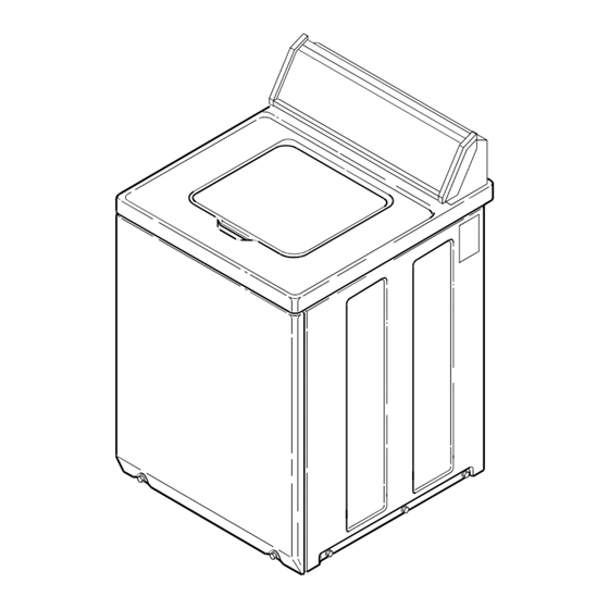
- Page 1 Automatic Washers Refer to Page 6 for Model Numbers W162S Part No. 32305R1 www.comlaundry.com September 2002...
-
Page 2: Table Of Contents
All rights reserved. No part of the contents of this book may be reproduced or transmitted in any form or by any means without the expressed written consent of the publisher. © Copyright, Alliance Laundry Systems LLC – DO NOT COPY or TRANSMIT 32305... - Page 3 Section 9 – Internal Wiring of Washer Motor Switch ..............71 Section 10 – Wiring Diagrams ......73 Models BA4121 and BA4120........74 Model BA3110............75 Models BA2411 and BA2410........76 Model BA2300............77 © Copyright, Alliance Laundry Systems LLC – DO NOT COPY or TRANSMIT 32305...
-
Page 4: Section 1 - Safety Information
• Whenever ground wires are removed during servicing, these ground wires must be reconnected to ensure that the product is properly grounded and to reduce the risk of fire, electric shock, serious injury or death. W006R2 32305 © Copyright, Alliance Laundry Systems LLC – DO NOT COPY or TRANSMIT... -
Page 5: Locating An Authorized Servicer
Locating an Authorized Servicer Alliance Laundry Systems is not responsible for personal injury or property damage resulting from improper service. Review all service information before beginning repairs. Warranty service must be performed by an authorized technician, using authorized factory parts. If service is required after the warranty expires, Alliance Laundry Systems also recommends contacting an authorized technician and using authorized factory parts. -
Page 6: Section 2 - Introduction
When calling or writing about your product, be sure to mention model and serial numbers. Model and serial Nameplate numbers are located on nameplate(s) as shown. W162S © Copyright, Alliance Laundry Systems LLC – DO NOT COPY or TRANSMIT 32305... -
Page 7: Model Identification
Section 2 Introduction Model Identification Information in this manual is applicable to these washer models. BA4121 BA2411 BA4120 BA2410 BA3110 BA2300 © Copyright, Alliance Laundry Systems LLC – DO NOT COPY or TRANSMIT 32305... -
Page 8: Section 3 - Troubleshooting
• Test switch and replace if inoperative. Clogged pressure hose. • Remove and clean or replace hose. Broken, loose or incorrect wiring. • Refer to appropriate wiring diagram. © Copyright, Alliance Laundry Systems LLC – DO NOT COPY or TRANSMIT 32305... -
Page 9: No Warm Water
Timer motor lead wire off timer terminal. • Refer to appropriate wiring diagram and reattach wire. Broken, loose or incorrect wiring. • Refer to appropriate wiring diagram. © Copyright, Alliance Laundry Systems LLC – DO NOT COPY or TRANSMIT 32305... -
Page 10: No Agitation
Inoperative drive motor. • Test motor and replace if inoperative. Shorted or incorrect wiring. • Refer to appropriate wiring diagram. Inoperative transmission assembly. • Repair or replace transmission assembly. © Copyright, Alliance Laundry Systems LLC – DO NOT COPY or TRANSMIT 32305... -
Page 11: Slow Spin Or No Spin
• Repair or replace transmission. Brake pads binding. • Free binding pads, or replace pads. Incorrect voltage. • Contact local utility company, or have a qualified electrician check power supply. © Copyright, Alliance Laundry Systems LLC – DO NOT COPY or TRANSMIT 32305... -
Page 12: Outer Tub Does Not Empty
Pressure hose or accumulator leaking. • Replace pressure hose and/or accumulator. Outer tub cover gasket leaking. • Replace gasket. Tub-to-pump hose leaking at clamp. • Tighten clamp. © Copyright, Alliance Laundry Systems LLC – DO NOT COPY or TRANSMIT 32305... -
Page 13: Section 4 - Grounding
PANEL (Models BA4121, BA4120 and BA3110) MECHANICAL TIMER MODELS Ground Ground Power Ground Wires Wires Cord Ground Wires Power (Some models) Wires (Some models) Cord Figure 2 © Copyright, Alliance Laundry Systems LLC – DO NOT COPY or TRANSMIT 32305... -
Page 14: Power Cord To Control Hood (Models Ba2411, Ba2410 And Ba2300)
16. POWER CORD TO CONTROL HOOD (Models BA2411, BA2410 and BA2300) Ground Wire Figure 3 17. CONTROL HOOD TO BOTTOM FLANGE OF CONTROL PANEL (Models BA2411, BA2410 and BA2300) Ground Wire Figure 4 © Copyright, Alliance Laundry Systems LLC – DO NOT COPY or TRANSMIT 32305... -
Page 15: Main Wire Harness To Top Rear Corner Gusset Of Cabinet
Flange Wire (Some models) on Cabinet Corner Gusset (Some models) Figure 5 19. MOTOR TO MOUNTING BRACKET TO BASE Ground Ground Wire Wire (Some models) Figure 6 © Copyright, Alliance Laundry Systems LLC – DO NOT COPY or TRANSMIT 32305... -
Page 16: Section 5 - Service Procedures
Mallory Timer Eaton Control Timer Knob Assembly Screw End Cap Timer Knob (Right) Skirt Timer Graphic Knob Panel W435P GRAPHICS PANEL, CONTROL HOOD AND CONTROLS Figure 7 © Copyright, Alliance Laundry Systems LLC – DO NOT COPY or TRANSMIT 32305... -
Page 17: Control Panel (Models Ba2411, Ba2410 And Ba2300)
Speed Switch Panel (Action) Assembly Screw Timer (Mallory) Temperature Timer Switch (Singer) Lockwashers Timer Knob Set Screw Control Timer Panel Knob Timer Knob Indicator Lockwashers Figure 8 © Copyright, Alliance Laundry Systems LLC – DO NOT COPY or TRANSMIT 32305... -
Page 18: Timer (Models Ba4121, Ba4120 And Ba3110)
Disengage wire harness terminal block plug(s) from timer by pressing in on movable locking tabs (located on each side of terminal block plug) and pulling away from timer. Refer to Figure 9. © Copyright, Alliance Laundry Systems LLC – DO NOT COPY or TRANSMIT 32305... -
Page 19: Timer (Models Ba2411, Ba2410 And Ba2300)
Before attaching wire harness terminal block to timer, make sure all male terminals on timer are straight and are capable of accepting terminals from wire harness terminal block. © Copyright, Alliance Laundry Systems LLC – DO NOT COPY or TRANSMIT 32305... -
Page 20: Graphic Panel (Models Ba4121, Ba4120 And Ba3110)
Bend tabs on graphic panel (located inside of control hood) straight out toward rear of hood. d. Carefully remove graphic panel off front of control hood. Figure 12 © Copyright, Alliance Laundry Systems LLC – DO NOT COPY or TRANSMIT 32305... -
Page 21: Agitator (Short Post Models)
Then tighten the two wing nuts to hold jaws firmly against drive bell. Refer to Figure 15. © Copyright, Alliance Laundry Systems LLC – DO NOT COPY or TRANSMIT 32305... - Page 22 Install the new seal into the drive bell. Slot n. Remove the seal head from the hub and clean Figure 15 any foreign material from the hub seal mounting area. © Copyright, Alliance Laundry Systems LLC – DO NOT COPY or TRANSMIT 32305...
-
Page 23: To Reinstall Drive Bell
27615, to each of the sealing surfaces where the agitator post gasket will contact the hub. Carefully place new gasket on hub. Be sure holes in gasket are aligned with bolt holes in hub. © Copyright, Alliance Laundry Systems LLC – DO NOT COPY or TRANSMIT 32305... - Page 24 Figure 19. c. While tightening the four cap screws, tap lightly on the drive block to force splines on drive shaft into the coupling on the transmission assembly. © Copyright, Alliance Laundry Systems LLC – DO NOT COPY or TRANSMIT 32305...
-
Page 25: Agitator Drive Shaft (Long Post Models)
Pull bottom of panel away from washer until hold-down clips (located on top flange of panel) disengage from slots in cabinet top. Retainer Thrust Refer to Figure 21. Ring Washer Figure 20 © Copyright, Alliance Laundry Systems LLC – DO NOT COPY or TRANSMIT 32305... -
Page 26: Drive Belt
Screws Pump IDLER PULLEY MUST RIDE ON OUTSIDE Belt OF BELT. Figure 22 d. Run belt off motor pulley, then remove belt from pump pulley. © Copyright, Alliance Laundry Systems LLC – DO NOT COPY or TRANSMIT 32305... - Page 27 Retighten the four attaching screws. Refer to Figure 23. Drive Pulley Wire harness must be installed ahead of spring. Drive Belt Motor Helper Attaching Screws Spring Idler Spring Figure 23 © Copyright, Alliance Laundry Systems LLC – DO NOT COPY or TRANSMIT 32305...
-
Page 28: Motor And Mounting Bracket
Spring Positioning The round spring hook must be hooked in Motor Mounting rear hole for proper Bracket idler lever operation. Motor Ground Attaching Screws Wire Figure 24 © Copyright, Alliance Laundry Systems LLC – DO NOT COPY or TRANSMIT 32305... - Page 29 Ground Wire Idler (Green) Pulley Ground Clip Felt (Clips to the motor Washers mounting bracket) Belt (Agitate and Spin) Nylatron Washer W416P Retainer Belt (Pump) Ring Figure 25 © Copyright, Alliance Laundry Systems LLC – DO NOT COPY or TRANSMIT 32305...
-
Page 30: Motor Drive Pulley
Slide pump and mounting bracket toward rear of washer and lift assembly out of washer. © Copyright, Alliance Laundry Systems LLC – DO NOT COPY or TRANSMIT 32305... -
Page 31: Cabinet Top Assembly
Refer to e. Tape loading door closed. Figure 28. f. Lift front of cabinet top slightly and pull forward to disengage from rear hold-down bracket. © Copyright, Alliance Laundry Systems LLC – DO NOT COPY or TRANSMIT 32305... -
Page 32: Door And Out-Of-Balance Switch And Bracket Assembly
To reduce the risk of personal injury, be careful not to damage door switch and out- of-balance switch assembly when removing the cabinet top. Attaching Screw Figure 29 © Copyright, Alliance Laundry Systems LLC – DO NOT COPY or TRANSMIT 32305... -
Page 33: Mixing Valve Assembly
Refer to Figure 31. Loosen d. Disconnect wires from mixing valve solenoids. hose clamp and move hose to obtain the proper clearance. NOTE: Refer to appropriate wiring diagram when rewiring solenoids. © Copyright, Alliance Laundry Systems LLC – DO NOT COPY or TRANSMIT 32305... - Page 34 Refer to Figure 31. Starting with this hole, place each spring clip in its respective hole and snap in place. Refer to Figure 31 for proper clip installation. © Copyright, Alliance Laundry Systems LLC – DO NOT COPY or TRANSMIT 32305...
-
Page 35: To Remove Lint Filter From Washtub
Refer to Figure 17. b. Hinge cabinet top or remove. Refer to Paragraph 40. c. Disconnect filler hose from backflow preventer. Refer to Figure 30. © Copyright, Alliance Laundry Systems LLC – DO NOT COPY or TRANSMIT 32305... -
Page 36: Water Seal And Hub Assembly
Remove agitator drive bell. Refer to Paragraph panel) disengage from slots in cabinet top. Refer to Figure 21. i. Remove the seal head from the hub. © Copyright, Alliance Laundry Systems LLC – DO NOT COPY or TRANSMIT 32305... -
Page 37: To Install No. 495P3 Hub And Seal Kit
Refer to Figure 38. k. Remove the spline insert from the transmission tube. Apply Outer Tub Bead of Flange No. 27615P Sealant (Step “a”) Flinger Figure 38 © Copyright, Alliance Laundry Systems LLC – DO NOT COPY or TRANSMIT 32305... - Page 38 Carefully place the new washtub gasket will cause a water leak. (supplied in kit) on hub. © Copyright, Alliance Laundry Systems LLC – DO NOT COPY or TRANSMIT 32305...
-
Page 39: To Install Drive Bell And No. 39508P Seal Kit
Install the new seal seat (supplied in kit) into the drive bell. © Copyright, Alliance Laundry Systems LLC – DO NOT COPY or TRANSMIT 32305... -
Page 40: Water Seal Assembly
Leave the garter spring on seal. Place new seal over outer tub flange (with seal lip on outside of tub flange). Then press seal into tub flange opening using moderate finger pressure. © Copyright, Alliance Laundry Systems LLC – DO NOT COPY or TRANSMIT 32305... - Page 41 IMPORTANT: Use caution when tightening cap screws to avoid chipping porcelain on the washtub. f. Lubricate inner splines of new hub assembly (supplied in kit) with No. 27604P Anti-Seize Compound. © Copyright, Alliance Laundry Systems LLC – DO NOT COPY or TRANSMIT 32305...
-
Page 42: Outer Tub
Secure agitator post to hub using cap screws Figure 31. previously removed. o. Carefully place new outer tub cover gasket (supplied in kit) around top rim of outer tub. © Copyright, Alliance Laundry Systems LLC – DO NOT COPY or TRANSMIT 32305... - Page 43 Remove hub from splines on transmission tube. tub. Refer to Figure 43. NOTE: It may be necessary to use a gear puller to remove hub. k. Remove old water seal from outer tub. © Copyright, Alliance Laundry Systems LLC – DO NOT COPY or TRANSMIT 32305...
-
Page 44: Long Post Models
Then lift transmission, balance ring and pivot hinge cabinet top or remove from washer. Refer dome off tub. to Paragraph 40. c. Remove agitator hold-down cap and lift agitator out of washtub. © Copyright, Alliance Laundry Systems LLC – DO NOT COPY or TRANSMIT 32305... - Page 45 Refer to NOTE: It may be necessary to use a gear puller with Figure 31 for proper clip installation. No. 230P4 Guide Tool to remove hub. © Copyright, Alliance Laundry Systems LLC – DO NOT COPY or TRANSMIT 32305...
-
Page 46: Drive Pulley And Helix
(located on top flange of tub. Refer to Figure 43. panel) disengage from slots in cabinet top. Refer to Figure 21. © Copyright, Alliance Laundry Systems LLC – DO NOT COPY or TRANSMIT 32305... - Page 47 If idler lever spring or helper spring complete assembly out of washer. Refer to are overstretched, it will affect the washer Figure 24. operation. Helix Washer Drive WA054-SV Screw Pulley Figure 45 © Copyright, Alliance Laundry Systems LLC – DO NOT COPY or TRANSMIT 32305...
- Page 48 Brake Spacer Rubber Brake Sleeve Assembly Apply Spring Lubricant Here Shoulder Flat Screw Washer Drive Pulley Helix Apply Lubricant Washer Here Screw Support Pivot Dome Figure 46 © Copyright, Alliance Laundry Systems LLC – DO NOT COPY or TRANSMIT 32305...
-
Page 49: Brake Assembly
Springs must be e. Disconnect filler hose from backflow placed in the same notch when reinstalling. Do not overstretch the springs. preventer. Refer to Figure 30. © Copyright, Alliance Laundry Systems LLC – DO NOT COPY or TRANSMIT 32305... - Page 50 Balance Ring Balance Ring Rack Area of Transmission Apply Anti-Seize Compound to this area of both the upper and lower transmission tubes. Transmission Assembly Figure 47 © Copyright, Alliance Laundry Systems LLC – DO NOT COPY or TRANSMIT 32305...
-
Page 51: To Remove Bearing
Remove agitator. Refer to Paragraph 28 for (3) Remove hub from splines on transmission Short Post Drive Models; refer to Paragraph 30 tube. for Long Post Models. © Copyright, Alliance Laundry Systems LLC – DO NOT COPY or TRANSMIT 32305... - Page 52 (if spring are left hooked to motor mounting bracket. present) and large flat washer from transmission. With idler spring and helper spring hooked to © Copyright, Alliance Laundry Systems LLC – DO NOT COPY or TRANSMIT 32305...
-
Page 53: To Disassemble Transmission Assembly
When reinstalling transmission assembly, note washer holding drive pinion to input shaft. there is a mark located on outer edge of balance ring. This mark indicates the heavy side of ring. © Copyright, Alliance Laundry Systems LLC – DO NOT COPY or TRANSMIT 32305... - Page 54 (seals, bearings, etc.). If oil is present between seals and bearings, it will require replacing complete transmission case. Seals and bearings are not available separately. © Copyright, Alliance Laundry Systems LLC – DO NOT COPY or TRANSMIT 32305...
- Page 55 Identification Groove Square Washer Dowel Agitator Pinion Rack Slide 37577P Loctite (Use as a sealant between Transmission Case and Cover.) Dowel Screw Transmission Cover Assembly Figure 48 © Copyright, Alliance Laundry Systems LLC – DO NOT COPY or TRANSMIT 32305...
- Page 56 Shaft Square Washer Dowel Agitator Pinion Lockwasher Slide Rack 37577P Loctite Dowel (Use as a sealant between Transmission Case and Cover.) Screw Transmission Cover Assembly Figure 49 © Copyright, Alliance Laundry Systems LLC – DO NOT COPY or TRANSMIT 32305...
-
Page 57: To Reassemble Transmission Assembly
Place internal gear into transmission case. o. Carefully lower cover onto case. Make sure guide pin on internal gear fits in hole on slide. © Copyright, Alliance Laundry Systems LLC – DO NOT COPY or TRANSMIT 32305... -
Page 58: Balance Ring
Refer to Figure 50. a. Remove transmission assembly. Refer to Paragraph 50, steps “a” through “u”. Ball Screw Bearing Flinger Upper Bearing Housing Outer Upper Bearing Flinger Housing Figure 50 © Copyright, Alliance Laundry Systems LLC – DO NOT COPY or TRANSMIT 32305... -
Page 59: Snubber Pads
NOTE: Springs must be hooked into the center of (with fluffed side up) to the base dome so they the two notches. Refer to Figure 43. are equally spaced. Refer to Figure 51. © Copyright, Alliance Laundry Systems LLC – DO NOT COPY or TRANSMIT 32305... - Page 60 Drive Pulley Idler Drive Lever Belt Helper Spring Back Hole Idler Lever Hook Spring Spring Here Figure 53 © Copyright, Alliance Laundry Systems LLC – DO NOT COPY or TRANSMIT 32305...
-
Page 61: Section 6 - Adjustments
If locknuts are not tight, the washer will not stay level during operation. d. Install rubber cups over leveling legs. © Copyright, Alliance Laundry Systems LLC – DO NOT COPY or TRANSMIT 32305... -
Page 62: Pressure Switch
3/4 of a turn in either direction as the switch may be damaged and flooding could result. Pump Attaching Screws Adjusting Screw Fixed Pressure Switch Adjusting Screw Pump Belt Figure 56 Rotary Pressure Switch Figure 55 © Copyright, Alliance Laundry Systems LLC – DO NOT COPY or TRANSMIT 32305... -
Page 63: Out-Of-Balance Switch Trigger
Refer to Figure 59. Example: If the springs are placed in the upper notch then the trigger must be moved to the extreme right for proper trigger operation. © Copyright, Alliance Laundry Systems LLC – DO NOT COPY or TRANSMIT 32305... -
Page 64: Section 7 - Test Procedures
Continuity (K & G) OPEN Blue to Red OPEN Continuity (K & F) Red to Yellow Continuity (F & L) OPEN Brown to Yellow OPEN Continuity (G & L) © Copyright, Alliance Laundry Systems LLC – DO NOT COPY or TRANSMIT 32305... -
Page 65: Timer No. 28918 Cycle Sequence
360.00 *ON SINGLE SPEED MODEL WASHERS, ALL SPEEDS ARE FAST. KEY: H = HOT W = WARM C = COLD TIMER NO. 28918 CYCLE SEQUENCE (TWO CYCLE) © Copyright, Alliance Laundry Systems LLC – DO NOT COPY or TRANSMIT 32305... -
Page 66: Timer No. 31239 Cycle Sequence
360.00 *ON SINGLE SPEED MODEL WASHERS, ALL SPEEDS ARE FAST. KEY: H = HOT W = WARM C = COLD TIMER NO. 31239 CYCLE SEQUENCE (THREE CYCLE) © Copyright, Alliance Laundry Systems LLC – DO NOT COPY or TRANSMIT 32305... -
Page 67: Section 9 - Internal Wiring Of Washer Motor Switch
Yellow Blue Brown Blue Black Orange Violet Yellow Pink Blue Brown Yellow White Brown Yellow White Pink Blue Emerson General Electric 27179P MOTOR ASSEMBLY (2 SPEED MOTORS) © Copyright, Alliance Laundry Systems LLC – DO NOT COPY or TRANSMIT 32305... -
Page 68: Section 10 - Wiring Diagrams
W030 WIRING DIAGRAMS AND SCHEMATICS FOUND ON THE FOLLOWING PAGES ARE FOR MODELS COVERED IN THIS MANUAL. © Copyright, Alliance Laundry Systems LLC – DO NOT COPY or TRANSMIT 32305... -
Page 69: Models Ba4121 And Ba4120
Failure to install, maintain, and/or operate this machine according to the manufacturer's instructions may result in conditions which can produce bodily injury and/or property damage. W030 MODELS BA4121 AND BA4120 © Copyright, Alliance Laundry Systems LLC – DO NOT COPY or TRANSMIT 32305... -
Page 70: Model Ba3110
Failure to install, maintain, and/or operate this machine according to the manufacturer's instructions may result in conditions which can produce bodily injury and/or property damage. W030 MODEL BA3110 © Copyright, Alliance Laundry Systems LLC – DO NOT COPY or TRANSMIT 32305... -
Page 71: Models Ba2411 And Ba2410
Failure to install, maintain, and/or operate this machine according to the manufacturer's instructions may result in conditions which can produce bodily injury and/or property damage. W030 MODELS BA2411 AND BA2410 © Copyright, Alliance Laundry Systems LLC – DO NOT COPY or TRANSMIT 32305... -
Page 72: Model Ba2300
Failure to install, maintain, and/or operate this machine according to the manufacturer's instructions may result in conditions which can produce bodily injury and/or property damage. W030 MODEL BA2300 © Copyright, Alliance Laundry Systems LLC – DO NOT COPY or TRANSMIT 32305...
Need help?
Do you have a question about the BA4121 and is the answer not in the manual?
Questions and answers