
Subscribe to Our Youtube Channel
Related Manuals for Lectrosonics SR175


Summary of Contents for Lectrosonics SR175
- Page 1 SR175 COMPACT RECEIVER OPERATING INSTRUCTIONS and trouble-shooting guide Digital Code Squelch LECTROSONICS, INC. Rio Rancho, NM...
-
Page 2: Table Of Contents
RETURNING UNITS FOR REPAIR ...... 7 SR175 SPECIFICATIONS AND FEATURES ..... . . 8 WARRANTY . -
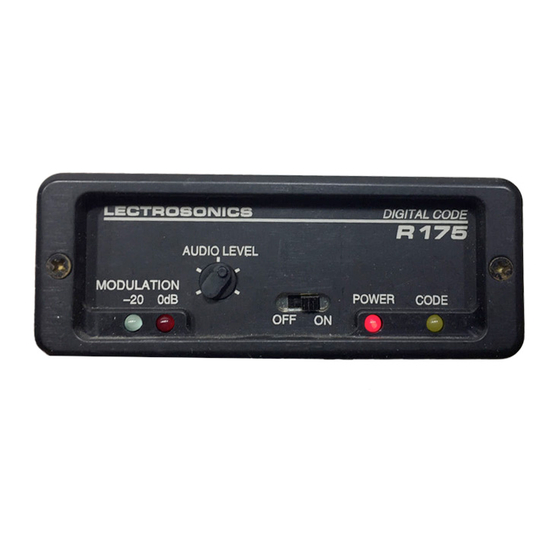
Page 3: Receiver Front Panel
Intermediate settings are often necessary to ideally match the level with other equipment. LECTROSONICS SR175 DIGITAL CODE OUTPUT LEVEL LIMIT POWER CODE Figure 1 -SR175 Front Panel... -
Page 4: Receiver Rear Panel
Being such a common type of connector, many different adapters and cords are available from local audio or electronics dealers in your area, or from the factory. The pin configuration is: Pin 1 - shield Pin 2 - Audio (+) Pin 3 - Audio (-) 12V DC AUDIO OUT Figure 2 - SR175 Rear Panel... -
Page 5: System Setup And Operation
SYSTEM SETUP AND OPERATION Connect the supplied CH-12 to the power jack on the rear panel. Attach the antenna. Connect the audio cable. XLR Output: Pin 1 - ground Pin 2 - audio (+) Pin 3 - audio (-) Set front panel switch to "ON." Check to see that the red POWER LED lights up. -
Page 6: Antenna Use And Placement
Lectrosonics transmitters radiate more power, and the receivers are more sensitive than any other on the market. This reduces dropouts to an insignificant level. If, however, you do encounter dropouts frequently, call the factory. -
Page 7: Troubleshooting
TROUBLESHOOTING Before going through the following chart, be sure that you have a good battery in the transmitter. It is important that you follow these steps in the sequence listed. SYMPTOM POSSIBLE CAUSE TRANSMITTER BATTERY LED OFF 1) Battery is inserted backwards. 2) Battery is dead. -
Page 8: Service And Repair
There are no adjustments inside that will make a malfunctioning unit start working. LECTROSONICS service department is equipped and staffed to quickly repair your equipment. In-warranty repairs are made at no charge in accordance with the terms of the warranty. Out of warranty repairs are charged at a modest flat rate plus parts and shipping. -
Page 9: Sr175 Specifications And Features
SR175 SPECIFICATIONS AND FEATURES Operating Frequencies: 169 to 186 MHz, crystal controlled RF Sensitivity: -110 dBm for 20 dB Sinad (0.7 uV) IF Selectivity: 150 kHz interference bandwidth -30 dB @ ±200 kHz Squelch Quieting: -109 dB AM Rejection: Below the noise at all input levels ±15 kHz... -
Page 10: Limited One Year Warranty
This warranty gives you specific legal rights. You may have additional legal rights which vary from state to state. LECTROSONICS, INC. 581 LASER ROAD RIO RANCHO, NM 87124 USA November 10, 1994...
Need help?
Do you have a question about the SR175 and is the answer not in the manual?
Questions and answers