
Related Manuals for Nokia c2-00


Summary of Contents for Nokia c2-00
- Page 1 Nokia Customer Care Service Manual RM-704 (Nokia C2-00) Mobile Terminal Part No: (Issue 1) COMPANY CONFIDENTIAL Copyright © 2011 Nokia. All rights reserved.
- Page 2 RM-704 Amendment Record Sheet Amendment Record Sheet Amendment No Date Inserted By Comments Original issue 05/2011 Jeff Zhao Page ii COMPANY CONFIDENTIAL Issue 1 Copyright © 2011 Nokia. All rights reserved.
- Page 3 Nokia operates a policy of continuous development. Nokia reserves the right to make changes and improvements to any of the products described in this document without prior notice. Under no circumstances shall Nokia be responsible for any loss of data or income or any special, incidental, consequential or indirect damages howsoever caused.
-
Page 4: Warnings And Cautions
WCDMA networks and cause problems to 3G cellular phone communication in a wide area. • During testing never activate the GSM or WCDMA transmitter without a proper antenna load, otherwise GSM or WCDMA PA may be damaged. Page iv COMPANY CONFIDENTIAL Issue 1 Copyright © 2011 Nokia. All rights reserved. - Page 5 Use only approved accessories and batteries. Do not connect incompatible products. CONNECTING TO OTHER DEVICES When connecting to any other device, read its user’s guide for detailed safety instructions. Do not connect incompatible products. Issue 1 COMPANY CONFIDENTIAL Page v Copyright © 2011 Nokia. All rights reserved.
- Page 6 All of the above suggestions apply equally to the product, battery, charger or any accessory. Page vi COMPANY CONFIDENTIAL Issue 1 Copyright © 2011 Nokia. All rights reserved.
- Page 7 RM-704 ESD protection ESD protection Nokia requires that service points have sufficient ESD protection (against static electricity) when servicing the phone. Any product of which the covers are removed must be handled with ESD protection. The SIM card can be replaced without ESD protection if the product is otherwise ready for use.
-
Page 8: Battery Information
Batteries' performance is particularly limited in temperatures well below freezing. Do not dispose of batteries in a fire! Dispose of batteries according to local regulations (e.g. recycling). Do not dispose as household waste. Page viii COMPANY CONFIDENTIAL Issue 1 Copyright © 2011 Nokia. All rights reserved. - Page 9 Our policy is of continuous development; details of all technical modifications will be included with service bulletins. While every endeavour has been made to ensure the accuracy of this document, some errors may exist. If any errors are found by the reader, NOKIA MOBILE PHONES Business Group should be notified in writing/e- mail. Please state: •...
- Page 10 RM-704 Company policy (This page left intentionally blank.) Page x COMPANY CONFIDENTIAL Issue 1 Copyright © 2011 Nokia. All rights reserved.
- Page 11 Nokia C2-00 Service Manual Structure 1 General Information 2 Service Tools and Service Concepts 3 BB Troubleshooting and Manual Tuning Guide 4 RF Troubleshooting 5 System Module Glossary Issue 1 COMPANY CONFIDENTIAL Page xi Copyright © 2011 Nokia. All rights reserved.
- Page 12 RM-704 Nokia C2-00 Service Manual Structure (This page left intentionally blank.) Page xii COMPANY CONFIDENTIAL Issue 1 Copyright © 2011 Nokia. All rights reserved.
- Page 13 Nokia Customer Care 1 — General Information Issue 1 COMPANY CONFIDENTIAL Page 1 – 1 Copyright © 2011 Nokia. All rights reserved.
- Page 14 RM-704 General Information (This page left intentionally blank.) Page 1 – 2 COMPANY CONFIDENTIAL Issue 1 Copyright © 2011 Nokia. All rights reserved.
-
Page 15: Table Of Contents
1–6 Technical specifications ............................1–7 Transceiver general specifications ......................... 1–7 Battery endurance............................1–7 List of Figures Figure 1 RM-704 (Nokia C2-00) product picture ....................1–5 Issue 1 COMPANY CONFIDENTIAL Page 1 – 3 Copyright © 2011 Nokia. All rights reserved. - Page 16 RM-704 General Information (This page left intentionally blank.) Page 1 – 4 COMPANY CONFIDENTIAL Issue 1 Copyright © 2011 Nokia. All rights reserved.
-
Page 17: Product Selection
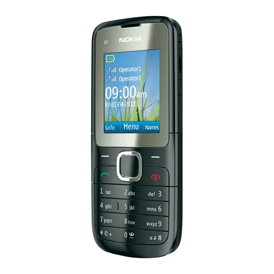
RM-704 General Information Product selection RM-704 (Nokia C2–00) is a GSM Quad-band phone, supporting EGSM 900/1800 bands. Figure 1 RM-704 (Nokia C2-00) product picture Phone features Hardware features • One internal SIM slot under battery • One external SIM slot, hot-swap enabled •... -
Page 18: Accessories
• Phone: Nokia C2–00 • Battery: BL-5C • Chargers: AC-3 (China use AC-8C and CA-100C) • Headset: WH-102 For out-box accessories, please refer to enhancement list document. Page 1 – 6 COMPANY CONFIDENTIAL Issue 1 Copyright © 2011 Nokia. All rights reserved. -
Page 19: Technical Specifications
Variation in operation time will occur depending on SIM card, network settings and usage. Talk time is increased by up to 30% if half rate is active and reduced by 5% if enhanced full rate is active. Issue 1 COMPANY CONFIDENTIAL Page 1 – 7 Copyright © 2011 Nokia. All rights reserved. - Page 20 RM-704 General Information (This page left intentionally blank.) Page 1 – 8 COMPANY CONFIDENTIAL Issue 1 Copyright © 2011 Nokia. All rights reserved.
- Page 21 Nokia Customer Care 2 — Service Tools and Service Concepts Issue 1 COMPANY CONFIDENTIAL Page 2 – 1 Copyright © 2011 Nokia. All rights reserved.
- Page 22 RM-704 Service Tools and Service Concepts (This page left intentionally blank.) Page 2 – 2 COMPANY CONFIDENTIAL Issue 1 Copyright © 2011 Nokia. All rights reserved.
-
Page 23: Table Of Contents
Figure 3 Flashing, certificate restore and product code change ..............2–13 Figure 4 Flashing, certificate restore, product code change and EM calibration......... 2–14 Figure 5 BB and RF tuning ..........................2–15 Issue 1 COMPANY CONFIDENTIAL Page 2 – 3 Copyright © 2011 Nokia. All rights reserved. - Page 24 RM-704 Service Tools and Service Concepts (This page left intentionally blank.) Page 2 – 4 COMPANY CONFIDENTIAL Issue 1 Copyright © 2011 Nokia. All rights reserved.
-
Page 25: Service Tools
The table below gives a short overview of service devices that can be used for testing, error analysis, and repair of product RM-704. For the correct use of the service devices, and the best effort of workbench setup, please refer to various concepts. Issue 1 COMPANY CONFIDENTIAL Page 2 – 5 Copyright © 2011 Nokia. All rights reserved. - Page 26 5 Start service software. Note: Service software enables CU-4 regulators via USB when it is started. Reconnecting the power supply requires a service software restart. Page 2 – 6 COMPANY CONFIDENTIAL Issue 1 Copyright © 2011 Nokia. All rights reserved.
-
Page 27: Fps-21
In order to access the SD memory card slots inside FPS-21, the prommer needs to be opened by removing the front panel, rear panel and heatsink from the prommer body. Issue 1 COMPANY CONFIDENTIAL Page 2 – 7 Copyright © 2011 Nokia. All rights reserved. - Page 28 RJ-230 is a soldering jig used for soldering and as a rework jig for the engine module. SRT-6 Opening tool SRT-6 is used to open phone covers. Note: The SRT-6 is included in the Nokia Standard Toolkit. Page 2 – 8 COMPANY CONFIDENTIAL Issue 1 Copyright © 2011 Nokia. All rights reserved.
-
Page 29: Cables
SS-93 Opening tool SS-93 is used for opening JAE connectors. Note: The SS-93 is included in Nokia Standard Toolkit. SX-4 Smart card SX-4 is a BB5 security device used to protect critical features in tuning and testing. SX-4 is also needed together with FPS-21 when DCT-4 phones are flashed. -
Page 30: Ca-128Rs
FPS-21 sales package. CA-89DS Cable Provides VBAT and Flashbus connections to mobile device programming adapters. CA-99PS Adapter CA-99PS adapter, 3.5 jack to 5.5 plug. Page 2 – 10 COMPANY CONFIDENTIAL Issue 1 Copyright © 2011 Nokia. All rights reserved. - Page 31 The RF cable is used to connect, for example, a module repair jig to the RF measurement equipment. SMA to N-Connector approximately 610 mm. Attenuation for: • GSM850/900: 0.3+-0.1 dB • GSM1800/1900: 0.5+-0.1 dB • WCDMA/WLAN: 0.6+-0.1dB Issue 1 COMPANY CONFIDENTIAL Page 2 – 11 Copyright © 2011 Nokia. All rights reserved.
-
Page 32: Service Concepts
POS (Point of Sale) flash concept Figure 2 POS flash concept Type Description Product specific tools BL-5C Battery Other tools PC with Care Suite Cables CA-101 Micro USB cable Page 2 – 12 COMPANY CONFIDENTIAL Issue 1 Copyright © 2011 Nokia. All rights reserved. -
Page 33: Flashing, Certificate Restore And Product Code Change
Flash prommer box AC-35 Power supply PK-1 SW security device SX-4 Smart card PC with service software (Phoenix) Cables CA-101 Micro USB cable USB cable Issue 1 COMPANY CONFIDENTIAL Page 2 – 13 Copyright © 2011 Nokia. All rights reserved. -
Page 34: Flashing, Certificate Restore, Product Code Change And Em Calibration
SW security device SX-4 Smart card PC with service software (Phoenix) Cables CA-101 Micro USB cable CA-89DS Service cable CA-99PS Adapter PCS-1 Power cable USB cable Page 2 – 14 COMPANY CONFIDENTIAL Issue 1 Copyright © 2011 Nokia. All rights reserved. -
Page 35: Bb And Rf Tuning
Measurement equipment Cables CA-101 Micro USB cable PCS-1 DC power cable XRS-6 RF cable USB cable GPIB control cable CA-128RS Product specific RF adapter cable Issue 1 COMPANY CONFIDENTIAL Page 2 – 15 Copyright © 2011 Nokia. All rights reserved. - Page 36 RM-704 Service Tools and Service Concepts (This page left intentionally blank.) Page 2 – 16 COMPANY CONFIDENTIAL Issue 1 Copyright © 2011 Nokia. All rights reserved.
- Page 37 Nokia Customer Care 3 — BB Troubleshooting and Manual Tuning Guide Issue 1 COMPANY CONFIDENTIAL Page 3 – 1 Copyright © 2011 Nokia. All rights reserved.
- Page 38 RM-704 BB Troubleshooting and Manual Tuning Guide (This page left intentionally blank.) Page 3 – 2 COMPANY CONFIDENTIAL Issue 1 Copyright © 2011 Nokia. All rights reserved.
-
Page 39: List Of Figures
Figure 14 32 KHz RTC clock does not work ...................... 3–11 Figure 15 Cannot identify charger ........................3–14 Figure 16 No charging current .......................... 3–15 Figure 17 Cannot identify SIM card........................3–15 Issue 1 COMPANY CONFIDENTIAL Page 3 – 3 Copyright © 2011 Nokia. All rights reserved. - Page 40 ....................3–31 Figure 35 Test arrangement for external microphone................... 3–32 Figure 36 external microphone troubleshooting flow................... 3–32 Figure 37 Test arrangement for headset speaker................... 3–33 Page 3 – 4 COMPANY CONFIDENTIAL Issue 1 Copyright © 2011 Nokia. All rights reserved.
-
Page 41: Baseband Troubleshooting
The following sections will contain in-depth trouble-shooting guides for various areas of the baseband circuit. It is assumed that a battery simulator containing a valid BSI resistance is used to supply the phone, or a valid battery is used. Issue 1 COMPANY CONFIDENTIAL Page 3 – 5 Copyright © 2011 Nokia. All rights reserved. -
Page 42: Phone Does Not Power On
High current If the phone draws excessively high current upon power on or insertion of battery, it means that VBAT or a LDO output is shorted. Page 3 – 6 COMPANY CONFIDENTIAL Issue 1 Copyright © 2011 Nokia. All rights reserved. -
Page 43: Listing 1: High Current When Battery Is Inserted, I>500Ma;
Listing 1: High current when battery is inserted, I>500mA; Figure 8 High current when battery inserted Refer to the following picture: Figure 9 IR picture showing component overheat Issue 1 COMPANY CONFIDENTIAL Page 3 – 7 Copyright © 2011 Nokia. All rights reserved. -
Page 44: Listing 2: High Current After Pressing Power-On Key, 100Ma
RM-704 BB Troubleshooting and Manual Tuning Guide Listing 2: High current after pressing power-on key, 100mA<I<500mA. Figure 11 High current after pressing power-on key Page 3 – 8 COMPANY CONFIDENTIAL Issue 1 Copyright © 2011 Nokia. All rights reserved. -
Page 45: Clocking System Troubleshooting
26 MHz clock does not work If the 26 MHz crystal does not work, it may be due to B7100 malfunction or a soldering defect. Issue 1 COMPANY CONFIDENTIAL Page 3 – 9 Copyright © 2011 Nokia. All rights reserved. - Page 46 32 KHz RTC clock does not work If the 32 KHz crystal does not work, it may be due to B3000 malfunction, matching capacitor or B3000 soldering defect. Page 3 – 10 COMPANY CONFIDENTIAL Issue 1 Copyright © 2011 Nokia. All rights reserved.
-
Page 47: Flash Programming Troubleshootin
USB connection is verified prior to flashing troubleshooting. The Phoenix tool can give some useful information about the failure as indicated in the following programming troubleshooting flow. Issue 1 COMPANY CONFIDENTIAL Page 3 – 11 Copyright © 2011 Nokia. All rights reserved. -
Page 48: Main Memory Troubleshooting
BB Troubleshooting and Manual Tuning Guide Troubleshooting flow Main memory troubleshooting Context Possible issues happen on the main memory could be: image corruption, soldering issue or flash chip damaged. Page 3 – 12 COMPANY CONFIDENTIAL Issue 1 Copyright © 2011 Nokia. All rights reserved. -
Page 49: Charging Troubleshooting
When inserting the wall adaptor into the phone, the phone will detect a valid voltage if charger output voltage is 4.6 – 9.3V. But if something is wrong with the voltage detect/measurement circuit, then the phone cannot correctly identify the charger. Issue 1 COMPANY CONFIDENTIAL Page 3 – 13 Copyright © 2011 Nokia. All rights reserved. - Page 50 It is assumed that phone can detect the presence of the charger, otherwise please refer to the above section. Page 3 – 14 COMPANY CONFIDENTIAL Issue 1 Copyright © 2011 Nokia. All rights reserved.
-
Page 51: Sim Card Troubleshooting
SIM card. When the phone is switched on, the phone first checks for a 1.8V SIM card, and then for a 3V SIM card. The phone will try this several times, where after it will display “Insert SIM card”. Figure 17 Cannot identify SIM card Issue 1 COMPANY CONFIDENTIAL Page 3 – 15 Copyright © 2011 Nokia. All rights reserved. - Page 52 The first data is always ATR and it is sent from card to phone. For reference a picture with normal SIM power-up is shown below. Figure 19 SIM voltages, normal startup at 3V Page 3 – 16 COMPANY CONFIDENTIAL Issue 1 Copyright © 2011 Nokia. All rights reserved.
-
Page 53: Dual Sim Troubleshooting
SIM1 is done using only one SIM card, which is inserted either in slot 1, and troubleshooting on SIM2 is done using 2 SIM cards, so both slots needs to be occupied. SIM 1 not recognized Figure 20 SIM 1 troubleshooting flow Issue 1 COMPANY CONFIDENTIAL Page 3 – 17 Copyright © 2011 Nokia. All rights reserved. -
Page 54: Usb Troubleshooting
If the phone cannot be detected by PC when the USB cable is inserted, this means that communication between phone and PC can not be setup. This may be due to soldering issue or a malfunction in the ESD protection device. Page 3 – 18 COMPANY CONFIDENTIAL Issue 1 Copyright © 2011 Nokia. All rights reserved. - Page 55 RM-704 BB Troubleshooting and Manual Tuning Guide Troubleshooting flow Issue 1 COMPANY CONFIDENTIAL Page 3 – 19 Copyright © 2011 Nokia. All rights reserved.
-
Page 56: User Interface Troubleshooting
BB Troubleshooting and Manual Tuning Guide Figure 22 Pin 3 of V2202 User interface troubleshooting Keyboard troubleshooting Context One or more keys don’t function at all. Page 3 – 20 COMPANY CONFIDENTIAL Issue 1 Copyright © 2011 Nokia. All rights reserved. -
Page 57: Display Troubleshooting
LCD correctly. The XGOLD also feeds 2 power supplies to the LCD: VAUX and 1V8, if these 2 power supply work abnormally, the LCD also doesn’t work. Issue 1 COMPANY CONFIDENTIAL Page 3 – 21 Copyright © 2011 Nokia. All rights reserved. -
Page 58: Backlight Troubleshooting
The backlight is driven by a DC-DC converter. The LCD backlight LED’s and the keypad LED’s are in connected in serial path. If any component on this serial path is open circuit, there is no backlight. Page 3 – 22 COMPANY CONFIDENTIAL Issue 1 Copyright © 2011 Nokia. All rights reserved. -
Page 59: Camera Interface Troubleshooting
In the following troubleshooting guide it is assumed that the integrity of this interface is already verified and valid signal are present on the inputs of N3000. Issue 1 COMPANY CONFIDENTIAL Page 3 – 23 Copyright © 2011 Nokia. All rights reserved. - Page 60 Actual pixel clock frequency, Vsync and Hsync frequency and data content will depend on the camera used (resolution, frame-rate) and operating mode (still picture capture, video recording, viewfinder mode). Page 3 – 24 COMPANY CONFIDENTIAL Issue 1 Copyright © 2011 Nokia. All rights reserved.
-
Page 61: No Valid Data From Camera Interface Ic
CCP_CLASS_SEL = GND: SMIA Class 0, Strobe pins functions as Clock inputs (ACME VGA module) CCP_CLASS_SEL = 1.8V: SMIA Class 1, Strobe and Data. (2MP Gandalf module) Issue 1 COMPANY CONFIDENTIAL Page 3 – 25 Copyright © 2011 Nokia. All rights reserved. -
Page 62: Audio Troubleshooting
RM-704 BB Troubleshooting and Manual Tuning Guide Audio troubleshooting Audio troubleshooting test instructions Audio troubleshooting using phoenix: Figure 27 Phoenix audio test window Page 3 – 26 COMPANY CONFIDENTIAL Issue 1 Copyright © 2011 Nokia. All rights reserved. -
Page 63: Internal Microphone Troubleshooting
2 Open “audio test” window from “Testing –> Audio test”, as shown in Figure Phoenix audio test window above. 3 Select “Hp microphone in Ext speaker out”. Issue 1 COMPANY CONFIDENTIAL Page 3 – 27 Copyright © 2011 Nokia. All rights reserved. - Page 64 6 Check if signal is detected at HS_EAR_L/R pads, as shown in Figure “PWB audio test points” above. Figure 29 Test arrangement for microphone Figure 30 Internal microphone troubleshooting flow Page 3 – 28 COMPANY CONFIDENTIAL Issue 1 Copyright © 2011 Nokia. All rights reserved.
-
Page 65: Internal Earpiece Troubleshooting
5 Input signal to HS_MIC/GND pads, as shown in Figure PWB audio test point above, for example 100mVpp, 1kHz. 6 Check if sound is heard in earpiece. Figure 31 Test arrangement for earpiece Issue 1 COMPANY CONFIDENTIAL Page 3 – 29 Copyright © 2011 Nokia. All rights reserved. -
Page 66: Ihf Speaker Troubleshooting
5 Input signal to HS_MIC/GND pads, as shown in Figure PWB audio test point above, for example 100mVpp, 1kHz. 6 6) Check if sound is heard in IHF. Page 3 – 30 COMPANY CONFIDENTIAL Issue 1 Copyright © 2011 Nokia. All rights reserved. -
Page 67: External Microphone Troubleshooting
5 Input sound at microphone port, for example 94dB SPL 1kHz. 6 Check if signal is detected at HS_EAR_L/R pads, shown in Figure PWB audio test points above. Issue 1 COMPANY CONFIDENTIAL Page 3 – 31 Copyright © 2011 Nokia. All rights reserved. -
Page 68: Headset Speaker Troubleshooting
5 Input signal to HS_MIC/GND pads, as shown in Figure PWB audio test point above, for example 100mVpp, 1kHz. 6 Check if sound is heard in headset. Page 3 – 32 COMPANY CONFIDENTIAL Issue 1 Copyright © 2011 Nokia. All rights reserved. -
Page 69: Fm Radio Troubleshooting
FM stations with sufficient signal strength are available on the point of service, and that a dedicated FM signal generator is not used during troubleshooting. Issue 1 COMPANY CONFIDENTIAL Page 3 – 33 Copyright © 2011 Nokia. All rights reserved. - Page 70 RM-704 BB Troubleshooting and Manual Tuning Guide Troubleshooting flow Page 3 – 34 COMPANY CONFIDENTIAL Issue 1 Copyright © 2011 Nokia. All rights reserved.
-
Page 71: Memory Card Troubleshooting
Quantum support SD/MMC card. Troubleshooting flow Baseband manual tuning guide Certificate restoring BB5 Context This procedure is performed when the Combo Memory is replaced. Hardware and Software Setup: Issue 1 COMPANY CONFIDENTIAL Page 3 – 35 Copyright © 2011 Nokia. All rights reserved. - Page 72 3. Select OK, Phoenix will read product information from phone. 4. Product code shown on the UI does not matter, because during restoring it will be replaced by the product code which is the latest one stored in Nokia system. Page 3 – 36...
- Page 73 SW downgrade which causes the phone to die. 6. Information from phone and Smart Card are read and connection to Tucson server is established. 7. Information from Nokia system is retrieved and programmed in the phone. Issue 1 COMPANY CONFIDENTIAL Page 3 –...
- Page 74 RM-704 BB Troubleshooting and Manual Tuning Guide 8. After programming confirmation about successful event is sent to Nokia system. Page 3 – 38 COMPANY CONFIDENTIAL Issue 1 Copyright © 2011 Nokia. All rights reserved.
-
Page 75: Energy Management Calibration
3. Choose File -> Scan Product. 4. Choose Tuning -> Energy Management. 5. To show the current values in the phone memory, click Read. 6. Click Tune & Calculate. Issue 1 COMPANY CONFIDENTIAL Page 3 – 39 Copyright © 2011 Nokia. All rights reserved. - Page 76 8. Click Read, and confirm that the new calibration values are stored in the phone memory correctly. 9. End the procedure and close the Energy Management window. Page 3 – 40 COMPANY CONFIDENTIAL Issue 1 Copyright © 2011 Nokia. All rights reserved.
- Page 77 Nokia Customer Care 4 — RF Troubleshooting Issue 1 COMPANY CONFIDENTIAL Page 4 – 1 Copyright © 2011 Nokia. All rights reserved.
- Page 78 RM-704 RF Troubleshooting (This page left intentionally blank.) Page 4 – 2 COMPANY CONFIDENTIAL Issue 1 Copyright © 2011 Nokia. All rights reserved.
-
Page 79: Issue
Configuration of testing and tuning tools....................4–40 Configure connections between phone and PC ..................4–40 Preferences ............................... 4–41 RF tuning ................................ 4–45 ................................... 4–45 RF testing ............................... 4–48 Issue 1 COMPANY CONFIDENTIAL Page 4 – 3 Copyright © 2011 Nokia. All rights reserved. - Page 80 Figure 48 TX HB VPC logic waveform-PCL0 (C1: VPC; C2: PAEN)..............4–25 Figure 49 Bluetooth block diagram........................4–51 Figure 50 Test points in Archie Bluetooth ASIC circuit – BTHCost4.0D (CSR8810)........4–53 Page 4 – 4 COMPANY CONFIDENTIAL Issue 1 Copyright © 2011 Nokia. All rights reserved.
-
Page 81: Introduction To Rf Troubleshooting
After this a re-tuning + verification of the phone is needed in order to secure passes of all RF parameters and no more failures will be present. Issue 1 COMPANY CONFIDENTIAL Page 4 – 5 Copyright © 2011 Nokia. All rights reserved. -
Page 82: Maintenance Step 1
Detect if other failures are present after replacing. • To make a final calibration and verification (local mode) to make sure that the phone passes all RF limits and requirements. Page 4 – 6 COMPANY CONFIDENTIAL Issue 1 Copyright © 2011 Nokia. All rights reserved. -
Page 83: Maintenance Step 4
Below is the working flow illustrated for the case where all Self-test fails the X-Tal, Antenna detection or FEM ID Self-test in the Maintenance step. Issue 1 COMPANY CONFIDENTIAL Page 4 – 7 Copyright © 2011 Nokia. All rights reserved. -
Page 84: Case 3: Rf Internal Loopback Failure
MS is assembled in Maintenance step 4 and verified in normal mode. Maintenance step 1—Self test Maintenance step 1 — Self test Run all self-tests in order to clarify if the Self-Test can detect any failures. Page 4 – 8 COMPANY CONFIDENTIAL Issue 1 Copyright © 2011 Nokia. All rights reserved. -
Page 85: Maintenance Step 2 -Debugging And Troubleshooting
The purpose of the visual inspection is to try by visual to identify the area or component of root cause i.e. locate burned components (mal colure), destroyed components, misplaced components and other visual abnormalities. Issue 1 COMPANY CONFIDENTIAL Page 4 – 9 Copyright © 2011 Nokia. All rights reserved. - Page 86 RM-704 RF Troubleshooting Page 4 – 10 COMPANY CONFIDENTIAL Issue 1 Copyright © 2011 Nokia. All rights reserved.
-
Page 87: Rf Troubleshooting: X-Tal Debug Check Flow
RM-704 RF Troubleshooting RF Troubleshooting: X-Tal debug check flow Issue 1 COMPANY CONFIDENTIAL Page 4 – 11 Copyright © 2011 Nokia. All rights reserved. -
Page 88: Rf Troubleshooting: Antenna Detection Check Flow
RM-704 RF Troubleshooting RF Troubleshooting: Antenna detection check flow Page 4 – 12 COMPANY CONFIDENTIAL Issue 1 Copyright © 2011 Nokia. All rights reserved. -
Page 89: Rf Troubleshooting: Afc Troubleshooting
RXLB_MN C7115, L7100, C7126 RXHB_MN C7114, L7101, C7129 FEM_RxCtl VC1, VC2, VC3, FEM_RxCtrlRes R7106, R7110, R7113 FEM_RxCtrlCap C7107, C7110, C7132 FEM_BatComp L7707, C7135, C7125, C7117, C7111 Issue 1 COMPANY CONFIDENTIAL Page 4 – 13 Copyright © 2011 Nokia. All rights reserved. -
Page 90: Rx Lb Troubleshooting
GSM burst signal in local mode. To excite the RSSI detector in the same way a modulated GSM signal does, the test signal must either be GMSK modulated (Pseudo-random bit sequence (PRBS)) or an un-modulated CW-signal with 67.7kHz offset from center frequency. Page 4 – 14 COMPANY CONFIDENTIAL Issue 1 Copyright © 2011 Nokia. All rights reserved. - Page 91 RM-704 RF Troubleshooting Issue 1 COMPANY CONFIDENTIAL Page 4 – 15 Copyright © 2011 Nokia. All rights reserved.
- Page 92 Ball No. Test point Function VBAT C7134 3.6V typ. Battery voltage, supply voltage of D2B LDO VDDRF2 C7106 2.5V D2B output voltage, part of RF supply Page 4 – 16 COMPANY CONFIDENTIAL Issue 1 Copyright © 2011 Nokia. All rights reserved.
- Page 93 1.3V VDD for Time to Digital Converter of DPLL VDDMS C7123 1.3V Mixed signal supply VDDXO C7130 1.3V DCXO supply VDDMMD NONE 1.3V VDD for Multi Modulus Divider of DPLL Issue 1 COMPANY CONFIDENTIAL Page 4 – 17 Copyright © 2011 Nokia. All rights reserved.
-
Page 94: Rx Hb Troubleshooting
RM-704 RF Troubleshooting RX HB troubleshooting Page 4 – 18 COMPANY CONFIDENTIAL Issue 1 Copyright © 2011 Nokia. All rights reserved. -
Page 95: Transmitter Troubleshooting
TXLB_H4FILTER C7108, C7120, L7504 TXHB_H2FILTER C7109, C7101, L7106 FEM_TxCtl VC1,VC2, VC3, PAEN FEM_TxCtrlRes R7106, R7110, R7113,R7100 FEM_TxCtrlCap C7105, C7107, C7110,C7132 FEM_BatComp L7707, C7135, C7125, C7117, C7111 Issue 1 COMPANY CONFIDENTIAL Page 4 – 19 Copyright © 2011 Nokia. All rights reserved. - Page 96 RM-704 RF Troubleshooting Figure 43 TX checkpoints and component overview (measurement point marked with blue) Page 4 – 20 COMPANY CONFIDENTIAL Issue 1 Copyright © 2011 Nokia. All rights reserved.
-
Page 97: Tx Lb Troubleshooting
RM-704 RF Troubleshooting TX LB troubleshooting Issue 1 COMPANY CONFIDENTIAL Page 4 – 21 Copyright © 2011 Nokia. All rights reserved. - Page 98 RM-704 RF Troubleshooting Figure 44 X-Gold TX pin volts @ C7108(LB) /C7109 (HB) Figure 45 RX LB FEM logic waveform (C1:VC1; C2:VC2; C3:VC3) Page 4 – 22 COMPANY CONFIDENTIAL Issue 1 Copyright © 2011 Nokia. All rights reserved.
- Page 99 RM-704 RF Troubleshooting Figure 46 TX LB VPC logic waveform-PCL5 (C1: VPC; C2: PAEN) Issue 1 COMPANY CONFIDENTIAL Page 4 – 23 Copyright © 2011 Nokia. All rights reserved.
-
Page 100: Tx Hb Troubleshooting
RM-704 RF Troubleshooting TX HB troubleshooting Page 4 – 24 COMPANY CONFIDENTIAL Issue 1 Copyright © 2011 Nokia. All rights reserved. - Page 101 RM-704 RF Troubleshooting Figure 47 TX HB FEM logic waveform (C1:VC1; C2:VC2; C3:VC3) Figure 48 TX HB VPC logic waveform-PCL0 (C1: VPC; C2: PAEN) Issue 1 COMPANY CONFIDENTIAL Page 4 – 25 Copyright © 2011 Nokia. All rights reserved.
-
Page 102: Maintenance Step 3- Local Mode Verification And Calibration
RM-704 RF Troubleshooting Maintenance step 3- Local mode verification and calibration Maintenance step 3- local mode verification and calibration Page 4 – 26 COMPANY CONFIDENTIAL Issue 1 Copyright © 2011 Nokia. All rights reserved. -
Page 103: Maintenance Step 4 -Signalling Mode Test
NOKIA CARE SUITE Testing and Tuning Tool General General Care Suite (CS) is multi-protocol service software that supports Nokia TD-SCDMA, CDMA, GSM and WCDMA products. Please see product specific technical bulletins for phone model specific information and instructions. Important: This document does not claim to be exhaustive. The actual software install or uninstall process may vary from this description depending on the computer hardware used, the software already installed and the entries in the registry. -
Page 104: Preparation
RF Troubleshooting Knowledge with Intelligence for Care Support (KICS) Information and software for all Nokia products is available in Nokia Online / KICS Information Page (https:// S&R icknowledge.online.nokia.com). After logging in with a valid user name and password, select the Documents category and then Service Sw sub category. -
Page 105: Installation
You can install Care Suite Testing and Tuning Tool on top of previous versions. Testing_and_tuning_tool_<year>_<week>_<build number>.exe where year, week and build Locate file number are variable. Installation package and user guide can be found in Nokia Online / Care Services / KICS Information Page. Testing_and_tuning_tool_<year>_<week>_<build number>.exe and follow the prompts for Double-click installation. - Page 106 RF Troubleshooting If there is no online connection to internet, cancel the installation and install NI VISA manually. Please NI-VISA462.exe ) from Nokia Online / Care Services / KICS Information download executable file ( e. g. NI-VISA462.exe and follow the prompts for installation. Please see step 8 below.
- Page 107 RM-704 RF Troubleshooting NI VISA is downloaded. Downloaded package is extracted. Issue 1 COMPANY CONFIDENTIAL Page 4 – 31 Copyright © 2011 Nokia. All rights reserved.
- Page 108 RM-704 RF Troubleshooting Next to start NI-VISA installation. 10 Press I accept… ” and click next. 11 Select “ 12 NI VISA is being installed. Page 4 – 32 COMPANY CONFIDENTIAL Issue 1 Copyright © 2011 Nokia. All rights reserved.
- Page 109 If your PC does not have online connection to internet, and you installed NI VISA computing is done. package manually, please continue manual installation from step 2 above. Install to proceed with installation. 14 Click Issue 1 COMPANY CONFIDENTIAL Page 4 – 33 Copyright © 2011 Nokia. All rights reserved.
- Page 110 15 Press Troubleshooting: Care Suite does not exists The following info dialog indicates that Care Suite has not been installed. Install Care Suite according the instructions you can find from Nokia Care Suite User Guide. Page 4 – 34 COMPANY CONFIDENTIAL Issue 1 Copyright ©...
-
Page 111: Launching Care Suite Testing And Tuning Tool
Launching Care Suite Testing and tuning Tool You can launch Care Suite in the following ways: • If the “Shortcut on desktop” option was selected during installation, double-click the Nokia Care Suite shortcut on the desktop. Issue 1 COMPANY CONFIDENTIAL Page 4 –... -
Page 112: Layout
–> Launch Nokia Care Suite . Nokia Care Suite application launcher shows the available applications for use. Application launcher • To launch the Nokia Care Suite Testing and Tuning Tool, double-click on the Testing and Tuning Tool . Layout • Welcome screen is displayed when Testing and Tuning Tool is started. - Page 113 RM-704 RF Troubleshooting • When a device is connected, the device connection screen is displayed. • The progress about device predetection, identification and product configuration. Open Connection Management link to open Nokia Fuse application. Press Issue 1 COMPANY CONFIDENTIAL Page 4 – 37...
-
Page 114: Navigation Menu
(connection to which no device is associated) from drop-down menu the welcome screen is displayed: Navigation menu Select the desired tool. The tools (buttons) can be grayed based on connected device configuration. Page 4 – 38 COMPANY CONFIDENTIAL Issue 1 Copyright © 2011 Nokia. All rights reserved. -
Page 115: Product Information
(columns) or make them visible again. Action Report Log • Logs all activities done for a particular device by serial number. Issue 1 COMPANY CONFIDENTIAL Page 4 – 39 Copyright © 2011 Nokia. All rights reserved. -
Page 116: Configuration Of Testing And Tuning Tools
Configure connections between phone and PC Connections can be managed by Nokia Fuse. This is described in Nokia Care Suite User Guide. One important addition is added here relating Service Adapter (CU-4) used. When connection is configured it must be Pair this connection with service adapeter ”... -
Page 117: Preferences
Testing and Tuning Tool can be configurated via Preferences dialog. Go to Tools tab Tools to be shown in tools panel can be configured in Tools tab. Issue 1 COMPANY CONFIDENTIAL Page 4 – 41 Copyright © 2011 Nokia. All rights reserved. -
Page 118: Network Tab
Select whether you want to disable creation of the Product Information File, use the default folder, or define a folder. Folder icon opens view to folder where Product Information Files are. Page 4 – 42 COMPANY CONFIDENTIAL Issue 1 Copyright © 2011 Nokia. All rights reserved. -
Page 119: Logs Tab
RM-704 RF Troubleshooting Logs tab Destination folders for logs files can be configured here. Issue 1 COMPANY CONFIDENTIAL Page 4 – 43 Copyright © 2011 Nokia. All rights reserved. - Page 120 • Software package path: Destination path for downloaded data packages. The path is also included by default in package search paths. • Package search path: List of search paths of data packages. Page 4 – 44 COMPANY CONFIDENTIAL Issue 1 Copyright © 2011 Nokia. All rights reserved.
-
Page 121: Rf Tuning
Tools –> RF Tuning menu. If data package is found for the RF Tuning tool is opened from navigation panel or attached product the following screen is displayed. Issue 1 COMPANY CONFIDENTIAL Page 4 – 45 Copyright © 2011 Nokia. All rights reserved. - Page 122 An upper part of RF Tuning Tool (RF Testing Tool too) view has controls for cables, splitters and shield boxes defined by Nokia. A right e.g. cable must be selected because then RF Tuning has different attenuation values for different cables, splitter and/or shield boxes. Splitter consists of splitter itself and cables to splitter (here CA-178RS).
- Page 123 All results are scrollable by clicking the root of the tree view. The result view can be closed or open again by clicking small arrow (see tiny red rectangle in the middle of the picture below) in the sequence/result view. Issue 1 COMPANY CONFIDENTIAL Page 4 – 47 Copyright © 2011 Nokia. All rights reserved.
-
Page 124: Rf Testing
All information shown in the result view is written to the log file during the execution. RF testing RF Testing tool looks visually same like RF Tuning tool. There are same controls for cable, splitter and shield box selections. Page 4 – 48 COMPANY CONFIDENTIAL Issue 1 Copyright © 2011 Nokia. All rights reserved. -
Page 125: Em Calibration
NI VISA Runtime Copyright © 2010 National Instruments Corporation. All Rights Reserved. Bluetooth Troubleshooting Bluetooth functional description The device supports Bluetooth 2.1 + EDR (Enhanced Data Rate). Issue 1 COMPANY CONFIDENTIAL Page 4 – 49 Copyright © 2011 Nokia. All rights reserved. -
Page 126: Block Diagram
Bluetooth antenna and Bluetooth ASIC to prevent interference to and from the cellular phone antenna. Block diagram The following block diagram shows how Bluetooth is connected to the host engine. Page 4 – 50 COMPANY CONFIDENTIAL Issue 1 Copyright © 2011 Nokia. All rights reserved. -
Page 127: Interface Signals
Notes BT_ANT Bluetooth Antenna Port Clocking SYS_CLK Cellular engine RF clock (26.0 MHz) SLEEP_CLK Cellular engine sleep clock (32.768kHz) Bluetooth Control BT_RESETX Bluetooth ASIC reset Issue 1 COMPANY CONFIDENTIAL Page 4 – 51 Copyright © 2011 Nokia. All rights reserved. -
Page 128: Component Placement
The Bluetooth antenna is product specific (PWB track, SMD antenna, clip on antenna, or antenna integrated into phone covers) and is typically located near the side of the PWB. Page 4 – 52 COMPANY CONFIDENTIAL Issue 1 Copyright © 2011 Nokia. All rights reserved. -
Page 129: Symptom, Problem And Repair Solution
(check Nokia Service Bulletin for Note: The phone Bluetooth accessory in product latest information) Address and software version are specification) displayed by pressing *#2820# when Bluetooth is on. Issue 1 COMPANY CONFIDENTIAL Page 4 – 53 Copyright © 2011 Nokia. All rights reserved. -
Page 130: Test Coverage
6 In the Self Tests window check the following Bluetooth tests: • ST_LPRF_IF_TEST • ST_LPRF_AUDIO_LINES_TEST • ST_BT_WAKEUP_TEST Start . 7 To run the test, click Page 4 – 54 COMPANY CONFIDENTIAL Issue 1 Copyright © 2011 Nokia. All rights reserved. - Page 131 Bluetooth LOCALS window, write the 12-digit serial number on the Counterpart BT Device 6 In the Address line. 7 Place the BT-box near (within 10 cm) of the phone and click Run BER Test. Issue 1 COMPANY CONFIDENTIAL Page 4 – 55 Copyright © 2011 Nokia. All rights reserved.
-
Page 132: Bluetooth Troubleshootin
The specific troubleshooting fault repair chart only needs to be followed if there is a fault with a particular function. VBAT C6019 VIO C6010 C6012 1.7 – 1.95 Page 4 – 56 COMPANY CONFIDENTIAL Issue 1 Copyright © 2011 Nokia. All rights reserved. - Page 133 RM-704 RF Troubleshooting C6001, C6002, C6003, C6004 no longer present C6005, C6011, C6020 1.35V C6009 1.14V Issue 1 COMPANY CONFIDENTIAL Page 4 – 57 Copyright © 2011 Nokia. All rights reserved.
- Page 134 RM-704 RF Troubleshooting (This page left intentionally blank.) Page 4 – 58 COMPANY CONFIDENTIAL Issue 1 Copyright © 2011 Nokia. All rights reserved.
- Page 135 Nokia Customer Care 5 — System Module Issue 1 COMPANY CONFIDENTIAL Page 5 – 1 Copyright © 2011 Nokia. All rights reserved.
- Page 136 RM-704 System Module (This page left intentionally blank.) Page 5 – 2 COMPANY CONFIDENTIAL Issue 1 Copyright © 2011 Nokia. All rights reserved.
- Page 137 Figure 56 XG213 clock generation and distribution ..................5–14 Figure 57 X-Gold213 audio output selection....................5–15 Figure 58 Dual and single speaker configurations ..................5–15 Issue 1 COMPANY CONFIDENTIAL Page 5 – 3 Copyright © 2011 Nokia. All rights reserved.
- Page 138 Figure 74 Antenna detection circuit......................... 5–27 Figure 75 Quantum B2 RF schematic (For Release 3, see Table 2 for components values of the other releases) ..............................5–28 Page 5 – 4 COMPANY CONFIDENTIAL Issue 1 Copyright © 2011 Nokia. All rights reserved.
-
Page 139: Baseband System Module
• 6 x 5 matrix keyboard with detection of 2 keys simultaneously pressed • Step up for Serial connected LED’s for backlight of LCD and keyboard Issue 1 COMPANY CONFIDENTIAL Page 5 – 5 Copyright © 2011 Nokia. All rights reserved. -
Page 140: Chipset And Key Components
X-GOLD 213 V2.1S Engine IC D3100 K5N1266ACM-BT80 32MX16 NOR /4MX16 PSRAM D3000 STSMIA832 De-serializer for Camera N3000 BC8810 Bluetooth module N6000 26MHz DCXO B7100 32.768KHz crystal B3000 Page 5 – 6 COMPANY CONFIDENTIAL Issue 1 Copyright © 2011 Nokia. All rights reserved. -
Page 141: Bb Block Diagram
LED’s in the LCD. The current trough the LCD backlight LED’s is sensed by a resistor and can be controlled by an XGOLD213 register. Issue 1 COMPANY CONFIDENTIAL Page 5 – 7 Copyright © 2011 Nokia. All rights reserved. -
Page 142: Baseband Functional Description
6*5 which means that up to 30 keys* plus the ON key can be detected. ESD protection is optional by providing PWB footprints for tranzorbers. If needed, these tranzorbers can be mounted. The tranzorber footprints are physically located in a way which enables the use of the Nokia ASIP for keyboard protection, with only minor PWB layout changes. -
Page 143: System Power Up
32 kHz RTC oscillator. The SW can later change the input for the PMU clock to the 32 kHz oscillator and switch off the PMU oscillator to save power. The PMU power up sequence is shown in the figure below: Issue 1 COMPANY CONFIDENTIAL Page 5 – 9 Copyright © 2011 Nokia. All rights reserved. - Page 144 SLEEPCLK output, and turn on the 2.85V VAUX regulator. Control of remaining supplies (VSIM, VMMC, VUSB, RF supplies) is handled by the respective SW drivers. Page 5 – 10 COMPANY CONFIDENTIAL Issue 1 Copyright © 2011 Nokia. All rights reserved.
- Page 145 RAM PSI from the flashing host. Figure 53 System startup, SW view Issue 1 COMPANY CONFIDENTIAL Page 5 – 11 Copyright © 2011 Nokia. All rights reserved.
-
Page 146: Modes Of Operation
RF, the digital core and the analog part by the conversion factor of the step down. The remaining regulators are supplied directly from the battery voltage. Figure 54 X-GOLD213 power management unit Page 5 – 12 COMPANY CONFIDENTIAL Issue 1 Copyright © 2011 Nokia. All rights reserved. - Page 147 This means in general that there is no power on/off control implemented for the shared supplies, these regulators will be enabled always when the system is on. Issue 1 COMPANY CONFIDENTIAL Page 5 – 13 Copyright © 2011 Nokia. All rights reserved.
-
Page 148: Clocking Concept
VUMIC is switched to the standard mode during audio operation for optimal noise performance. Page 5 – 14 COMPANY CONFIDENTIAL Issue 1 Copyright © 2011 Nokia. All rights reserved. - Page 149 The EP buffer (EPP and EPN) is specified to have a max power output of 100mWrms, at a load16ohms. Figure 58 Dual and single speaker configurations Issue 1 COMPANY CONFIDENTIAL Page 5 – 15 Copyright © 2011 Nokia. All rights reserved.
-
Page 150: Baseband Electrical Interfaces: Battery
When SW is running the charger detection window can be re-programmed to comply with product specifications. In Quantum the charge detection window will be set to comply with Nokia 2mm charging specification for normal and special chargers. Page 5 – 16... -
Page 151: Baseband Electrical Interfaces: Display(S)
(R,G,B) =(3,3,2), (4,4,4), (5,6,5), (6,6,6), (8,8,8). • Provision of synchronization signals to eliminate tearing effects (only in combination with the parallel display interface) Issue 1 COMPANY CONFIDENTIAL Page 5 – 17 Copyright © 2011 Nokia. All rights reserved. -
Page 152: Baseband Electrical Interfaces: Memory
The memory subsystem of the Quantum supports the following features: • Up to 512Mbit NOR flash memory • 1.8V supply voltage for low power operation • 16 bit bus width, A/D Muxed Page 5 – 18 COMPANY CONFIDENTIAL Issue 1 Copyright © 2011 Nokia. All rights reserved. -
Page 153: Baseband Electrical Interfaces: Sim
• 16 bit bus width, A/D Muxed • Burst mode access (up to 78MHz) The product utilize Nokia Combo memory ball out. 4x10 or 6x10 matrix, D3000 is address and data bus multiplex part in the design. Figure 63 Memory interface connection... -
Page 154: Baseband Electrical Interface: Dual Sim
The LFH1001 contains logic for detecting the state of the SIM cards and performing automatic shutdown of the SIM interface signals in case removal of the card is detected. Page 5 – 20 COMPANY CONFIDENTIAL Issue 1 Copyright © 2011 Nokia. All rights reserved. -
Page 155: Baseband Electrical Interfaces: Audio Components
V7009 is controlled by a comparator triggered by the inductor peak current, while the off time is controlled by a counter, which resets the NMOS switch when it reaches a pre-programmed value. Issue 1 COMPANY CONFIDENTIAL Page 5 – 21 Copyright © 2011 Nokia. All rights reserved. -
Page 156: Baseband Electrical Interfaces: Keyboard
Since X-Gold213 does not support a serial camera interface, an interface, or de-serializer, IC is used. This IC converts the CCP-2 compatible serial camera data to an 8-bit parallel format compatible with the XGold213 camera interface. Page 5 – 22 COMPANY CONFIDENTIAL Issue 1 Copyright © 2011 Nokia. All rights reserved. -
Page 157: Baseband Electrical Interfaces: Memory Card
The engine also supports vibrating using the 3-in-1 multi-actuator device. Figure 70 Vibrator circuits Issue 1 COMPANY CONFIDENTIAL Page 5 – 23 Copyright © 2011 Nokia. All rights reserved. -
Page 158: Baseband Electrical Interfaces: Bt Module
RF HW for making debugging and troubleshooting easier. The assumption is that the service centre is equipped according to the Nokia’s Level 3 as described in “Recommended service equipment, for authorized Nokia service suppliers” Version 30, 01 Nov. 2009 by Nokia. -
Page 159: Regulators And Power Supply Concept
1.3V VDD for Time to Digital Converter of DPLL VDDMS C7123 1.3V Mixed signal supply VDDXO C7130 1.3V DCXO supply VDDMMD NONE 1.3V VDD for Multi Modulus Divider of DPLL Issue 1 COMPANY CONFIDENTIAL Page 5 – 25 Copyright © 2011 Nokia. All rights reserved. -
Page 160: Rf Block Diagram
Amplifier (LNA) and down converted to Low IF and again amplified before demodulated and signal processed. A detailed description of the RX path in the RF part of the Quantum engine can be found in Appendix A. Page 5 – 26 COMPANY CONFIDENTIAL Issue 1 Copyright © 2011 Nokia. All rights reserved. - Page 161 The FEM ID (PA ID) is used for FEM identification depending on the different release, see Table 2 . For more info regarding the FEM ID see Appendix E. Issue 1 COMPANY CONFIDENTIAL Page 5 – 27 Copyright © 2011 Nokia. All rights reserved.
-
Page 162: Bom Release Version And Rf Part List
2p2(2320520) C7129 2p2(2320520) 2p2(2320520) C7115 3p9(2320526) 3p9(2320526) C7126 3p9(2320526) 3p9(2320526) L7100 15nH(3640122) 18nH(3640171) L7101 5n6H(3646059) 5n6H(3646059) N7100 Sky 77535 (4355168) RPF88140B (4355148) Z7100 Epcos(4511256) Murata(4511258) Page 5 – 28 COMPANY CONFIDENTIAL Issue 1 Copyright © 2011 Nokia. All rights reserved. - Page 163 Nokia Customer Care Glossary Issue 1 COMPANY CONFIDENTIAL Page Glossary– 1 Copyright © 2011 Nokia. All rights reserved.
- Page 164 RM-704 Glossary (This page left intentionally blank.) Page Glossary– 2 COMPANY CONFIDENTIAL Issue 1 Copyright © 2011 Nokia. All rights reserved.
- Page 165 Clock Timing Sleep and interrupt block of Tiku Continuous wave D/A-converter Digital-to-analogue converter Digital-to-analogue converter Digital Battery Interface DBus DSP controlled serial bus connected between UPP_WD2 and Helgo Issue 1 COMPANY CONFIDENTIAL Page Glossary– 3 Copyright © 2011 Nokia. All rights reserved.
- Page 166 High speed circuit switched data (data transmission connection faster than GSM) Hardware Input/Output IBAT Battery current Integrated circuit ICHAR Charger current Interface Integrated hands free IMEI International Mobile Equipment Identity Page Glossary– 4 COMPANY CONFIDENTIAL Issue 1 Copyright © 2011 Nokia. All rights reserved.
- Page 167 Software tool of DCT4.x and BB5 Personal Information Management Phase locked loop (Phone) Permanent memory General Purpose IO (PIO), USARTS and Pulse Width Modulators PURX Power-up reset Printed Wiring Board Issue 1 COMPANY CONFIDENTIAL Page Glossary– 5 Copyright © 2011 Nokia. All rights reserved.
- Page 168 Universal Energy Management chip (Enhanced version) UEMEK See UEME User Interface UPnP Universal Plug and Play Universal Phone Processor UPP_WD2 Communicator version of DCT4 system ASIC Page Glossary– 6 COMPANY CONFIDENTIAL Issue 1 Copyright © 2011 Nokia. All rights reserved.
- Page 169 Wideband code division multiple access Watchdog WLAN Wireless local area network XHTML Extensible hypertext markup language Zocus Current sensor (used to monitor the current flow to and from the battery) Issue 1 COMPANY CONFIDENTIAL Page Glossary– 7 Copyright © 2011 Nokia. All rights reserved.
- Page 170 RM-704 Glossary (This page left intentionally blank.) Page Glossary– 8 COMPANY CONFIDENTIAL Issue 1 Copyright © 2011 Nokia. All rights reserved.
Need help?
Do you have a question about the c2-00 and is the answer not in the manual?
Questions and answers
I Set SIM card In my Phone Nokia C2-01 , but network not showing .
If the network is not showing on your Nokia C2-01 after inserting the SIM card, possible reasons include:
1. The SIM card is not properly inserted or is faulty.
2. You are using only one SIM card in the second slot (SIM2), which requires both slots to be occupied for troubleshooting.
3. The SIM card is not compatible (check if it's 3V or 1.8V).
4. There may be a hardware issue with the SIM slot or SIM IC.
5. The phone may be in Airplane mode, which disconnects the mobile network.
Check SIM placement, ensure both slots are used if needed, and verify settings like Airplane mode.
This answer is automatically generated