Table of Contents
Advertisement
Advertisement
Table of Contents

Related Manuals for Consew P2339RB


Summary of Contents for Consew P2339RB
- Page 1 PREMIER SERIES P2339RB P1255RB...
- Page 3 Parts Manual 1. P2339RB Arm parts…………………………………………………………………………………………………………….11~14 2. P1255RB Arm parts…………………………………………………………………………………………………………….15~18 3. Upper shaft and presser foot parts…………………………………………………………………………………….19~20 4. P2339RB Arm parts…………………………………………………………………………………………………………….21~24 5. P2339RB Arm parts…………………………………………………………………………………………………………….25~28 6. P2339RB Arm parts…………………………………………………………………………………………………………….29~32 7. P2339RB Arm parts…………………………………………………………………………………………………………….33~36 8. P2339RB Arm parts…………………………………………………………………………………………………………….37~38 9. P2339RB Arm parts…………………………………………………………………………………………………………….39~40 10. P2339RB Arm parts…………………………………………………………………………………………………………….41~42 11. P2339RB Arm parts…………………………………………………………………………………………………………….43~44 12. P2339RB Arm parts…………………………………………………………………………………………………………….45~46 ...
-
Page 4: Installation And Preparation
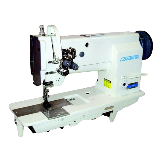
They are widely used in factories of suitcase, tent, cushion, leather goods, apparel, mat, etc.. The difference between the two models: P2339RB adopts twin-needle, two large horizontal hooks with auto lubrication. With the parts it can form ten different needle gauges. - Page 5 3.1.4 Knee control presser foot lifter installation(Fig.3) a. Installing Install Connector A , Bell Crank B , Bell C in the order shown in Fig.3. b. Adjustment (Fig.4) In the order of the following: 1.When the presser foot at its lowest posi- tion, keep the crank in the position shown by b in the figure, turn Knee Control Stop Adjusting...
- Page 6 3.1.6 Connecting the clutch lever to the pedal (Fig.6) 1)The optimum tilt angle of pedal A with floor is approx.30 degree. 2)Adjust the clutch of the motor so that clutch lever C and draw bar B run in line. 3)The machine balance wheel should rotate coun- terclockwise for normal sewing when view from opposite side of balance wheel G .
- Page 7 3.2.2 Examination Though every machine is confirmed by strict inspec- tion and test before delivery, the machine parts may be loosed or deformed after long. distance transportation with jolt. A thorough examination must be performed after cleaning the machine . Turn the balance wheel to oil mark see if there is running obstruction, parts collision, uneven resistance or abnormal nosie.
- Page 8 4. Operation 4.1 Coordination between needle, thread and sewing material Please use needle DPX¡Á 17,Nm125-180.The coarseness of needle should be in accordance with the nature of material. If stitch on heavy duty material with a slim needle, the needle will be easily bent, skip or thread clearance breakage occurs, on the contrary, stitch on tightly woven material with a very coarse needle, the material will...
- Page 9 4.3.2 Winding adjustment (Fig.15) 1) Wound bobbin thread should be neat and tight, if not , adjust the thread tension by turning tension stud thumb nut A of bobbin winder tension bracket. Note: nylon or polyester thread should be wound with light tension , otherwise bobbin D might be...
-
Page 10: Machine Adjustment
4.3.5 Placing bobbin (Fig.18) Note: when bobbin is placed into the bobbin case, thread the thread should be wound properly in the correct direction shown in the figure. 4.3.6 Drawing thread from the bobbin (Fig.19) sliding plate a. Draw the thread end to Bobbin Slot (1) shown in the figure, and pull it out down through the inner bobbin stop piece. - Page 11 b. If the needle thread is too loose and the bobbin thread is too tight, then shows as Fig. 20C, And turn the thread tension screw clockwise to increase the needle thread tension; or turn loose the bobbin lace screw to reduce the bobbin thread needle thread tension tension.
- Page 12 b. When the stop plate stops the balance wheel, more strength is needed to turn the balance wheel to reset the safety clutch device. C. Release the button in the bed. So the resetting of it is OK. (See Fig.26) stop plate 5.3.3 Regulating the strength on the safety clutch device(Fig.27)
- Page 13 5.5 Presser foot lift volume adjustment (Fig.29) when stitch on the very elastic material or the thickness of the sewing material is changed. The ad- justment should be done in the following order: crank 1. Loosen the special screw. special screw 2.
- Page 15 Parts Manual...
- Page 17 1. P2339RB Arm Parts Line Part Number Description Notes 300‐1001 Bed 200‐1003 200‐1005 GB/T117 6x30 300‐1003 Screw GB/T70.1 M10x32 200‐1009 Screw GB/T5781 M10x30 300‐1004 Trade mark 200‐1014 Screw GB827 2x5 200‐1016 Upper thread guide 200‐1017 Screw SM11/64"x40/8 200‐1018 Back cover 200‐1019 Screw SM11/64"x40/9 200‐1377 Washer 200‐1020 Cover 200‐1021 Front slide plate 200‐1022 Screw SM3/16"x32/5.4 200‐1023...
- Page 19 1. P2339RB Arm Parts Line Part Number Description Notes 200‐1049 Thread releasing plate 200‐1089 Thread releasing spring 200‐1053 Screw 200‐1055 Thread releasing moving lever 200‐1059 Screw 200‐1059 Setting plate 200‐1061 Ring GB8965 200‐1063 Thread tension plate 200‐1250 Screw 200‐1066 Spring 200‐1068 Thread tension button 200‐1069 300‐1014 Screw (long) 200‐1071 Screw 200‐1074 Small thread tension plate 200‐1075 Spring 200‐1078 200‐1080 Thread guide pin 200‐1082...
- Page 21 2. P1255RB Arm Parts Line Part Number Description Notes 200‐1002 Bed 200‐1003 200‐1005 GB/T117 6x30 200‐1007 Screw GB/T70.1 M10x25 200‐1009 Screw GB/T5781 M10x30 200‐1012 Trade mark 200‐1014 Screw GB827 2x5 200‐1016 Upper thread guide 200‐1017 Screw SM11/64"x40/8 200‐1018 Back cover 200‐1019 Screw SM11/64"x40/9 200‐1377 Washer 200‐1020 Cover 200‐1023 Thread take‐up lever guard 200‐1024 Back front cover 200‐1025 Screw 200‐1026 Lower thread finger...
- Page 23 2. P1255RB Arm Parts Line Part Number Description Notes 200‐1061 Ring GB8965 200‐1063 Thread tension plate 200‐1250 Screw 200‐1066 Spring 200‐1068 Thread tension button 200‐1069 200‐1071 Screw 200‐1074 Small thread tension plate 200‐1075 Spring 100‐1192 200‐1080 Thread guide pin 200‐1082 Thread finger 200‐1025 Screw 200‐1085 Thread releasing plate 200‐1087 Spring 200‐1088 Stopping plate 200‐1090 200‐1091 Thread tension plate 200‐1062 Thread tension pin (short) 200‐1094 Thread tension screw...
- Page 25 3. Upper Shaft Presser Foot Parts Line Part Number Description Notes 200‐1100 Upper shaft 200‐1102 Front bushing 200‐1103 Screw SM1/4"x24/13 200‐1104 Oil felt 200‐1105 Needle bar crank 200‐1107 Screw SM9/32"/28 100‐1071 Screw GB7‐1 200‐1109 Screw SM1/4"x40/7 200‐1110 Screw SM1/4"x40/4 200‐1111 Presser foot lift eccentric cam 200‐1112 Stop ring GB894.1 5 200‐1115 Slot for front crank sliding block 200‐1116 Stop ring 200‐1118 Screw SM15/64"x28/8.5 200‐1119 Screw SM15/64"x28/15...
- Page 27 4. P2339RB Needle Bar And Lower Feed Parts Line Part Number Description Notes 200‐1382 Oil wick ɸ2.5x80 200‐1383 Shaft 200‐1384 Screw SM5/16"x28/10 100‐1049 Screw SM15/64"x28/8.5 200‐1385 Oil wick ɸ2.5x240 200‐1386 Bushing 200‐1387 Thread take‐up lever 200‐1388 Sliding block 200‐1123 Screw SM15/64"x28/12 200‐1389 Oil wick ɸ3x25 200‐1390 Plug 200‐1391 200‐1392 Oil wick ɸ3x80 200‐1393 Needle bar link 200‐1394 Needle bar moving holder...
- Page 29 4. P2339RB Needle Bar And Lower Feed Parts Line Part Number Description Notes 200‐1420 Rear crank 200‐1421 200‐1422 Link 200‐1423 Screw 200‐1424 Right crank 200‐1425 200‐1426 Washer 200‐1139 200‐1427 Bushing 200‐1103 Screw 200‐1428 Collar 200‐1110 Screw SM1/4"x40/4 200‐1429 Feed crank 200‐1170 Split stop ring GB896 6 200‐1430 200‐1431 Oil wick ɸ3x55 200‐1172 Feed shaft 200‐1433 Oil felt 200‐1434...
- Page 31 5. P1255RB Needle Bar And Lower Feed Parts Line Part Number Description Notes 200‐1382 Oil wick ɸ2.5x80 200‐1383 Shaft 200‐1384 Screw SM5/16"x28/10 100‐1049 Screw SM15/64"x28/8 200‐1385 Oil wick ɸ2.5x240 200‐1386 Bushing 200‐1387 Thread take‐up lever 200‐1388 Sliding block 200‐1123 Screw SM15/64"x28/12 200‐1389 Oil wick ɸ3x25 200‐1390 Plug 200‐1391 200‐1392 Oil wick ɸ3x80 200‐1393 Needle bar link 200‐1394 Needle bar moving holder 200‐1395 Screw...
- Page 33 5. P1255RB Needle Bar And Lower Feed Parts Line Part Number Description Notes 200‐1420 Rear crank 200‐1421 200‐1422 Link 200‐1423 Screw 200‐1424 Right crank 200‐1425 200‐1426 Washer 200‐1139 200‐1427 Bushing 200‐1103 Screw 200‐1428 Collar 200‐1110 Screw SM1/4"x40/4 200‐1429 Feed crank 200‐1170 Split stop ring GB896 6 200‐1430 200‐1431 Oil wick ɸ3x55 200‐1172 Feed shaft 200‐1433 Oil felt 200‐1434 Feed connecting crank (left) 200‐1435...
- Page 35 6. P2339RB Rock Shaft And Thread Looping Parts Line Part Number Description Notes 200‐1178 Right hook saddle 200‐1179 Screw SM15/64"x28 200‐1180 Upper bushing 200‐1181 Lower bushing 200‐1182 Hook 200‐1183 Bobbin 200‐1184 Oil wick ɸ2.5x14 200‐1185 Hinge shaft 200‐1186 Screw SM3/16"32 200‐1187 Connecting lever 200‐1188 Thread finger bracket 200‐1077 Screw SM9/64"x40/4.5 200‐1377 Washer D=0.5 200‐1189 Thread finger 200‐1190 Spring washer GB7246 5...
- Page 37 6. P2339RB Rock Shaft And Thread Looping Parts Line Part Number Description Notes 200‐1206 Middle bushing 200‐1226 Rear bushing 400‐1105 Screw 200‐1202 Screw SM1/4"x40/5 200‐1227 Ball bearing 17x40x12 200‐1229 Bearing press ring 200‐1230 Screw SM9/64"x40/7 200‐1231 Oil wick 200‐1233 Feed link pin 200‐1234 Oil wick 200‐1235 Ring 200‐1232 Washer 200‐1236 Washer GB 955 5...
- Page 39 7. P1255RB Rock Shaft And Thread Looping Parts Line Part Number Description Notes 200‐1178 Right hook saddle 200‐1179 Screw SM15/64"x28 200‐1180 Upper bushing 200‐1181 Lower bushing 200‐1182 Hook 200‐1183 Bobbin 200‐1184 Oil wick ɸ2.5x14 200‐1185 Hinge shaft 200‐1186 Screw SM3/16"32 200‐1187 Connecting lever 200‐1188 Thread finger bracket 200‐1077 Screw SM9/64"x40/4.5 200‐1377 Washer 200‐1189 Thread finger 200‐1190 Spring washer GB72465 200‐1191 SM3/16"x32 200‐1192...
- Page 41 7. P1255RB Rock Shaft And Thread Looping Parts Line Part Number Description Notes 200‐1226 Rear bushing 400‐1105 Screw SM1/4"x40/4 200‐1202 Screw SM1/4"x40/5 200‐1227 Ball bearing 17x40x12 200‐1229 Bearing press ring 200‐1230 Screw SM9/64"x40/7 200‐1231 Oil wick ɸ3x18 200‐1233 Feed link pin 200‐1232 Oil wick 200‐1234 Ring 200‐1235 Washer 200‐1236 Washer GB 955 5...
- Page 43 8. Stitch Length Adjusting Parts Line Part Number Description Notes 200‐1237 Stitch length adjusting swing lever 200‐1117 Screw SM15/64"x28/8.5 200‐1239 Screw SM15/64"x28/12 200‐1240 Stitch length link 200‐1241 Eccentric shaft 200‐1242 Reverse sewing shaft 200‐1243 Reverse sewing crank 200‐1244 Screw SM15/64"x28/13 200‐1245 Screw SM15/64"x40/10.5 200‐1246 Reverse sewing lever 200‐1247 Sliding block 200‐1248 Spring washer 200‐1249 Spring holder 200‐1250 Screw SM11/64"x40/8 100‐1157 Stop pin 100‐1158 Spring 200‐1253...
- Page 45 9. Presser Foot Lift Parts Line Part Number Description Notes 200‐1300 Sliding block rail 200‐1301 Screw SM1/64"x40/12 200‐1303 Screw SM1/4"x24/16.5 200‐1304 200‐1305 Screw 200‐1306 Spring 200‐1271 Knee lifter lever 200‐1455 Adjusting screw 200‐1456 Pressure bar spring lever 200‐1468 Screw 200‐1276 Screw 200‐1278 Knee lifter crank complete 200‐1280 Knee lifter prop rod 200‐1282 Split pin 200‐1284 Stop Collar 100‐1034 Screw 200‐1287 Presser foot P1255RB 200‐1459 Set screw...
- Page 47 10. P2339RB Lubrication Parts Line Part Number Description Notes 200‐1311 Presser spring 200‐1250 Screw SM11/64"x40x8 200‐1313 Oil felt 200‐1314 oil pipe 3Dx0.5x60 200‐1315 Oil wick 200‐1316 Oil cup 200‐1317 Oil cup cover 200‐1318 Screw GB/T69 M4x16 200‐1320 200‐1321 Presser spring 200‐1322 Oil pipe 3Dx1x400 200‐1323 Oil drain pipe 5Dx1x400 200‐1324 Oil wick ɸ2.5x550 200‐1025 Screw 200‐1326 Needle bar oil return pipe 3Dx0.5x150...
- Page 49 11. P1255RB Lubrication Parts Line Part Number Description Notes 200‐1311 Presser spring 200‐1250 Screw SM11/64"x40x8 200‐1313 Oil felt 200‐1314 oil pipe 3Dx0.5x60 200‐1315 Oil wick 200‐1316 Oil cup 200‐1317 Oil cup cover 200‐1318 Screw GB/T69 M4x16 200‐1320 200‐1321 Presser spring 200‐1322 Oil pipe 3Dx1x400 200‐1323 Oil drain pipe 5Dx1x400 200‐1324 Oil wick ɸ2.5x550 200‐1025 Screw 200‐1326 Needle bar oil return pipe 3Dx0.5x150 200‐1084 Screw...
- Page 51 12. Accessories Line Part Number Description Notes 100‐1299 Parts bag 100‐1310 Hinge pin 100‐1311 Hinge pin socket 100‐1312 Cushion 100‐1313 Cushion 200‐1183 Bobbin 100‐1309 Oil pot 200‐1359 V‐belt 200‐1360 Needle 135X17#23 100‐1318 Hex key 2 GB/T5356‐1998 200‐1363 Hex key 2. 5 GB/T5356‐1998 200‐1364 Hex key 3 GB/T5356‐1998 100‐1302 Screwdriver 100‐1301 Screwdriver 100‐1300 Screwdriver 200‐1366 Cover 70x35 100‐1314...
Need help?
Do you have a question about the P2339RB and is the answer not in the manual?
Questions and answers