Table of Contents
Advertisement
Advertisement
Table of Contents

Related Manuals for Consew P1541S-CC


Summary of Contents for Consew P1541S-CC
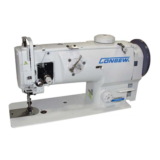
- Page 1 PREMIER SERIES P1541S-CC...
-
Page 3: Table Of Contents
CONTENT Operation Instruction 1. Brief introduction.................1 2. Main specifications................1 3. Installation...................1 4. Installing the oil box................2 5. Adjusting the tension of the belt............2 6. Installing the belt cover...............2 7. Lubrication..................3 8. Installing the needle................3 9. Threading the bobbin thread..............4 10. Installing the bobbin case..............4 11. -
Page 5: Brief Introduction
2. Main specifications 1. Brief introduction Machine adopts compound feed and special feeding Application Medium and heavy duty mechanism, which can ensure smooth feeding, Max. sewing speed 2000 s.p.m low noise, and beautiful stitch seam. It is constructed with slide link thread take-up, horizontal large rotating Max. -
Page 6: Installing The Oil Box
4. Installing the oil pot (Fig. 2) 1.Install the bolt ①, oil seal ② and spacer ③ onto the Oil reservoir oil reservoir, and then put the cushion ⑤ and spacer ⑧ into the set screw ④, then set it by nut ⑥. 2.Tighten the oil pot ⑦... -
Page 7: Lubrication
7. Lubrication (Fig.5) 1.Face plate lubrication a.Loosen the face plate screw; b.Open the face plate ① in the direction of the arrow; c.Lubricate the place as the arrow shows every day; d.Close the face plate; e.Tighten the screw. 2.Machine body lubrication a.Lubricate the place as the arrows indicate every day;... -
Page 8: Threading The Bobbin Thread
9. Threading the bobbin thread (Fig.7) 1.Insert the bobbin into the hook body, pass the thread through the thread hole ①, then pass down through the thread tension spring ②. 2.Draw the thread downward, then the bobbin will turn in the direction as the figure shows. 10. -
Page 9: Threading
13. Threading (Fig11) ① Thread in the order as shown in Fig. ② ⑨ ③ ⑧ ④ ⑩ ⑦ ⑤ ⑥ 14. Adjusting the stitch length (Fig.12) Turn the stitch length dial plate ① leftward and rightward to make the marker align with the required figure. -
Page 10: Adjusting The Thread Take-Up Spring
16. Adjusting the thread take-up spring (Fig.14) ⑤ 1.Changing the swing range of the thread take-up spring a.Loosen the set screw ②, move the stopper ③ leftward and rightward, then adjust the thread take-up spring ①. ③ b.Move the stopper rightward to increase the swing ①... -
Page 11: Adjusting The Alternating Amount Of Presser Foot
20. Adjusting the alternating amount of presser foot (Fig.18) ① When the presser foot is alternating increasingly, adjust it upward in the range of the long hole of the top feed crank ③; when the presser foot is alternating decreasingly, adjust it downward, then tighten the nut ②. -
Page 13: Parts Manual
Parts Manual... - Page 14 1. Arm and bed 13 14 45 46 20 21...
-
Page 15: Arm And Bed
1. Arm and bed Line Part Number Description Notes 400‐1001 400‐1002 400‐1003 Face plate assembly 200‐1301 Screw (1) SM11/64"X40 400‐1004 Screw (2) SM15/64"X28 400‐1005 Safe guard 400‐1006 Screw SM15/64"X28 400‐1007 Side cover (1) 400‐1008 Seal spacer 200‐1019 Screw SM11/64"X40 400‐1009 Side cover (2) 400‐1010 Screw SM11/64X40 400‐1011 Upper cover 200‐1019 Screw SM11/64"X40 400‐1012 Rubber plug 400‐1013 Small cover 200‐1019 Screw... - Page 16 2. Upper shaft and thread take-up mechanism...
-
Page 17: Upper Shaft And Thread Take-Up Mechanism
2. Upper shaft and thread take‐up mechanism Line Part Number Description Notes 400‐1038 Thread take‐up lever pin shaft 103530 100‐1049 Screw SM15/64"X28 400‐1039 Oil wick ɸ2.5X155 400‐1040 Thread take‐up lever 400‐1041 Slide block 400‐1042 Oil wick 400‐1043 Needle bar link 400‐1044 Needle bar crank pin 400‐1045 Oil wick 100‐1049 Screw SM15/64"X28 400‐1046 Needle bar crank 100‐1071 Screw SM9/32"X28 400‐1047 Screw SM9/32"X28 400‐1048 Upper shaft 400‐1049 Upper shaft front bushing 100‐1049 Screw... - Page 18 3. Needle bar vibrating parts...
-
Page 19: Needle Bar Vibrating Parts
3. Needle bar vibrating parts Line Part Number Description Notes 400‐1065 Needle bar 400‐1066 Needle bar thread guide 400‐1067 Needle 135X17#23 200‐1166 Screw SM1X8"X44 400‐1068 Needle bar adapter 400‐1069 Oil wick 400‐1070 Screw SM9X64"X40 400‐1071 Vibrating shaft 400‐1072 Crank 400‐1073 Crank pin 400‐1074 Screw GB/T80 M8X8 400‐1075 Oil felt ɸ1.5 20 400‐1076 Spring 400‐1077 Slide block 400‐1078 Vibrating shaft front bushing 400‐1079 Vibrating shaft rear bushing 400‐1080... -
Page 20: Upper Feed Parts
4. Upper feed parts 10 11... - Page 21 4. Upper feed parts Line Part Number Description Notes 400‐1091 Connecting bar 400‐1080 Oil felt 400‐1092 Connecting pin 400‐1093 Adjusting crank 400‐1094 Screw GB5781‐86 M6X22 400‐1095 Screw SM11/64"X40 400‐1096 Washer 400‐1097 SM11/64"X40 400‐1098 Upper feed shaft 400‐1099 Upper feed crank 400‐1100 Screw SM1/4"X40 400‐1101 Upper feed shaft bushing (left) 100‐1049 Screw SM15/64"X28 400‐1029 Rubber plug 400‐1102 Upper feed bushing (right) 400‐1103 Oil wick ɸ6x10 400‐1104...
- Page 22 5. Feed parts 31 32 39 40 39 40...
- Page 23 5. Feed parts Line Part Number Description Notes 400‐1140 Feed link 400‐1141 Oil felt 400‐1142 Link pin 100‐1089 Screw 400‐1143 Reverse feed bracket 400‐1144 Retaining plate 200‐1019 Screw SM11/64"X40 400‐1145 Presser plate 400‐1146 Screw SM11/64"X40 400‐1147 Reverse feed bracket shaft 100‐1049 Screw SM15/64"X40 400‐1148 Slide block 400‐1149 Feed vibrating bar assembly 400‐1150 Oil wick ɸ1.5 35 400‐1151 Screw 400‐1152 stitch length adjusting dial 400‐1153 Bolt...
-
Page 24: Lower Shaft Mechanism
6. Lower shaft mechanism 24 25 12 13... - Page 25 6. Lower shaft mechanism Line Part Number Description Notes 400‐1185 Hook CPL 100‐1250 Bobbin case CPL 400‐1186 Lower shaft 400‐1187 Lower shaft synchronized pulley CPL 400‐1058 Screw SM1/4"X40 400‐1188 Lower shaft bushing (L) 400‐1189 Lower shaft bushing (M) 400‐1190 Lower shaft bushing (R ) 400‐1191 Screw SM15/64"X28 400‐1192 Lower shaft gear 400‐1100 Screw SM1/4"X40 400‐1193 Collar 400‐1194 Screw SM11/16"X40 400‐1195 Hook driving shaft 400‐1196 Oil wick 400‐1197 Hook driving shaft bushing (L) 400‐1198 Screw...
- Page 26 7. Thread tension and bobbin thread winder mechanism...
- Page 27 7. Thread tension and bobbin thread winder mechanism Line Part Number Description Notes 400‐1236 Thread tension plate assembly 400‐1237 Thread guide plate 200‐1019 Screw SM11/64"X40 400‐1238 Thread releasing bar 400‐1239 Thread releasing bar bushing GB/T879.1 6X55 400‐1240 Bobbin thread tension assembly 400‐1241 Screw 400‐1242 Thread winder assembly 400‐1243 Friction ring 400‐1244 Screw SM11/64"X40 400‐1245 Friction wheel 100‐1089 Screw 400‐1246 Cutter 100‐1047 Screw...
- Page 28 8. Knee lifter mechanism 14 15...
-
Page 29: Knee Lifter Mechanism
8. Knee lifter mechanism Line Part Number Description Notes 400‐1247 Knee control lever support 400‐1248 Screw 400‐1249 Knee control lever support 400‐1250 Screw SM1/4"X40 400‐1251 Knee control connecting rod 400‐1252 Screw SM11/64"X40 400‐1250 Screw SM1/4"X40 400‐1253 Crank 400‐1254 Screw 400‐1255 Knee control revolving shaft 400‐1256 Spring 400‐1257 Position block 400‐1254 Screw 400‐1258 Screw GB/T77 M5X25 400‐1259 GB/T6172.1 M5 400‐1260 Screw SM9/64"X40 100‐1329... -
Page 30: Lubrication
9. Lubrication... -
Page 31: Lubrication
9. Lubrication Line Part Number Description Notes 400‐1268 Oil felt 400‐1269 Oil felt support 200‐1019 Screw SM11/64"X40 400‐1270 Small oil felt 400‐1118 Binding cord 400‐1271 Oil wick ɸ2x190 400‐1272 Press plate 400‐1273 Hook 400‐1274 Screw SM11/64"X40 400‐1275 Oil pot 400‐1276 Oil pot cover 400‐1277 Screw SM11/64"X40 400‐1278 Oil felt 400‐1279 Oil tube ɸ3x ɸ5X180 400‐1196 Oil wick ɸ2x380 400‐1280 Oil felt 1... - Page 32 10. Accessories...
-
Page 33: Accessories
10. Accessories Line Part Number Description Notes 400‐1288 Safety guard 1 400‐1289 Safety guard 2 400‐1290 Screw SM11/64"X40 400‐1291 Screw 1 SM15/64"X28 200‐1179 Screw 2 SM15/64"X28 400‐1292 Column 400‐1274 Screw SM11/64X40 400‐1293 V‐belt 200‐1368 Spool stand 100‐1309 Small oil pot 100‐1299 Parts bag 400‐1294 Spanner S=2.5mm GB/T5356‐1998 400‐1295 Spanner S=3MM GB/T5356‐1998 400‐1206 Bobbin 100‐1078 Needle 135X17#23 100‐1301...
Need help?
Do you have a question about the P1541S-CC and is the answer not in the manual?
Questions and answers