Advertisement
Table of Contents
- 1 Packing List
- 2 Hardware Bag
- 3 Assembly Instructions
- 4 General Instructions
- 5 Boom Assembly and Mast Mounting
- 6 Element Assembly and Mounting
- 7 Gamma Match Mounting
- 8 Adjusting the Standing Wave Ratio (Swr)
- 9 General Assembly
- 10 Element Assembly Details
- 11 Element Mounting Detail
- Download this manual
Advertisement
Table of Contents

Related Manuals for Maco Antennas M103C


Summary of Contents for Maco Antennas M103C
- Page 1 M1 0 3 C 3 ELEMENT 10/11 Meter Maximum Beam w w w . ma c o a n t e n n a s . n e t...
-
Page 2: Packing List
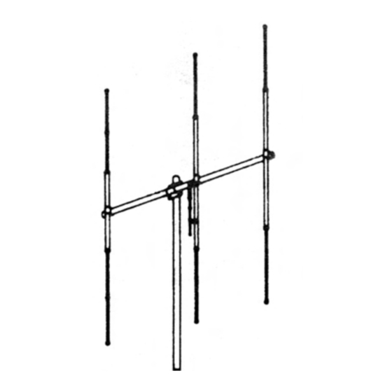
TIP SHEET Please note: In an effort to keep the price on Maco Antennas down, we have decided not to clean up all the burrs and rough edges on the parts. We recommend that you deburr and clean up each part with files, sandpaper, etc. - Page 3 GENERAL INSTRUCTIONS FIGURE 1 This drawing shows a view of the antenna assembled. The M103C may be used vertically or horizontally. These instructions and FIGURES 2 through 4 show the correct assembly instructions. It is highly recommended that rope be put in the elements to prolong their life.
- Page 4 ASSEMBLY INSTRUCTIONS (continued) FIGURE 4 GAMMA MATCH MOUNTING Mount the gamma match (GOlP) to the driven element, using the gamma straps (ZO2P, ZO8P) and attaching hardware as shown. Attach your 52 ohm coaxial cable to the connector (S42) and dress along boom and down the mast.
- Page 5 ‘4’ - 1” PLASTIC CAP PLASTIC CAP RADIATION G A M M A MA&H (SEE FIG. 4) DRIVEN ELEMENi VERTICALLY POLARIZE1 PLASTIC CAP DIRECTION DRIVEN ELEMENT PLASTIC CAP GAMMA MATC (SEE FIG. 4) HORIZONTALLY POLARIZED GENERALASSEMBLY...
- Page 6 BOOM SECTION CENTERED BETWEE U-BOLTS SADDLES, 316” NUTS &WASHERS (TYPICAL , DETAIL 2A (2) PLACES BOOM SECTION BOOM SECTION (DETAIL 2B) U02, S02, NOI, N02, SADDLES, 5/16” NUTS & W A S H E R S BOOM ASSEMBLY B O O M - T O - M A S T PLATE ATTACHED / u CUSTOMER FURNlSHEb DETAIL 28...
- Page 7 Troubleshooting Tips at the end of this instruction booklet before assembling elements. (SLOTTED END) (UNSLOTTED END) ELEMENT ASSEMBLY DETAILS ELEMENT MOUNTING DETAIL NOTE! Assemble for the middle of the desired channels, that is 27.200 for regular channel CB’s as this is channel 20. ELEMENT ASSEMBLY &...
- Page 8 S.W.R TO DETERMINE EXACT SE’l-l-INGS. THERE ARE2 SEPARATEGAh4MAADJUSTMENTS, l.CAPACI- TOR ADJUSTMENT, 2. SLIDER POSITION. DO NOT MOVE BOTH AT THE SAME TIME. MOVE THE CAPACITOR FIRST, THEN, IF NECESSARY MOVE THE SLIDER, AND GO BACK TO THE CAPACITOR. S21, Nil, N12-7 LK.
- Page 9 I n s t a l l i n g a n d r i g g i n g t o w e r s , m a s t s a n d a n t e n n a s r e q u i r e s p e c i a l i z e d s k i l l s a n d e x p e r i e n c e . I n f o r m a t i o n s u p p l i e d b y M a s s u m e s t h a t a l l p r o d u c t s w i l l b e i n s t a l l e d b y p e r s o n n e l h a v i n g t h e s e s k i l l s a n d h a v e i n s t a l l e d s i m i l a r p r o d u c t s b e f o r e .
Need help?
Do you have a question about the M103C and is the answer not in the manual?
Questions and answers