Advertisement
Quick Links
SERVICE MANUAL
-
Controller and Accessory
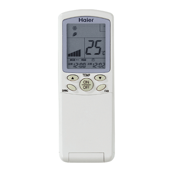
Infrared controller :
YR-H71..........Page 1
YR-H65..........Page 12
YR-H50..........Page 13
YR-H49..........Page 13
Address set controller:
ASC-002........Page 14
Wired controller:
YR-E06..........Page 15
YR-E12..........Page 24
Central controller:
YCZ-A001......Page 29
ICR01.............Page 34
IGU04.............Page 57
Advertisement


Need help?
Do you have a question about the YR-H 71 and is the answer not in the manual?
Questions and answers