Table of Contents
Advertisement
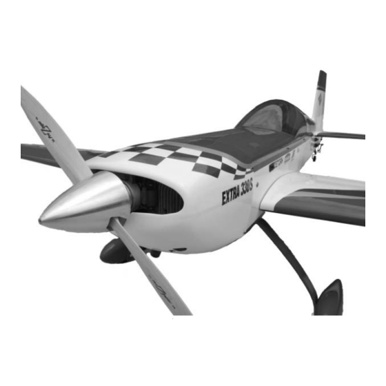
Specifications
Wingspan: .............. 97 in (2463.8mm)
Length: ................... 83 in (2108.2mm)
Wing Area: ............ 1750 sq in (112.9 sq dm)
Weight: ................... 24.75–25.5 lb (11.2 kg–11.5 kg)
Radio: ..................... 4-channel w/9 servos
Engines: ................... 3.8–4.8 cu in
WE GET PEOPLE FLYING
Extra 330S
ASSEMBLY MANUAL
• Superior controllability and aerobatic flight characteristics
• Lightweight construction
• Designed by veteran TOC competitor Mike McConville
• 90% built 1/3-scale ARF
• Plug-in wings and stabilizers for easy transport and field assembly
TM
®
Advertisement
Table of Contents

Related Manuals for Hangar 9 Extra 330S


Summary of Contents for Hangar 9 Extra 330S
- Page 1 ® WE GET PEOPLE FLYING Extra 330S ASSEMBLY MANUAL Specifications Wingspan: ....97 in (2463.8mm) Length: ....83 in (2108.2mm) Wing Area: .... 1750 sq in (112.9 sq dm) Weight: ....24.75–25.5 lb (11.2 kg–11.5 kg) Radio: ..... 4-channel w/9 servos •...
-
Page 2: Table Of Contents
Additional Required Tools and Adhesives ..........4 Optional Hangar 9 1/3 Scale Hardware Package (HAN1220, JR/HAN1221, Futaba) ....4 Servo Selection . -
Page 3: Contents Of Kit
Contents of Kit Large Parts A. Fuselage w/Hatch HAN1176 B. Right Wing Panel w/Aileron HAN1177 C. Left Wing Panel w/Aileron HAN1178 D. Right Stabilizer w/Elevator HAN1179 E. Left Stabilizer w/Elevator HAN1180 F. Rudder HAN1181 G. Canopy HAN1182 H. Painted Cowl HAN1184 I. -
Page 4: Additional Required Tools And Adhesives
• Square • Covering Iron (HAN101) • Syringe • Dental floss or string • Tap handle • Toothpicks Optional Hangar 9 ® 1/3 Scale Hardware Package (HAN1220, JR/HAN1221, Futaba) • 3 " Wheels (2) (DUB350L) • Tail Wheel Assembly with Hardware (OHI130) •... -
Page 5: Servo Selection
Servo Selection The servos used for the control surfaces of the Extra 330S must have a minimum of 80 ounce inch of servo torque. In the prototype Extras, we used JR8411 servos. Before Starting Assembly Before beginning the assembly of the Extra 330S, remove each part from its bag for inspection. Closely inspect the fuselage, wing panels, rudder, and stabilizer for damage. -
Page 6: Section 1 - Aileron Servo Installation
Section 1 – Aileron Servo Installation Required Parts Step 3 Tie a weight to a piece of string. A wheel collar works • Wing panel (right and left) great in this application. Lower the string into the Required Tools and Adhesives wing from the aileron servo opening. - Page 7 Section 1 – Aileron Servo Installation Step 4 Insert the servo with the 24" extension towards the tip of the wing. Use the string to pull the servo lead through the wing. Position the servo so the output shaft is towards the trailing edge of the wing. Use a 1/16”...
-
Page 8: Section 2 - Aileron Control Horn Installation
• 8-32 x 2" Hangar 9 ® control horn screw (4) (Included in HAN1220 (JR™) or HAN1221 (FUT)) • Hangar 9 control horn A-nut (4) (Included in HAN1220 (JR™) or HAN1221 (FUT)) Step 1 Tape the aileron to the wing. Make a mark 1/2"... - Page 9 Mix a small amount of 30-minute epoxy and lightly coat the inside of the tapped hole and the 8-32 x 2" Hangar 9 control horn screw. From the top of the aileron, screw the 8-32 x 2" into the tapped hole and securely tighten.
-
Page 10: Section 3 - Hinging And Sealing The Control Surfaces
The of 30-minute epoxy in order to achieve good Hangar 9 ® Extra 330S control surfaces are predrilled glue joint penetration. If you notice the epoxy to use Robart’s Super Hinge Points. becoming thicker, then mix a new batch! - Page 11 Section 3 – Hinging and Sealing the Control Surfaces Step 3 Step 5 Allow the epoxy to fully cure for at least 6 hours. Carefully attach the aileron to the wing, making sure When cured, work each hinge throughout its full the hinges are inserted in their respective hinge motion several times using your hands.
-
Page 12: Section 4 - Sealing The Hinge Gaps
Section 3 – Hinging and Sealing the Control Surfaces Step 7 When fully cured, move each control surface throughout its travel range several times to break away any epoxy in the hinge. Be sure to deflect the surface fully. Section 4 – Sealing the Hinge Gaps Required Parts Step 1 Cut a piece of Clear UltraCote (not included) for... - Page 13 Section 4 – Sealing the Hinge Gaps Step 2 Step 4 Using a ruler, measure 1/2" from the folded crease Mark and cut the folded covering to an overall length and mark two places with a felt-tipped pen. of 40". This piece will be inserted and ironed down into the hinge bevel on the bottom of the aileron.
-
Page 14: Section 5 - Aileron Linkage Installation
• Phillips screwdriver (small) as to which way to turn the linkage to lengthen • Threadlock or shorten the link. Hangar 9 also offers a Pro-Link™ Wrench (HAN3558) to make adjustments easier. MatchBox Option: To simplify the installation of the aileron servo linkages, you may want to use the JR™... - Page 15 Section 5 – Aileron Linkage Installation Step 4 Attach the linkage to the servo horn on the aileron. Adjust the link so the aileron is centered at the same time as the servo. Photo for Step 4 Step 5 Repeat Steps 1 through 4 for the second servo. Step 6 Repeat Steps 1 through 5 for the remaining servos in the opposite wing panel.
-
Page 16: Section 6 - Wing Tube Installation
Section 6 – Wing Tube Installation Required Parts Step 2 Carefully slide the remaining wing panel onto the • Wing panels • Fuselage wing tube that projects from the fuselage. The fit • Wing tube may be tight; use caution when inserting the wing •... -
Page 17: Section 7 - Rudder And Elevator Servo Installation
Section 7 – Rudder and Elevator Servo Installation Required Parts Step 2 Install the servos in the fuselage tail section with the • Fuselage output shaft to the rear as shown in the photo. If Required Tools and Adhesives using a non-computer radio, be sure to install one of •... -
Page 18: Section 8 - Elevator Linkage Installation
Mix a small amount of 30-minute epoxy and lightly coat the inside of the threaded holes and the Step 1 8-32 x 2" Hangar 9 ® screw. From the top of the To properly locate the position of the control horn elevator, thread the 8-32 screws into the tapped on the bottom of the elevator, measure inward 1"... - Page 19 Section 8 – Elevator Linkage Installation Step 6 Step 8 Cut off the first section of two of the hinges. This is Insert the longer tube into the aft hole in the fuselage. done to clear the tube installed in the elevator. Measure the distance of the exposed tube and adjust until both side are equal.
- Page 20 Section 8 – Elevator Linkage Installation Step 10 Step 11 Remove the tube and install it into one stabilizer half- Install the shorter tube into the stabilizer half with way up to the first line on the tube. Drill through the the secured tube.
-
Page 21: Section 9 - Rudder Linkage Installation
Using the 4-40 screws and nuts included in the Screw a 4-40 ball link 5 to 6 turns onto a 4 " long Hangar 9 ® package, attach the ball link to the outer 4-40 linkage. Screw the opposite end of the linkage hole in the arm. - Page 22 Section 9 – Rudder Linkage Installation Step 2 Step 6 Using a 5/32" drill bit and drill press, carefully drill Measure the width of the rudder. Divide the a 5/32" hole through the rudder perpendicular (90°) measurement by 2 and make marks on either side to the rudder centerline at the marked position.
- Page 23 Step 13 Using the 4-40 screws and nuts included in the Hangar 9® package, attach the ball link to the outer hole in the arm. The correct sequence is 4-40 screw, ball link, standoff, servo arm and 4-40 nut. Be sure Step 10 to use threadlock.
-
Page 24: Section 10 - Landing Gear Installation
Section 10 – Landing Gear Installation Required Parts Step 3 Press the landing gear fairing into position to transfer • Fuselage • Landing gear fairing the location of the bolt heads into the foam. Use a • 10-32 x 1" socket head bolt (4) hobby knife to remove the foam to provide clearance •... -
Page 25: Section 11 - Wheel Pant Installation
Section 11 – Wheel Pant Installation Required Parts Step 3 • Wheel (2) • 3/16" wheel collar (4) Use a rotary tool or drill to make a 1/2" hole at the location made in the last step. • #4 washer (2) •... - Page 26 Section 11 – Wheel Pant Installation Step 5 Step 7 Remove the pant and use a 9/64" drill bit to drill the Secure the pant in place using a 4-40 x 1/2" socket location marked in the previous step. head screw, #4 lock washer, and #4 washer. Use threadlock on the screw to prevent it from coming loose in flight.
-
Page 27: Section 12 - Tail Wheel Installation
Section 12 – Tail Wheel Installation Required Parts Step 4 Use two #6 x 3/4" sheet metal screws to secure the • Fuselage • Tail wheel assembly tail wheel bracket in place. A hardwood plate is Required Tools and Adhesives positioned in the rear of the fuselage, allowing these •... -
Page 28: Section 13 - Receiver, Battery And Fuel Tank Installation
Section 13 – Receiver, Battery and Fuel Tank Installation Required Parts Step 3 Use foam and rubber bands (or Velcro® straps) to • Fuselage secure the receiver to the battery tray. Required Tools and Adhesives Note: We have also mounted MatchBoxes •... - Page 29 Section 13 – Receiver, Battery and Fuel Tank Installation Step 6 Step 8 Assemble the tank per the instructions included with Mount the receiver switch in a convenient location in the tank. Be sure to use the gas-compatible stopper the side of the fuselage. and fuel tubing.
-
Page 30: Section 14 - Mounting The Engine And Cowl
Cut the opening for the The Hangar 9 ® Extra 330S accepts gas engines throttle servo in the top of the engine box. The servo ranging from 60 through 80cc. The prototype Extras is located 2 "... - Page 31 Section 14 – Mounting the Engine and Cowl Step 3 G62 Installation Make up the throttle linkage using a 4-40 rod and Step 1 two ball links. Carefully tap the throttle arm of the carburetor with a 4-40 tap and connect the ball link Remove the metal engine mount (if attached) from to the throttle arm.
- Page 32 Section 14 – Mounting the Engine and Cowl Step 3 Completing the Engine Installation Mount the throttle servo on the bottom of the engine Step 1 box 3/4" back from the front edge of the box. Use the hardware supplied with the servo to attach the servo Run the fuel lines from the pick up in the tank to to the engine box.
-
Page 33: Section 15 - Hatch Assembly
Section 15 – Hatch Assembly Required Parts Step 3 Install a 1/3-scale pilot figure to the hatch using • Hatch • Canopy Shoo Goo or similar adhesive that will remain • 4-40 x 1/2" screw (4) • #4 washer (4) flexible. -
Page 34: Section 16 - Balancing The Model
Step 5 Step 6 Lightly sand the inside edge of the canopy and Apply a bead of RCZ56 Canopy Glue (ZINJ5007) slightly inside the line drawn on the hatch using around the inside edge of the canopy. Position the medium sandpaper. canopy onto the hatch. -
Page 35: Section 18 - Control Throws
Section 17 – Radio Setup A 7-channel or greater computer radio is highly With a 6-channel computer radio, it will be necessary recommended. This allows the following features: to Y-harness the two rudder and elevator servos; a reversed elevator servo is needed to achieve the •... -
Page 36: Preflight At The Field
Setup and Flying by Mike McConville Seal the aileron and elevator hinge gaps. Our new Extra 330S will blow away almost any pilot wanting to fly aerobatics. When designing this This should be considered part of finishing the... - Page 37 The Prototype Model Setup I found that adequate engine cooling is very important with the GT80 and strongly recommend All of the recommended settings in this manual adding the cowl baffles and cutting the cowl bottom are a result of the flight testing on the prototype hole to the size recommended in the instructions.
- Page 38 “act” linear throughout the entire throttle stick models, snaps are different, particularly on the new movement. I also use this at times to make the breed of aerobatic birds like the Extra 330S, which throttle response less sensitive in the rpm ranges have large control surfaces.
-
Page 39: Extra 330S-3D At Its Best
“flying” the snaps, but I’ll bet you’ll see a big improvement in the quality of your flying. Extra 330S-3D at its Best and spins, it seems like the aerobatic options are 3D maneuvers (in simplest terms) are maneuvers endless. - Page 40 The Blender Setup: Follow the 3D setup as described in the manual. Be sure to use Expo. Setting the CG toward What it is: The Blender or Panic maneuver is a the aft location will help, but I have had great results vertical diving roll that virtually stops its descent as it even at the forward CG location.
- Page 41 Setup: Same as the Blender, only for this one, flip the switch to turn on the spoilerons. This will help to keep the Extra 330S from teetering back and forth. How it’s done: At near stall airspeed up high, slowly feed in up elevator until you have the full 3D rate up in it.
- Page 42 Trickiest Part: Keeping up with the model if it The Harrier begins to wobble. What is it: It is very slow forward flight in a very nose high (about 45 degrees) attitude. Recovery: Simply add full power and reduce elevator to transition into normal forward flight. Setup: Same as the Elevator, and the raised ailerons help in this maneuver even more.
- Page 43 How it’s done: Fly low along the ground at low throttle and gently add power with up elevator to What it is: The Extra 330S “hovers” vertically in bring the model into a vertical position. Add throttle place, rotating left around its roll axis.
- Page 44 As soon as the model is diving straight down at low throttle, add full up-elevator. If you do it right, the Extra 330S will instantly transition from a vertical dive to an Elevator. Tip: Add a little throttle just after transition to an Elevator.
- Page 45 Wall, then transition into a Torque Roll over the runway. Practice all of this stuff up high before you try that. I hope you enjoy your Extra 330S as much as I do! Happy Landings! Mike McConville Setup: Same as the Elevator, and the raised ailerons help in this maneuver too.
-
Page 46: 2003 Official Ama National Model Aircraft Safety Code
2003 Official AMA National Model Aircraft Safety Code Effective January 1, 2003 Model Flying MUST be in accordance with this Code in order for AMA Liability Protection to apply. GENERAL 7) I will not operate models with pyrotechnics (any device that explodes, burns, or propels a projectile of any kind) 1) I will not fly my model aircraft in sanctioned events, air including, but not limited to, rockets, explosive bombs... - Page 47 2003 Official AMA National Model Aircraft Safety Code Continued 4) I will operate my model using only radio control Organized RC Racing Event frequencies currently allowed by the Federal 10) An RC racing event, whether or not an AMA Rule Communications Commission.
- Page 48 ® WE GET PEOPLE FLYING © 2003, Horizon Hobby, Inc. 4105 Fieldstone Road Champaign, Illinois 61822 (877) 504-0233 www.horizonhobby.com #6061...
Need help?
Do you have a question about the Extra 330S and is the answer not in the manual?
Questions and answers