Pfaff 487 Service Manual
Hide thumbs
Also See for 487:
- Instruction manual (44 pages) ,
- Adjustment manual (44 pages) ,
- Service manual (36 pages)
Table of Contents
Advertisement
Quick Links
Advertisement
Table of Contents

Related Manuals for Pfaff 487


Summary of Contents for Pfaff 487
- Page 1 Service manual 296-12-17 454 Justieranleitung engl. 06.99...
- Page 2 The reprinting, copying or translation of PFAFF instruction manuals, whether in whole or in part, is only permitted with our previous consent and with written reference to the source. G.M. PFAFF Aktiengesellschaft Postfach 3020 D-67653 Kaiserslautern Königstr. 154 D-67655 Kaiserslautern...
-
Page 3: Table Of Contents
Contents Contents ................Chapter - Page Safety ......................... 1 - 1 General notes on safety ..................... Safety symbols ......................1 - 2 Danger warnings ......................1 - 2 Adjustments ......................2 - 1 Notes on adjustment ....................2 - 1 Tools, gauges and other equipment ................ -
Page 4: Safety
Safety Safety General notes on safety The machine must only be operated by adequately trained operators and only when the instruction manual has been fully read and understood! All notices on safety and the instruction manual of the motor manufacturer are to be read before the machine is put into operation! All notes on the machine concerning danger and safety must be observed! The machine must be used for the purpose for which it is intended and must not be... -
Page 5: Safety Symbols
Safety Safety symbols Danger! Special points to observe. Danger of injury to operating or technical staff! Danger warnings Never put your hands in the sewing area during sewing! Danger of injury by the needle! While setting or adjusting the machine do not leave any objects on the table nor in the needle plate area! Objects may be trapped or flung out of the machine! To adjust this mechanism the machine must be tilted backwards. -
Page 6: Adjustments
Do not use a screw-clamp on the needle bar of the PFAFF 487, because this will damage the special coating of the needle bar. Notes on adjustment All adjustments in this service manual refer to a fully assembled machine. -
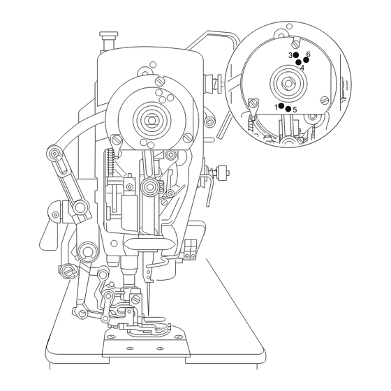
Page 9: Checking And Adjusting Aid
Adjustment Checking and adjusting aid By blocking holes 1 to 6 with a pin it is possible to accurately fix the required needle bar positions. Fig. 2 - 01 Turn the balance wheel until the needle bar is roughly in the required position. Insert the blocking pin in the required hole and press against it. -
Page 10: Preliminary Adjustment Of Needle Height
Adjustment Preliminary adjustment of needle height Requirement With the needle bar at b.d.c. the underside of the needle bar must be at a distance of approx. 16.5 mm from the needle plate. 16,5 mm Fig. 2 - 02 Re-position needle bar 1 (screws 2) according to Requirement. 2 - 3... -
Page 11: Needle In Needle-Hole Centre
Adjustment Needle in needle-hole centre Requirement The needle must enter exactly in the centre of the needle hole. Fig. 2 - 03 Set the needle immediately above the needle hole. Loosen screws 1, 2 and 3. Reposition needle bar frame 4 according to the Requirement both crosswise and lengthwise of the feeding direction. -
Page 12: Neutral Position Of Drop Feed
Adjustment Neutral position of drop feed Adjustment with the gearcase closed 08.01 Requirement At stitch length setting "O" the drop feed must not make any feeding movement when the balance wheel is turned. Fig. 2 - 04 Set feed regulator lever 1 in its lowest position. Turn bush 2 (screw 3) so that mark 4 is facing downwards and the edge of the milled surface is at an angle of approx. - Page 13 Adjustment Adjustment with the gearcase opened .08.02 Fig. 2 - 05 Set feed regulator lever 1 in its lowest position. Turn bush 2 (screw 3) so that mark 4 is facing downwards and the edge of the milled surface is at an angle of approx. 45° to the front side of the machine. (For the final adjustment, see Chapter 2.20 "Top feed synchronization".) Turn crank 5 (screw 6) according to Requirement.
-
Page 14: Actuating Lever Under The Reverse-Feed Control
Adjustment Actuating lever under the reverse-feed control Requirement At the longest stitch length setting, reverse-feed control lever 3 must have a slight play (approx. 0.3 mm) when pressed lightly. Fig. 2 - 06 Loosen screws 1 and 2. Make sure that reverse-feed control lever 3 is resting on stop 4, move actuating lever 5 lightly against the reverse-feed control and tighten screw 1 again. -
Page 15: Feeding Motion Of Drop Feed
Adjustment Feeding motion of drop feed Requirement At the longest stitch length setting and with the needle bar in position 0.6 past t.d.c. (blocking hole 1) the feed dog must not move when the reverse-feed control is operated. Fig. 2 - 07 Turn feed eccentric 1 (screws 2) according to Requirement. -
Page 16: Lifting Motion Of Drop Feed
Adjustment Lifting motion of drop feed Requirement At stitch length setting "0" and with the needle bar in position 0.6 past t.d.c. (blocking hole 1) the feed dog must be at t.d.c. The cutout in lifting eccentric 1 must face roughly vertically downwards. Fig. -
Page 17: Height Of Drop Feed Dog
Adjustment Height of drop feed dog Requirement At stitch length setting "0" and with the needle bar in position 0.6 mm past t.d.c. (blocking hole 1) the feed dog must: 1. be centred in the feed slots of the needle plate both crosswise and lengthwise, 2. -
Page 18: Clearance Between Presser Foot And Needle Plate
Adjustment Clearance between presser foot and needle plate Requirement When lifting lever 1 is raised there must be a clearance of 5 mm between the presser foot and the needle plate. Fig. 2 - 10 Lower presser foot onto needle plate using lifting lever 1. Reduce pressure on the presser bar by unscrewing regulating screw 2 (knurled nut 3). -
Page 19: Top Feed Actuating Link
Adjustment Top feed actuating link Requirement 1. All moving parts of the top feed must move freely but without any play. 2. The vibrating presser must not contact the lifting presser. Fig. 2 - 11 Lower the presser foot using lifting lever 1. Loosen screw 2. - Page 20 Adjustment Neutral position of top feed Requirement With the stitch length and top feed set at "0" and with adjustment link 9 9 9 9 9 fitted, drive lever 2 2 2 2 2 must not make any movement when the balance wheel is turned. 19 3 Fig.
- Page 21 Adjustment Set feed regulator levers 6, 7 and 8 at "0". Fit adjustment link 9 onto pins 10. Rotate the balance wheel and turn crank 11 (screw 12) so that the vibrating presser no longer moves. Loosen nut 13. Move linkage 14 up and down several times, and while doing so adjust lever 16 (screw 15) so that the vibrating presser no longer moves.
- Page 22 Adjustment Feeding motion of vibrating presser Requirement At the longest stitch length setting and with the needle bar in position 0.6 past t.d.c. (blocking hole 1) the vibrating presser must not move when the reverse-feed control is operated. Fig. 2 - 14 Raise the presser foot.
-
Page 23: Vibrating Presser Clearance
Adjustment Vibrating presser clearance Requirement At stitch length setting "0", when the presser foot is resting on the needle plate and the vibrating presser is at top dead centre, the clearance between vibrating presser and needle plate must be as follows, depending on the top-feed type: 1.3 mm for pulling-type top feed 3.2 mm for pushing-type top feed For sewing thin materials the top-feed stroke on machines with pushing-type... -
Page 24: Top Feed Lifting Motion
Adjustment Top feed lifting motion Requirement With the stitch length set at "2" (on version "N" at stitch length "5") the lifting presser must rest on the bottom feed dog (see arrow) when the rising bottom feed dog has reached the upper surface of the needle plate. -
Page 25: Position Of Lifting Presser
Adjustment Position of lifting presser Requirement When the bottom feed dog is at t.d.c. the lifting presser must be parallel with the drop feed dog. Fig. 2 - 17 Turn eccentric pin 1 (screw 2) according to Requirement. 2 - 18... -
Page 26: Synchronizing The Top Feed
Adjustment Synchronizing the top feed Requirement When the feed regulator levers for stitch length and top-feed stroke are set at "3", both top feed and bottom feed must move at the same stroke when the balance wheel is turned. Fig. 2 - 18 Press the reverse-feed lever and loosen nut 1 accessible behind it. -
Page 27: Stitch Length Alignment
Adjustment Stitch length alignment Requirement When the stitch length is set at "3" the feed stroke must be the same in forwards and reverse feeding Fig. 2 - 19 Turn bush 1 (screw 2) according to Requirement. Make sure that the eccentricity of bush 1 faces downwards. -
Page 28: Eccentric Hook Shaft Bearing
Adjustment Eccentric hook shaft bearing Requirement 1. The slot in bearing 3 must be visible from the underside. There must be a very slight, but still perceivable, play between gears 5 and 7. 2. When the hook is resting lightly against thrower 4 and the hook point is at the needle centre, there must be a clearance of less than 0.1 mm between hook point and clearance cut. -
Page 29: Final Adjustment Of Needle Rise, Needle Height, And Bobbin Case Position Finger
Adjustment Final adjustment of needle rise, needle height, and bobbin case position finger Requirement With the stitch length set at "0" and the needle bar in position 1.8 mm past b.d.c. (adjustment hole "4") 1. the hook point must be at the needle centre and the top of the needle eye 0.8 mm below the hook point, and 2. -
Page 30: Bobbin Case Opener Height
Adjustment Bobbin case opener height Requirement When bobbin case opener 3 is at its left reversal point the top side of its finger must be 0.5 mm above the lower edge of bobbin case trip 4. 0,5 mm Fig. 2 - 22 Turn bobbin case opener bearing 1 (screws 2) according to Requirement. -
Page 31: Position Of Bobbin Case Opener
Adjustment Position of bobbin case opener Requirement When bobbin case opener 3 3 3 3 3 is in its far left position 1. the front edge of its finger must be 0.6 mm 0.6 mm 0.6 mm 0.6 mm behind the front edge of bobbin case trip 7 7 7 7 7 ; 0.6 mm 2. -
Page 32: Bobbin Case Opener Motion
Adjustment Bobbin case opener motion Requirement When the needle bar is in position 1.8 mm past b.d.c. (adjustment hole "4"), bobbin case opener 3 must be in its far right position. Fig. 2 - 24 Adjust bobbin case opener eccentric 1 (screws 2) according to Requirement. 2 - 25... -
Page 33: Needle Thread Tension Release
Adjustment Needle thread tension release Requirement When presser bar lifter 3 is raised, the tension disks must be at least 0.5 mm apart. 0,5 mm Fig. 2 - 25 Adjust tension release lever 1 (screw 2) according to Requirement. Lower the presser foot onto the needle plate; the tension must now be fully activated. 2 - 26... -
Page 34: Thread Check Spring And Thread Regulator
Adjustment Thread check spring and thread regulator Requirement 1. The stroke of thread check spring 3 must be completed when the needle point enters the material (spring stroke roughly 7 mm). 2. Thread regulator 4 must be fixed in its elongated hole so that thread check spring 3 has moved by about 1 mm when the hook has widened the thread loop to its maximum. -
Page 35: Bobbin Winder
Adjustment Bobbin winder Requirement 1. When the bobbin winder is engaged the winder spindle must be driven reliably, but when it is disengaged, friction wheel 5 must not rest against drive wheel 1. 2. The bobbin winder must switch itself off when the amount of thread wound is about 1 mm from the edge of the bobbin. -
Page 36: Knee Lever Resting Position
Adjustment Knee lever resting position Requirement When in its resting position, knee lever linkage 2 must be roughly at right angles to the bedplate. Fig. 2 - 28 Raise the presser foot using the presser bar lifter Fit knee-lever coupling 1 on the knee-lever shaft and snap linkage 2 into knee lever coupling 1. -
Page 37: Knee Lever Play
Adjustment Knee lever play Requirement When the presser foot is resting on the needle plate there must be a clearance of about 1.3 mm between lifting lever 3 and lifting piece 4. 1,3 mm Fig. 2 - 29 Set needle bar at b.d.c. and lower presser foot onto needle plate. Turn crank 1 (screws 2) according to Requirement. -
Page 38: Knee Lever Stroke Limitation
Adjustment Knee lever stroke limitation Requirement When the knee lever is fully pressed, there must be a clearance as indicated below between presser foot and needle plate, and the presser bar lifter must drop down by its own weight. Model A and Subclass -731/..: 7 mm 7 mm 7 mm 7 mm... -
Page 39: Position Of Vibrating Presser In Relation To Lifting Presser
Adjustment Position of vibrating presser in relation to lifting presser Requirement When the presser foot is raised with the presser bar lifter and the take-up lever is in its highest position, the teeth of vibrating presser 3 must not be protrude below the shoe of lifting presser 4. -
Page 40: Pressure Of The Vibrating- And Lifting Pressers
Adjustment Pressure of the vibrating- and lifting pressers Requirement Even at the highest sewing speed the material must still be fed reliably, but there must not be any pressure marks on the material. 12 mm Fig. 2 - 32 Set regulating screw 1 for the pressure of the vibrating presser flush with the top surface of the housing. -
Page 41: Stitch Length Limitation
Adjustment Stitch length limitation Fig. 2 - 33 Loosen or, depending on the amount of limitation, take out screw 1 (accessible through the fitting window). Set feed regulator lever 2 to the required maximum stitch length. Place limitation stop 3 onto regulator lever 3 and secure it with screw 1 in the top or bottom hole (depending on the amount of limitation). - Page 42 G.M. PFAFF Aktiengesellschaft Postfach 3020 D-67653 Kaiserslautern Königstr. 154 D-67655 Kaiserslautern Telefon: (0631) 200-0 Telefax: (0631) 172 02 Internet: www.PFAFF.de Gedruckt in der BRD Printed in Germany Imprimé en R.F.A. Impreso en la R.F.A.
Need help?
Do you have a question about the 487 and is the answer not in the manual?
Questions and answers