Pfaff 487 Instruction Manual
Industrial
Hide thumbs
Also See for 487:
- Adjustment manual (44 pages) ,
- Service manual (42 pages) ,
- Instruction manual (42 pages)

Related Manuals for Pfaff 487


Summary of Contents for Pfaff 487
-
Page 1: Instruction Manual
® Industrial INSTRUCTION MANUAL This instruction manual applies to machines from the following serial numbers onwards: # 2 756 862 296-12-18 645/002 Betriebsanleitung engl. 06.09... - Page 2 As an alternative to the internet download the adjustment manual can also be ordered in book form under part no. 296-12-18 646/002. The reprinting, copying or translation of PFAFF Instruction Manuals, whether in whole or in part, is only permitted with our previous authorization and with written reference to the source.
-
Page 3: Table Of Contents
.05.02 Specialist personnel....................... 7 Danger warnings........................8 Proper use ..........................9 Specifications ........................10 PFAFF 487..........................10 Versions and subclasses ...................... 10 Disposal of Machine ......................11 Transportation, packing and storage ................12 Transportation to customer‘s premises ................12 Transportation inside the customer‘s premises..............12 Disposal of packing materials .................... - Page 4 Index Contents ..................Page .01.06 Fitting the synchronizer ......................22 .01.07 Fitting the reel stand ......................22 Connecting the plug-in connections and earth cables ............23 Commissioning the machine ....................24 Switching the machine on/off ....................24 Basic position of the machine drive unit ................25 Setting up ...........................
-
Page 5: Safety
Sicherheit Safety Directives This machine is constructed in accordance with the European regulations contained in the conformity and manufacturer’s declarations. In addition to this Instruction Manual, also observe all generally accepted, statutory and other regulations and legal requirements and all valid environmental protection regulations! The regionally valid regulations of the social insurance society for occupational accidents or other supervisory organizations are to be strictly adhered to! General notes on safety... -
Page 6: Safety Symbols
It is the obligation of the user to ensure that none of the safety mechanisms are removed ● or deactivated. It is the obligation of the user to ensure that only authorized persons operate and work ● on the machine. Further information can be obtained from your PFAFF agent. -
Page 7: Operating And Specialist Personnel
Sicherheit Operating and specialist personnel Operating personnel .05.01 Operating personnel are persons responsible for the equipping, operating and cleaning of the machine as well as for taking care of problems arising in the sewing area. The operating personnel is required to observe the following points and must: always observe the Notes on Safety in the Instruction Manual! ●... -
Page 8: Danger Warnings
Sicherheit Danger warnings A working area of 1 m must be kept free both in front of and behind the machi- ne, so that easy access is possible at all times. Never put your hands or fingers in the sewing area during sewing! Danger of injury by the needle! While setting or adjusting the machine do not leave any objects on the table nor in the needle plate area! Objects may be trapped or flung out of the machine! -
Page 9: Proper Use
Proper use Proper use The PFAFF 487 is an ultra-high-speed sewing machine with variable top feed. The machine is used for sewing lockstitch seams in industry. Any and all uses of this machine which have not been approved of by the... -
Page 10: Specifications
Max. stitch length: Version B:........................4,5 mm Max. speed 487..........................5000 min 487-918/........................4200 min Motor data: .................see motor specification plate Noise data: Emission sound level at workplace at a speed of 4000 spm: ....... L = 79.0 dB(A) ■... -
Page 11: Disposal Of Machine
Disposal of Machine Disposal of Machine Proper disposal of the machine is the responsibility of the customer. ● The materials used for the machine are steel, aluminium, brass and various plastic ● materials. The electrical equipment comprises plastic materials and copper. The machine is to be disposed of according to the locally valid pollution control regula-ti- ●... -
Page 12: Transportation, Packing And Storage
Transportation, packing and storage Transportation, packing and storage Transportation to customer‘s premises The machines are delivered completely packed. Transportation inside the customer‘s premises The manufacturer cannot be made liable for transportation inside the customer‘s premises nor to other operating locations. It must be ensured that the machines are only transported in an upright position. -
Page 13: Explanation Of Symbols
Explanation of symbols Explanation of symbols In this instruction manual, work to be carried out or important information is accentuated by symbols. These symbols have the following meanings: Note, information Cleaning, care Lubrication Maintenance, repairs, adjustment, service work (only to be carried out by technical staff) -
Page 14: Controls
Controls Controls On/off switch The power supply to the machine is swit- ● ched on or off by turning switch 1. Fig. 7 - 01 Keys on the machine head As long as key 1 is pressed during sew- ● ing, the machine sews in reverse. -
Page 15: Raising The Presser Foot
Controls Raising the presser foot Fig. 7 - 03 Fig. 7 - 03a Knee switch (only on sub-class -918/14) By operating knee switch 1 the machine ● changes from one of two pre-set fullness settings to the other. Fig. 7 - 04... -
Page 16: Pedal
Controls Pedal With the on/off switch on ● = Machine stop +1 = Sew - 1 = Raise presser foot (for machines with -911/97) - 2 = Trim thread (for machines with -900/..) Fig. 7 - 05 Stitch length adjustment lever / reverse sewing To adjust the stitch length, press lever ●... -
Page 17: Top Feed Adjustment Lever
Controls Top feed adjustment lever Adjustment levers 1 and 2 are used to ● adjust the top feed stroke (also see Chap- ter 9.06 Adjusting the top feed). Fig. 7 - 07 Edge trimmer -731/11 Do not touch the running mo- tor! Danger of injury! By pressing or raising key 1, the edge ●... -
Page 18: Control Panel (Only On Machines With Quick-Eco Drive)
Controls Control panel (only on machines with Quick-Eco drive) The description can be found in the separate instruction manual for the control panel. Operating elements for the programmable fullness control The description for programmable fullness control can be found in the separate instruction manual. -
Page 19: Installation And Commissioning
Installation and commissioning Installation and commissioning The machine must only be mounted and commissioned by qualified personnel! All relevant safety regulations are to be observed! If the machine is delivered without a table, it must be ensured that the frame and the table top which you intend to use can hold the weight of the machine and the motor. -
Page 20: Assembling The Motor (Only On Machines With Quick-Motor)
Installation and commissioning Assembling the motor .01.02 (only on machines with Quick-motor) 109-001 Fig. 8 - 02 Assemble motor mounting 1, motor 2, belt guard support 3 and belt pulley 4 as shown in ● Fig. 8-02. Tightening the V-belt .01.03 Fit the V-belt. -
Page 21: Mounting The Bottom V-Belt Guard
Installation and commissioning Mounting the bottom V-belt guard .01.04 109-07 Fig. 8 - 04 Loosen screws 2 and adjust belt guard support 1 so that the motor pulley and V-belt run ● freely. Tighten screws 2 and fasten belt guard 3 with screw 4. ●... -
Page 22: Fitting The Synchronizer
Installation and commissioning Fitting the synchronizer .01.06 Insert position stop 1 in the machine ● case and fasten it with screw 2. Place synchronizer 3 on the shaft so that ● stop 1 is in the slot of synchronizer 3, see arrow. -
Page 23: Connecting The Plug-In Connections And Earth Cables
Installation and commissioning Connecting the plug-in connections and earth cables Fig. 8 - 08 Connect all plugs as labelled to the control box . ● Screw the earth cable from the sewing head and the main switch to earth point A. ●... -
Page 24: Commissioning The Machine
Installation and commissioning Commissioning the machine Check the machine, especially the electri- ● cal leads, for any damage. Remove pin 1 of the oil reservoir 2 ● (Fig. 8 - 09). The pin serves only to protect the machine from damage during transport and must not be used when sewing. -
Page 25: Basic Position Of The Machine Drive Unit
Installation and commissioning Basic position of the machine drive unit (only on machines with Quick-EcoDrive and control unit P40ED) Switch on the machine. ● Press the TE/speed key twice to select the input mode. ● Select parameter "798" by pressing the corresponding +/- key, and select service level ●... -
Page 26: Setting Up
Setting up Setting up All instructions and regulations in this instruction manual must be observed. Special attention must be given to all safety regulations! All setting-up work must only be done by personnel with the necessary train- ing. For all setting-up work the machine must be isolated from its power supply by turning off the on/off switch or removing the machine plug from the electric power socket! Inserting the needle... -
Page 27: Winding The Bobbin Thread, Adjusting The Thread Tension
Setting up Winding the bobbin thread, adjusting the thread tension Fig. 9 - 02 Place an empty bobbin 1 onto bobbin shaft 2. ● Thread the bobbin in accordance with Fig. 9-02 and wind it anti-clockwise around bobbin ● 1 a few times. Switch on the bobbin winder while at the same time pressing bobbin winder spindle 2 ●... -
Page 28: Removing / Inserting The Bobbin Case
Setting up Removing / Inserting the bobbin case Switch off the machine! Danger of injury due to uninten- tional starting of the machine! Removing the bobbin case: Tilt back the machine. ● Raise latch 1 and remove bobbin case 2. ●... -
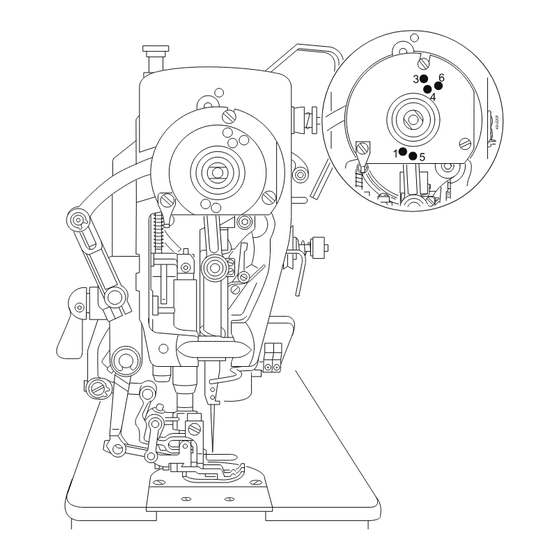
Page 29: Threading The Needle Thread / Adjusting The Needle Thread Tension
Setting up Threading the needle thread / Adjusting the needle thread tension Fig. 9 - 05 Switch off the machine! Danger of injury due to unintentional starting of the machine! Thread the machine as shown in Fig. 9-05. ● Adjust the needle thread tension by turning disk 1. ●... -
Page 30: Adjusting The Top Feed
Setting up Adjusting the top feed Fig. 9 - 06 Fig. 9 - 06 c Standard sewing Set lever 1 and 2 at the same value. The ● top and bottom feed dogs operate with the same feed stroke (see Fig. 9-06a). Top fullness Set lever 1 at a higher value than lever 2. -
Page 31: Adjusting The Stitch Counter For The Bobbin Thread Control
Setting up Adjusting the stitch counter for the bobbin thread control (only on machines (only on machines with Quick Motor and control unit P40 (ED) ) Please see the description in the separate control panel instruction manual. werden. -
Page 32: Wartung Und Pflege
Care and maintenance Wartung und Pflege Wartungsintervalle Clean the hook compartment .......Daily, several times if in continuous use Check the oil level ............Daily, before starting the machine Clean/lubricate the hinges on the top feed dog ..........Once a week Check/adjust the air pressure ......... Daily, before starting the machine Clean the filter of the air filter/lubricator ............ -
Page 33: Oil Level Of The Machine
Only use oil with a medium vis- cosity of 22.0 mm²/s at 40° C and a density of 0.865 g/cm³ at 15°C! We recommend PFAFF sewing-machine oil, part No. 280-1-120 144. Fig. 10- 02 Cleaning/lubricating the top feed joints Once a week or after the machine has ●... -
Page 34: Checking/Regulating The Air Pressure
Care and maintenance Checking/regulating the air pressure Check the air pressure on gauge 1 every ● time before operation. Gauge 1 must show a pressure of 6 bar. ● Regulate this pressure if required. ● To do so, pull knob 2 up and turn it accor- ●... -
Page 35: Parameter Settings
Care and maintenance Parameter settings (only on machines with Quick-EcoDrive and control unit P40 ED) The selection of the user level and the alteration of parameters is described in the sepa- ● rate instruction manual for the drive unit. Parameter list .07 .01 Speed for start backtackl B, C... -
Page 36: Mounting The Table Top And Circuit Diagrams
Mounting the table top Table top cutout... -
Page 37: Mounting The Table Top
Mounting the table top Mounting the table top (with Quick-EcoDrive and control unit P40 ED) 91-268 703-95... -
Page 38: Circuit Diagrams
Circuit diagram Circuit diagrams Reference list for the Circuit diagrams 91-191 501-95 .03.01 Control unit Quick P40 ED Control panel BDF S2 Sewing head recognition system (OTE) Sewing lamp (optional) LED stitch counter Sewing motor Main switch Manual backtacking key S1.1 Pedal speed control unit Start inhibitor (E6 stop) -
Page 39: Circuit Diagrams 91-191 501-95
91-191 501-95 Circuit diagram Part 1 Version 07 .07 .06 Circuit diagrams 91-191 501-95 .03.02... - Page 40 Circuit diagram 91-191 501-95 Version 07 .07 .06 Part 2...
- Page 41 91-191 501-95 Circuit diagram Part 3 Version 07 .07 .06...
-
Page 42: Wearing Parts
A detailed parts list for the complete machine is included with the accessories. In case of loss, the parts list can be downloaded from the internet address www.pfaff-industrial.com/pfaff/de/service/downloads As an alternative to the internet download the parts lists can also be ordered in book form under part no. - Page 43 Wearing parts Subclass -731/.. Trimming margin Partnumber 5,0 mm 91-169 395-04/001 7 ,0 mm 91-169 395-04/002 9,0 mm 91-169 395-04/003 Subclass -900/.. 91-171 850-91 91-165 505-05 1-108 087-15 91-171 854-15 91-171 853-15 11-108 084-15 (2x) 91-108 222-15 99-137 151-45 91-171 049-05 95-774 464-05 91-700 996-15...
- Page 44 PFAFF Industriesysteme und Maschinen AG Hans-Geiger-Str. 12 - IG Nord D-67661 Kaiserslautern Phone: +49 - 631 200-0 Fax: +49 - 631 17202 E-mail: info@pfaff-industrial.com Hotlines: Technical service: +49 - 175/2243-101 Application consultance: +49 - 175/2243-102 Spare-parts hotline: +49 - 175/2243-103...
Need help?
Do you have a question about the 487 and is the answer not in the manual?
Questions and answers