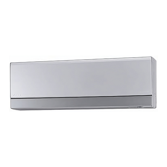
Daikin FTXG25EV1BS Installation Manual
Inverter r410a split series
Hide thumbs
Also See for FTXG25EV1BS:
- Service manual (355 pages) ,
- Operation manual (32 pages) ,
- Technical data manual (12 pages)
Table of Contents
Advertisement
INSTALLATION
MANUAL
R410A Split Series
Models
FTXG25EV1BW FTXG25EV1BS
FTXG35EV1BW FTXG35EV1BS
CTXG50EV1BW CTXG50EV1BS
ATXG25EV1B
ATXG35EV1B
ATXG50EV1B
Installationsanleitung
Split-Baureihe R410A
Manuel d'installation
Montagehandleiding
R410A Split-systeem
Manual de instalación
Manuale d'installazione
Serie Multiambienti R410A
Εγχειρßδιο εγκατÜστασηò
διαιροýìενηò σειρÜò R410A
Manual de Instalação
Рóêоводство по монтажó
Серия R410A с раздельной óстановêой
Installation manual
English
R410A Split series
Deutsch
Français
Série split R410A
Nederlands
Español
Serie Split R410A
Italiano
ΕλληνικÜ
Portugues
Série split R410A
Рóссêий
Montaj kýlavuzlarý
Türkçe
R410A Split serisi
Advertisement
Table of Contents

Summary of Contents for Daikin FTXG25EV1BS
- Page 1 Montagehandleiding Nederlands R410A Split-systeem Manual de instalación Español Serie Split R410A Manuale d’installazione Italiano Serie Multiambienti R410A Models FTXG25EV1BW FTXG25EV1BS Εγχειρßδιο εγκατÜστασηò ΕλληνικÜ διαιροýìενηò σειρÜò R410A FTXG35EV1BW FTXG35EV1BS Manual de Instalação CTXG50EV1BW CTXG50EV1BS Portugues Série split R410A ATXG25EV1B Рóêоводство по монтажó...
- Page 2 2SB63475-2A...
-
Page 3: Safety Precautions
Safety Precautions • Read these Safety Precautions carefully to ensure correct installation. • This manual classifies the precautions into WARNING and CAUTION. Be sure to follow all the precautions below: they are all important for ensuring safety. WARNING....Failure to follow any of WARNING is likely to result in such grave consequences as death or serious injury. CAUTION....Failure to follow any of CAUTION may in some cases result in grave consequences. -
Page 4: Choosing A Site
Accessories – Indoor unit Mounting plate Remote controller holder Operation manual Titanium Apatite Photocatalytic AAA dry-cell batteries Installation manual Air-Purifying Filter Indoor unit fixing screws Wireless remote controller (M4 × 12L) Choosing a Site • Before choosing the installation site, obtain user approval. Indoor unit •... -
Page 5: Installation Tips
Installation Tips How to remove and attach the front panel • Removing the panel 1) Place one finger on the panel tab on either side of the front panel and open it until it is horizontal. 2) Sliding the front panel to the left will cause the revolving axis on the right to come off. -
Page 6: How To Set The Different Addresses
How to open the indoor unit service lid • Opening the lid When removing from the side of the indoor unit 1) Push and slide the service lid in the direction of the arrow. 2) Disengage the tabs. 3) Slide the other tab in the direction of the arrow. Tabs Tabs (2) When removing from the bottom of the indoor unit... -
Page 7: Indoor Unit Installation Drawings
Indoor Unit Installation Drawings Installing and removing the indoor unit Screws (Field supply) A Mounting plate Mounting Attaching the indoor unit plate 1) Using the 2 marks on top of the indoor unit, attach the mounting plate hooks onto the indoor unit. 2) Attach the tabs on the bottom frame firmly onto the mounting plate. -
Page 8: Indoor Unit Installation
Indoor Unit Installation Installing the mounting plate • The mounting plate should be installed on a wall which can support the weight of the indoor unit. 1) Temporarily secure the mounting plate to the wall, make sure that the panel is completely level, and mark the boring points on the wall. -
Page 9: Installing Interunit Wiring
Indoor Unit Installation Installing interunit wiring 1) Remove the service lid from the front grill. Attach the 2) Take off the electric parts box service lid. indoor unit 3) After attaching the mounting plate, connect the interunit wiring as shown hooks. - Page 10 6) Wrap the insulation on the piping with insulating tape. If you are not replacing the drain hose, store it in the location shown below. NOTE: 1. When fixing the indoor unit screws, use an Indoor unit fixing screw (M4 × 12L). (In one place on the left side or the right side.) 7) Store any excess power cord behind the indoor unit.
-
Page 11: When Connecting To An Ha System
Indoor Unit Installation When connecting to an HA system 1) Remove the front grille. (5 screws) 2) Remove the metal plate electric parts box cover. (6 tabs) 3) Insert the connection cord to the HA connector “S21”. 4) Lay the connecting cord as shown in the figure below. 5) Restore the electric parts box cover and the front grill. -
Page 12: Refrigerant Piping Work
Refrigerant Piping Work Flaring the pipe end (Cut exactly at 1) Cut the pipe end with a pipe cutter. right angles.) Remove burrs 2) Remove burrs with the cut surface facing downward Flaring so that the chips do not enter the pipe. Set exactly at the position shown below. -
Page 13: Selection Of Copper And Heat Insulation Materials
Refrigerant Piping Work 2-2. Selection of Copper and Heat Insulation materials • When using commercial copper pipes and fittings, observe the Inter-unit wiring following: Gas pipe 1) Insulation material: Polyethylene foam Liquid pipe Heat transfer rate: 0.041 to 0.052W/mK (0.035 to 0.045kcal/mh°C) Refrigerant gas pipe’s surface temperature reaches 110°C max. -
Page 14: Trial Operation And Testing
Trial Operation and Testing Trial operation and testing 1-1 Measure the supply voltage and make sure that it falls in the specified range. 1-2 Make sure the front panel opens and closes smoothly using remote controller. (Do not do this using the indoor unit operation/stop button.) 1-3 Trial operation should be carried out in either cooling or heating mode. - Page 15 3P166464-1 M05B043 (0511) HT...


Need help?
Do you have a question about the FTXG25EV1BS and is the answer not in the manual?
Questions and answers