Table of Contents
Advertisement
Quick Links
Safety, Operation & Maintenance Manual
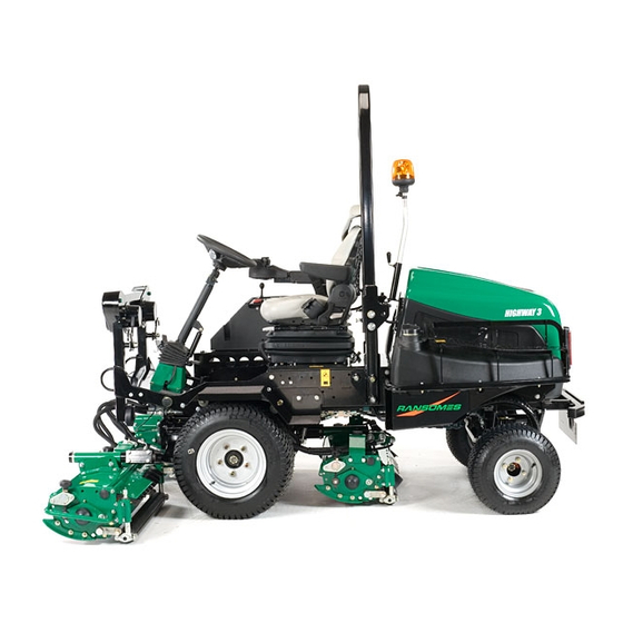
Ransomes Highway 3™ Ride on Reel Mower
Highway 3 - 4 Wheel Drive
Series: GF
Product code: LGEA340
Highway 3 - 2 Wheel Drive
Series: GU
Product code: LGEA320
WARNING: If incorrectly used this machine can cause severe
injury. Those who use and maintain this machine should be
trained in its proper use, warned of its dangers and should
read the entire manual before attempting to set up, operate,
adjust or service the machine.
GB
United
Kingdom
RJL 100 January 2013
WARNING
®
24881G-GB (rev.1)
Advertisement
Table of Contents
Troubleshooting

Related Manuals for Ransomes Highway 3


Summary of Contents for Ransomes Highway 3
- Page 1 24881G-GB (rev.1) ® Safety, Operation & Maintenance Manual Ransomes Highway 3™ Ride on Reel Mower Highway 3 - 4 Wheel Drive Series: GF Product code: LGEA340 Highway 3 - 2 Wheel Drive Series: GU Product code: LGEA320 WARNING WARNING: If incorrectly used this machine can cause severe injury.
- Page 2 Ransomes Jacobsen Limited reserves the right to make design changes without obligation to make these changes on units previously sold and the information contained in this manual is subject to change without notice. © 2013, Ransomes Jacobsen Limited. All Rights Reserved...
-
Page 3: Table Of Contents
1 CONTENTS SECTIONPAGE SECTIONPAGE MOWING ..............47 INTRODUCTION ..............2 TO STOP THE ENGINE ..........47 IMPORTANT PRODUCT IDENTIFICATION ........3 7.10 ........47 UNBLOCKING CUTTING UNITS GUIDELINES FOR THE DISPOSAL OF SCRAP 7.11 .............48 BACKLAPPING PRODUCTS ............. 4 7.11 ........50 RANSPORTING ON A TRAILER 2.3.1 DURING SERVICE LIFE ......... -
Page 4: Introduction
INTRODUCTION 2.1 IMPORTANT _________________________________________________________ The Ransomes Highway 3 is a diesel powered self propelled reel mower. Using hydraulic systems for traction drive, cutting unit lift and lower, cutting unit drives and steering. IMPORTANT: This is a precision machine and the service obtained from it depends on the way it is operated and maintained. -
Page 5: Product Identification
2 INTRODUCTION 2.2 PRODUCT IDENTIFICATION ___________________________________________ West Road Maximum front axle load in Kg (for machines being Ransomes Europark Ipswich IP3 9TT driven on the highway) England Gross weight (mass) in Kg Maximum rear axle load in Kg (for machines being driven... -
Page 6: Guidelines For The Disposal Of Scrap Products
‘General waste’ area. • Do not incinerate waste. Finally update machinery records to indicate that the machine has been taken out of service and scrapped. Provide this serial number to Ransomes Jacobsen Warranty department to close off relevant records. en-4... -
Page 7: Parts Manual
2 INTRODUCTION 2.4 PARTS MANUAL ___________________________________________________ As part of the ISO14001 principles and in the era of free electronic media, Ransomes Jacobsen Limited no longer sends a paper parts manual with every product. If you wish to refer to a parts list for this mower you have four options from which to choose: Website –... -
Page 8: Safety
It is essential all safety labels are kept legible, if they are missing or illegible they must be replaced. If any part of the machine is replaced and it originally carried a safety label, a new label must be affixed to the replacement part. New safety labels are obtainable from Ransomes Jacobsen dealers. 3.1.3 STARTING THE ENGINE •... -
Page 9: Transporting
3 SAFETY INSTRUCTIONS • After striking a foreign object Inspect the lawnmower for damage and make repairs before restarting and operating the equipment. • If the machine starts to vibrate abnormally, check immediately. 3.1.5 TRANSPORTING • Ensure that the cutting units are securely fastened in the transport position. Do not transport with cutting mechanism rotating. - Page 10 SAFETY INSTRUCTIONS governor settings or overspeed the engine. Operating the engine at excessive speed may increase the hazard of personal injury. • When refuelling, STOP THE ENGINE, DO NOT SMOKE. Add fuel before starting the engine, never add fuel while the engine is running. •...
- Page 11 98/37/EC Sections 3.2.2, Seating & 3.4.3, Be Given By A Qualified Person Prior To Rollover. Using The Machine For The First Time. Ransomes Jacobsen Limited Recommends That A Local Risk Assessment Is Completed By The Owner/ WARNING User Of The Machine To Determine Any...
-
Page 12: Specifications
SPECIFICATION 4.1 DIMENSIONS & WEIGHTS Width of Cut: 215 cm Overall Width Cutting: 240.5 cm Overall Width Transport (minimum): 137 cm Overall Height with ROPS Frame up: 211 cm Overall Height with ROPS Frame down: 142 cm Overall Length: 255 cm Length with ROPS Frame Down, Add: 7 cm Weight of 2 WD Machine, Hydraulic &... - Page 13 BKT LG-306 6pr 1.00 - 1.37 bar 18.50 x 8.50 - 8 BKT LG-306 4pr 1.00 - 1.37 bar Highway 3 BKT Armaturf 6 BKT Armaturf 6 23 x 10.50 - 12 1.00 - 1.37 bar 18.50 x 8.50 - 8 1.00 - 1.37 bar...
-
Page 14: Machine Specification
SPECIFICATION 4.2 MACHINE SPECIFICATION ______________________________________________ Frame construction: Heavy duty formed steel chassis with box section frame rails. Cutting unit drive: Fixed displacement hydraulic motors. Transmission: Four wheel drive on demand. Direct coupled variable displacement pump to direct coupled 200cc/rev front, 160cc/rev rear wheel motor. Speeds: Cutting: 0 - 12 km/h Forward... -
Page 15: Vibration Level
Information Supplied for Physical Agents Directive 2002/44/EC By reference to: Hand/Arm Standards: BS EN ISO 5349-1 (2001) BS EN ISO 5349-2 (2001) Max. LH or RH Ransomes Highway 3 Accelerations m/s² Series GF & GU Hand / Arm Acceleration Mean Value of X, Y, Z Aeq Level 0.39 ±... -
Page 16: Cutting Unit Specification
SPECIFICATION 4.6 CUTTING UNIT SPECIFICATION __________________________________________ Sport 200 Sport 200 Sport 200 Construction Heavy duty welded pressed steel construction Reel Length 762mm 762mm 762mm Number of Knives Reel Diameter (New) 197mm 197mm 197mm Minimum Reel Diameter (Before Replacement) 178mm 178mm 178mm Fixed Head Height of Cut (Standard Blade) 12.7mm - 89mm... -
Page 17: Engine Specification
4 SPECIFICATION 4.9 ENGINE SPECIFICATION ________________________________________________ Model: D1105-T-E3B-RNUK-3 Vertical, water-cooled, 4-cycle Type: diesel engine Number of Cylinders Bore & Stroke 78mm x 78.4mm Total Displacement 1123cm³ Combustion Chamber Spherical type (E-TVCS) Intake System Turbo charged Gross Intermittent Power 24.5kW @ 3000rpm Maximum Speed: 3150 ±... -
Page 18: Certificates Of Conformity
Machine Name Název stroje Maskinnavn Machinenaam Masina nimi Laitteen nimi Nom de la machine Maschinenbezeichnung Ransomes Highway 3, (4WD) Gépnév Denominazione della macchina Iek rtas nosaukums Mašinos pavadinimas Isem tal-Magna Nazwa urz dzenia Nome da Máquina Ransomes Highway 3, (2WD) Numele echipamentului Názov stroja Naziv stroja Nombre de la máquina Maskinens namn Heiti tækis Maskinnavn... - Page 19 A nyilatkozat kelte (hely és id ) Luogo e data della dichiarazione Deklar cijas vieta un datums Deklaracijos vieta ir data Il-post u d-data tad-dikjarazzjoni West Road, Ransomes Europark, Miejsce i data wystawienia deklaracji Local e data da declaração Locul i data declara iei Miesto a dátum vyhlásenia Kraj in datum izjave Lugar y fecha de la declaración Ipswich, England, IP3 9TT Plats och datum för deklarationen Tæknistaðlar og tæknilýsingar sem notaðar eru Benyttede tekniske standarder og spesifikasjoner Staður og dagsetning yfirlýsingar...
- Page 20 Business name and full address of the manufacturer Bedrijfsnaam en volledig adres van de fabrikant Ransomes Jacobsen Limited vollständige Adresse des Herstellers West Road, Ransomes Europark, Ipswich, England, IP3 9TT endereço completo do fabricante empresa y dirección completa del fabricante Description and identification of the partly completed machinery.
- Page 21 These accessories have been designed La quasi-macchina non deve essere messa in servizio finché la macchina finale in cui deve essere incorporata non è stata dichiarata conforme, nel caso, alle disposizioni della Direttiva to be fitted to the Ransomes Highway 3 - 2006/42/CE.
-
Page 22: Decals
DECALS 5.1 SAFETY DECALS EC __________________________________________________ 4146857 4153197 en-20... - Page 23 5 DECALS 009034910 Read Operator's Manual. 009034890 Keep a Safe Distance from the Machine. 009034920 Stay Clear of Hot Surfaces. 009034880 Do Not Open or Remove Safety Shields While the Engine is Running. 009034940 Caution Rotating Blades. 009034930 Avoid Fluid Escaping Under Pressure. Read Operators Manual for Service Procedures. 009034900 Do Not Remove Safety Shields While Engine is Running.
-
Page 24: Instruction Decals Ec
DECALS 5.2 INSTRUCTION DECALS EC ____________________________________________ en-22... - Page 25 5 DECALS Description Maximum Sound Power Level Parking Brake Power socket 12V Transport - Mow Throttle Reel rotation Backlap Ignition Switch Foot Pedal Forward - Reverse Horn Steering Wheel Tilt Lubrication Point Read Manual Indicator Stalk Functions Jacking Point Hooking Point en-23...
-
Page 26: Controls
CONTROLS OPERATOR WORKSTATION _______________________________________ 6.10 en-24... -
Page 27: Instrument Panel
6 CONTROLS INSTRUMENT PANEL_____________________________________________ Starter Key Switch Right hand Unit Lift/Lower Throttle Control Lever Centre Unit Lift/Lower Parking Brake Switch Left hand Unit Lift/Lower Hazard Warning Switch PTO engaged Cutter Switch Right hand cutting unit in cutting position. Backlap Centre cutting unit in cutting position. 4 WD in Reverse Left hand cutting unit in cutting position Visual Display... -
Page 28: Starter Key Switch
CONTROLS 6.2A STARTER KEY SWITCH __________________________________________ The starter key (A) should be turned clockwise to the 'start' position to start the engine. After starting, the key should be released and allowed to return automatically to the 'on' position for normal running. NOTE:The glow plugs will auto pre-heat depending on the coolant temperature before cranking begins. -
Page 29: D Hazard Warning Switch
6 CONTROLS 6.2D HAZARD WARNING SWITCH_______________________________________ Switches the hazard warning indicators on and off. The red lens flashes when switched on. 6.2E CUTTING UNIT SWITCH (PTO) _____________________________________ To commence cutting ensure speed limiter is in mow position and the units have been lowered. Push bottom of the rocker switch and move joystick towards the lower position. -
Page 30: H Visual Display
CONTROLS 6.2H VISUAL DISPLAY ________________________________________________ Is activated when the ignition is switched on. 6.2H.1 START UP SCREEN ______________________________________________ Upon initial power up this screen will be shown. The hour meter will show total engine running hours. 1234.5 6.2H.2 WARNING/SERVICE SCREEN ______________________________________ After the start up screen the following warning screen will be applied, it will remain in view for a few seconds, if the machine is within 5 hours of the next service interval a... -
Page 31: Start Up Slope Warning Screen
6 CONTROLS 6.2H.3 START UP SLOPE WARNING SCREEN ______________________________ When the ignition switch is turned to crank one of the following screens will be shown. If the machine is fitted with the slope monitoring system the screen will display the logo “TST™” (Tilt Sensor Technology) and maximum working slope symbol. -
Page 32: Main Run Screen
CONTROLS 6.2H.4 MAIN RUN SCREEN ______________________________________________ The main run screen will give the operator all the information he needs to operate the machine, it should not require any operator in- put to view standard data whilst using the mower. If any error presents itself whilst the operator has navigated away from this screen, it should instantly return to this screen. -
Page 33: Water Temperature Screen
6 CONTROLS 6.2H.5 WATER TEMPERATURE SCREEN __________________________________ If the temperature increases to 108°C, the RED LEDs (A) flash at a rate of two flashes every four seconds. The warning buzzer will sound at the same rate and the “CLEAR BUGSCREEN” warning replaces the centre icons and flashes. -
Page 34: Slope Warning Screens
CONTROLS 6.2H.7 SLOPE WARNING SCREENS_______________________________________ NOTE Slope warning screens will only appear when TST is installed. During work if the machine is driven onto a slope of 16º 16° the screen will display this warning which over rides all other information, and will continue until the machine has been driven to an area of less than 16º... -
Page 35: Main Menu
6 CONTROLS 6.2H.8 MAIN MENU ____________________________________________________ The tick can be moved up and down using buttons 2 and 3; button 4 then enters the selected page. Button 1 returns to the main menu. There will be three options within this menu: Main Menu CLOCK Clock... -
Page 36: Service Menu
CONTROLS 6.2H.10 SERVICE MENU _________________________________________________ The tick can be moved up and down using buttons 2 and 3; button 4 then enters the selected page. Button 1 returns to the main menu. There will be three options within this menu: Fault Log Time to Service Diagnostics... -
Page 37: Datalogging Menu
6 CONTROLS 6.2H.11 DATALOGGING MENU____________________________________________ The last 50 “Faults” that the controller detects will be recorded, once 50 faults are logged, the next fault arising will overwrite the oldest fault. This information will be retrieved using the service tool, 12/05/2008 or can be seen on the errors page of the service menu. -
Page 38: J Right Hand Unit Lift/Lower Switch
CONTROLS NOTE: THE OPERATOR MUST BE SEATED TO ENABLE LIFT / LOWER FUNCTIONS. 6.2J RIGHT HAND UNIT LIFT/LOWER SWITCH ____________________________ To lower the cutting unit move the switch lever forward. To raise the cutting unit move the switch lever rearwards NOTE: If the PTO is engaged when the unit is lowered the green led will illuminate when the... -
Page 39: L Left Hand Unit Lift/Lower Switch
6 CONTROLS 6.2L LEFT HAND UNIT LIFT/LOWER SWITCH _____________________________ To lower the cutting unit move the switch lever forward. To raise the cutting unit move the switch lever rearwards NOTE: The Yellow PTO LED will illuminate when the PTO is selected. The Green LED indicates the unit is below 400mm, therefore with both are illuminated the reel will be rotating. -
Page 40: Traction Pedal
CONTROLS TRACTION PEDAL _______________________________________________ 1. Forward Travel (Traction Pedal A) Press the front of pedal down for forward travel. To slow and stop - Gently return the FWD/REV foot pedal to the neutral position. Do not press traction pedal when parking brake is on. -
Page 41: Horn
6 CONTROLS HORN _________________________________________________________ For machines without the lighting kit. The horn button (A) is situated on the foot plate. If the lighting kit is fitted the horn is located on the end of the indicator stalk. POWER OUTLET ________________________________________________ The Auxiliary Power Outlet is situated on the right hand side of the seat on the seat plate. -
Page 42: Parking Brake Release Valve
CONTROLS PARKING BRAKE RELEASE VALVE ________________________________ The Parking Brake Release Valve is situated under the seat plate, on the right hand chassis plate. It is used to release the parking brake when the engine is not running The Parking brake can be released by rotating the handwheel (A) fully clockwise after releasing lock wheel (B) and using the hand pump (C) to create sufficient pressure... -
Page 43: Lighting Kit (Optional)
6 CONTROLS 6.10 LIGHTING KIT (Optional)___________________________________________ Lighting control Stalk Push away from operator to turn main beam on. Pull towards operator to flash headlights. Move stalk up to indicate right turn. Move stalk down to indicate left turn. Push stalk in to sound horn. NOTE: Side lights will operate when ignition is in the run position When the lighting kit is fitted a brake light function is... -
Page 44: Operation
OPERATION 7.1 DAILY INSPECTION ____________________________________________________ CAUTION The Daily Inspection Should Be Performed Only When The Engine Is Off And All Fluids Are Cold. Lower Implements To The Ground, Engage Parking Brake, Stop Engine And Remove Ignition Key. Perform a visual inspection of the entire unit, look for signs of wear, loose hardware and missing or damaged components. -
Page 45: Operator Presence And Safety Interlock System
7 OPERATION 7.2 OPERATOR PRESENCE AND SAFETY INTERLOCK SYSTEM _________________ The operator presence & safety interlock system prevents the engine from starting unless the parking brake is on, and the mowing device is switched off. The system stops the engine if the operator leaves the seat with the parking brake disengaged. -
Page 46: Operating Procedure
OPERATION 7.3 OPERATING PROCEDURE _____________________________________________ Under no circumstances should the engine be started without the operator seated on the tractor. CAUTION To Help Prevent Injury, Always Wear Safety Glasses, Leather Work Shoes Or Boots, A Hard Hat And Ear Protection. Do not operate tractor or attachments with loose, damaged or missing components. -
Page 47: Fitting The Cutting Unit To The Machine
7 OPERATION WARNING DO NOT USE ON SLOPES GREATER THAN 13° UNLESS “TST™” IS INSTALLED Under no circumstances should the engine be started without the operator seated on the tractor. 10. Do not operate tractor or attachments with loose, damaged or missing components. 7.4 FITTING THE CUTTING UNIT TO THE MACHINE_____________________________ Front Cutting Units With the lift arms (A) in the lower position align... -
Page 48: Operation Of The Machine
OPERATION 7.5 OPERATION OF THE MACHINE _________________________________________ Read the Safety Instructions. BEFORE OPERATING FOR THE FIRST TIME • Check and adjust tyre pressure, if necessary, see section 4.2 Specification. • Add diesel fuel to tank if necessary. • Check engine oil and top-up, if necessary. •... -
Page 49: Mowing
7 OPERATION • Do not move pedal suddenly–always operate slowly and smoothly. Never move pedal violently from forward to reverse or vice versa. • Always keep foot firmly on the foot pedal–a too relaxed foot control may result in a jerky motion. 7.8 MOWING _____________________________________________________________ Release the transport latches and lower the cutting units with the joysticks. -
Page 50: Backlapping
• Backlapping should only be carried out by trained staff. • Ransomes Jacobsen recommend that grinding paste is only applied to the reel when it is stationery, the engine is off and the parking brake applied. • When applying grinding paste the reel should only be rotated by appropriately sized piece of wood and not by hand. - Page 51 7 OPERATION PROCCEDURE Apply an even coat of backlapping compound to the entire length of each blade of the reel. Turn the Reel Speed Control valve counterclockwise (C) see section 6.8 Reel Speed Control to allow reels to rotate at there slowest speed. Set the backlap switch (A) see section 6.2F to the backlap position .
-
Page 52: Transporting On A Trailer
OPERATION 7.12 TRANSPORTING ON A TRAILER ________________________________________ The machine is fitted with tie-down loops front (A) on hard point and rear (B). Always tie down the machine securely to the trailer. Always follow any recommendations for maximum trailer weights given in your towing vehicles handbook. Never exceed the maximum gross weight shown on the trailer plate. -
Page 53: Mowing On Slopes
7 OPERATION 7.14 MOWING ON SLOPES __________________________________________________ The mower has been designed for good traction and stability under normal mowing conditions. Use caution when operating on slopes, especially when the grass is wet. Wet grass reduces traction and steering control. WARNING To Minimize The Possibility Of Overturning, The Safest Method For Operating On Hills... - Page 54 That A Seat Belt Must Be Worn With A Rops To Comply With The Machiney Directive 2006/42/EC Sections 3.2.2, Seating & 3.4.3, Rollover Ransomes Jacobsen Limited A = Maximum Allowable Slope Recommends That A Local Risk Assessment Is Completed By The Owner/User Of The...
- Page 55 7 OPERATION SLOPE CALCULATION CHART Use Either of these columns but not both The result of what you are measuring Height ‘C’ in inches Height ‘C’ in millimeters Slope Angle ‘D’ Slope Angle ‘D’ measured with a 1 yard measured with a 1 metre measured in measured in horizontal edge ‘A’...
-
Page 56: Maintenance And Lubrication
MAINTENANCE & LUBRICATION 8.1MAINTENANCE & LUBRICATION CHART ___________________________________ MAINTENANCE AND LUBRICATION CHART Interval Item Section First 50 hours Change Engine Oil Check Fan Belt Tension Change Hydraulic Filter Daily Check Engine Oil Level. 10 hours Check Safety Interlock System. - Page 57 8 MAINTENANCE & LUBRICATION en-55...
-
Page 58: Engine Lubrication
MAINTENANCE & LUBRICATION 8.2 ENGINE LUBRICATION ________________________________________________ Check Engine Oil Level Check the engine oil level before starting or more than five minutes after stopping the engine. With the machine on level ground, remove the dipstick D, wipe it clean and replace. Take the dipstick D out again, and check the oil level. -
Page 59: Engine: Fan Belt
8 MAINTENANCE & LUBRICATION 8.3 ENGINE: FAN BELT ____________________________________________________ Check & Adjust Fan Belt. The fan belt is adjusted so that it has sufficient tension to avoid undue stress on alternator bearings but does not slip on the alternator pulley. Use the following procedure to check the belt tension at the mid-point of the belt between crank shaft and alternator pulleys. -
Page 60: Engine Coolant
MAINTENANCE & LUBRICATION 8.4 ENGINE COOLANT ____________________________________________________ Check Engine Coolant Level The level of coolant in the expansion tank should be between the MAX and MIN level indicators when cold. If topping up is required, remove the plastic cap and top up using the correct anti-freeze mixture, see section 8.1. -
Page 61: Hydraulic System
8 MAINTENANCE & LUBRICATION 8.5 HYDRAULIC SYSTEM __________________________________________________ Check Hydraulic Oil Level Check hydraulic oil level using sight gauge (C). Change Hydraulic Oil (a) Clean around hose (A) in bottom of Hydraulic tank and remove. (b) Allow tank to drain into a suitable container and replace hose. -
Page 62: Hydraulic Test Ports
MAINTENANCE & LUBRICATION 8.6 HYDRAULIC TEST PORTS _____________________________________________ If any problems are experienced with the hydraulic system service ports are provided to enable pressures to be checked. All tests, unless stated otherwise, should be carried out with the hydraulic oil at normal working temperature. TEST PORTS Transmission pressure: 250 bar forward / reverse. -
Page 63: Fuel System
8 MAINTENANCE & LUBRICATION 8.7 FUEL SYSTEM ________________________________________________________ Use Diesel fuel No.2-D (ASTM D975) Bleeding air from fuel system (a) Turn the ignition switch to the ON position (don't start engine). (b) Open air vent (B) on Fuel filter housing to allow air to escape. -
Page 64: Air Cleaner
MAINTENANCE & LUBRICATION 8.8 AIR CLEANER________________________________________________________ Cleaning the air filter NOTE:After 6 cleanings replace the filter element. Raise engine cover. Remove end cap of air filter cartridge. Remove loose dirt from element with compressed air working from the clean to dirty side, using compressed air max 6 bar, with nozzle 5cm from element. -
Page 65: Machine Maintenance
8 MAINTENANCE & LUBRICATION 8.10 MACHINE MAINTENANCE_______________________________________________ Other Regular Service. • Verify proper operation of safety interlock switches (Seat switch, etc.) • Ensure nuts and bolts remain tight. • visually inspect for hydraulic leaks. • Keep engine bay clear of debris. •... -
Page 66: Lubrication Of Cutting Unit
SAFETY, OPERATORS & MAINTENANCE MANUAL MAINTENANCE & LUBRICATION LUBRICATION OF CUTTING UNIT____________________________________________ Cutting reel bearings (A) hydraulic drive motor side. Cutting reel bearings (B) non drive side. Unit pivot (C) REEL ON CUT ADJUSTERS If for any reason the adjusters are dismantled they should be half filled with gear oil EP90. - Page 67 SAFETY, OPERATORS & MAINTENANCE MANUAL MAINTENANCE & LUBRICATION HYDRAULIC MOTOR DRIVE SHAFT Lower all cutting units onto level ground. Before leaving the driving position, stop the engine and make sure all moving parts are stationary. Apply brakes and disengage all drives. remove the starter key. The direct drive hydraulic motor can be removed from the cutting unit by removing the two screws and washers holding the motor to the bearing housing.
-
Page 68: Adjustments
ADJUSTMENTS TRACTION CONTROL PEDAL ________________________________________ The LPV transmission pump has an internal neutralising mechanism which cannot be adjusted. If the machine does however creep carry out the following. Lift and support both front and rear wheels. Remove ball joint from pump lever to allow pump to neutralise. -
Page 69: Cutting Unit Height Of Cut Adjustment
9 ADJUSTMENTS CUTTING UNIT HEIGHT OF CUT ADJUSTMENT __________________________ TO ADJUST SPANNER TYPE: Release the locknut under adjuster (A) on both sides of cutting unit. Turn adjuster (A) at the rear of the unit clockwise to reduce the height of cut, or anticlockwise to increase the height of cut alternately. -
Page 70: Cutting Cylinder To Bottom Blade Adjustment
ADJUSTMENTS CUTTING CYLINDER TO BOTTOM BLADE ADJUSTMENT _________________ To check that the cutting cylinder is set to the bottom blade correctly, hold a piece of thin paper between the edge of the blade and the spiral cutters and turn the cylinder manually. The paper should be cut cleanly along the total length of the bottom blade, if not, some adjustment may be necessary, BUT DO NOT OVERTIGHTEN. -
Page 71: Cutting Cylinder Bearings
9 ADJUSTMENTS CUTTING CYLINDER BEARINGS _______________________________________ The cutting cylinder bearings are self adjusting taper roller bearings and require no adjustements. FRONT AND REAR ROLL BEARINGS ___________________________________ The roll bearings are self adjusting taper roller bearings and require no adjustment GRASS DEFLECTOR_________________________________________________ The grass deflector can be positioned by hand as it is ‘friction clamped’... -
Page 72: General Instructions For Grammer Seats
ADJUSTMENTS GENERAL INSTRUCTIONS FOR GRAMMER SEATS ______________________ Adjustments must not be made while driving. • After removal of the backrest upholstery, the backrest frame must be supported, for example held in place, • before the backrest adjuster is operated. If you fail to do so, there is a danger that the backrest frame may jerk forward and cause injury. -
Page 73: Seat (Grammer Msg85)
9 ADJUSTMENTS 9.10 SEAT (GRAMMER MSG85) ___________________________________________ The seat can be adjusted for leg reach, back rest angle and operator weight to provide a comfortable position for operating the machine. A. FORE AND AFT ADJUSTMENT To Adjust: The position of the adjusting lever (A) is on the right hand side of the seat below the seat cushion. -
Page 74: Air Suspension Seat (Grammer Msg75 -521)
ADJUSTMENTS 9.11 AIR SUSPENSION SEAT (GRAMMER MSG75 -521) _______________________ 9.11.1 WEIGHT ADJUSTMENT______________________________________________ The seat is adjusted for the driver’s weight by pulling or pressing the lever for seat weight adjustment and with the driver sitting on the seat. The driver’s weight is adjusted correctly when the arrow is in the middle clear area of the viewing window. -
Page 75: Backrest Extension
9 ADJUSTMENTS 9.11.3 BACKREST EXTENSION * ** __________________________________________ The backrest extension can be individually adjusted by pulling it upwards or pushing it downwards over the various locking increments up the end stop. To remove the backrest extension, pull it upwards over the end stop. -
Page 76: Armrests
ADJUSTMENTS 9.11.6 ARMRESTS * ** ____________________________________________________ The armrests can be folded up if required and the height individually adjusted. To adjust the armrests for height, separate the round cap (see arrow) from the cover, loosen the hexagon nut (size 13 mm) behind it and adjust the armrests to the desired position (5-steps) and tighten the nut again. -
Page 77: Maintenance
A Seat Belt Must Be Worn With A Rops To Comply With The Machinery Directive 98/37/EC Sections 3.2.2, Seating & 3.4.3, Rollover. Ransomes Jacobsen Limited Recommends That A Local Risk Assessment Is Completed By The Owner/ User Of The Machine To Determine Any Exceptions To This Seat Belt Wearing Rule. -
Page 78: Accessories
10 ACCESSORIES 10.4 ROTARY BEACON KIT _______________________________________________ Kit number LMAC290. 10.5 LIGHT KIT__________________________________________________________ kit Number LMAC260. storage Racks, kit number LMAC272 are included in the Light Kit. Maximum capacity per rack is 5kg. en-76... -
Page 79: Mirror Kit
10 ACCESSORIES 10.6 MIRROR KIT________________________________________________________ Kit number LMAC270. 10.7 STORAGE RACKS __________________________________________________ Kit number LMAC272. Maximum capacity per rack is 5kg. en-77... - Page 80 10 ACCESSORIES en-78...
-
Page 81: Troubleshooting
11 TROUBLESHOOTING 11.1 TROUBLESHOOTING GENERAL______________________________________________________ Symptoms Possible Causes Action Glow plug has not timed out Reset ignition switch and allow glow plug to time out before cranking engine. Battery low on charge or Inspect condition of battery and battery connections. defective. -
Page 82: Quality Of Cut
12 QUALITY OF CUT QUALITY OF CUT TROUBLESHOOTING_________________________________ It is recommended that a “test cut” be performed to 2. Reel Bearing Condition and Pre-Load (End Play) evaluate the mower’s performance before beginning Adjustment. repairs. 3. Reel and Bedknife Sharpness. An area should be available where “test cuts” can be 4. -
Page 83: Marcelling
12 QUALITY OF CUT 12.2 MARCELLING______________________________________________________ Marcelling, like washboarding, is a cyclical pattern of varying cutting heights, resulting in a wave-like cut appearance. In most cases, the wave tip-to-tip dis- tance is 2 in. (5 cm) or less. TN0220 NOTE: Arrow indicates direction of travel. Probable Cause Remedy Mowing (ground) speed is too fast. -
Page 84: Step Cutting
12 QUALITY OF CUT 12.3 STEP CUTTING _____________________________________________________ Step cutting occurs when grass is cut taller on one side of a reel than the other or one cutting unit to an- other. This is usually caused by mechanical wear or an incorrect roller or HOC (height-of-cut) adjust- ment. -
Page 85: Scalping
12 QUALITY OF CUT 12.4 SCALPING ________________________________________________________ Scalping is a condition in which areas of grass are cut noticeably shorter than the surrounding areas, resulting in a light green or even brown patch. This is usually caused by an excessively low height-of-cut (HOC) setting and/or uneven turf. -
Page 86: Stragglers
12 QUALITY OF CUT 12.5 STRAGGLERS ______________________________________________________ Stragglers are scattered blades of uncut or poorly cut grass. TN0223 NOTE: Arrow indicates direction of travel. Probable Cause Remedy Bedknife improperly adjusted. Adjust reel-to-bedknife setting. Dull reel or bedknife cutting edges. Sharpen or replace reel blade and bedknife as nec- essary. -
Page 87: Streaks
12 QUALITY OF CUT 12.6 STREAKS _________________________________________________________ A streak is a line of uncut grass. This is usually caused by a nicked or bent bedknife. TN0224 NOTE: Arrow indicates direction of travel. Probable Cause Remedy Damaged bedknife. Replace bedknife. Damaged or unevenly worn reel. Inspect reel. -
Page 88: Windrowing
12 QUALITY OF CUT 12.7 WINDROWING ______________________________________________________ Windrowing is the deposit of clippings concentrated at one end of cutting unit(s) or between two cutting units, forming a line in the direction of travel. TN0225 NOTE: Arrow indicates direction of travel. Probable Cause Remedy Grass is too tall. -
Page 89: Rifling Or Tramlining
12 QUALITY OF CUT 12.8 RIFLING OR TRAMLINING ___________________________________________ Rifling or tramlining is a pattern of varying cutting heights, resulting in a wave-like cut appearance, usually due to heavy contact points across a reel and/or bedknife. NOTE: Arrow indicates direction of travel. Probable Cause Remedy Reel and/or bedknife unevenly worn. -
Page 90: Fuses And Relays
13 FUSES AND RELAYS FRONT VIEW en-88... -
Page 91: Fuse And Relay Identification
13 FUSES AND RELAYS 13.1 FUSE AND RELAY IDENTIFICATION____________________________________ Fuse Number Function Left Hand Side Lamps Right Hand Side Lamps Left Hand Head Lamps Right Hand Head Lamps Beacon Plus One Supply Ignition On Circuits Direction Indicators Hazard Lamps Cutting Unit Position Switches Spare Air Seat Supply Inclinometer... -
Page 92: Guarantee
14 GUARANTEE 14.1 GUARANTEE _________________________________________________________ GUARANTEE We GUARANTEE that should any defect in workmanship or material occur in the goods within TWO YEARS or two thousand hours (on models equipped with hour meters), or whichever occurs first. Exception to this warranty will be Aeration products, which are covered for a period of TWO-YEARS or five hundred hours (on models equipped with hour meters) or whichever occurs first. - Page 94 Ransomes Jacobsen Limited Jacobsen, A Textron Company West Road, Ransomes Europark, Ipswich, IP3 9TT 11108 Quality Drive, Charlotte, English Company Registration No. 1070731 NC 28273, USA www.ransomesjacobsen.com www.Jacobsen.com...
Need help?
Do you have a question about the Highway 3 and is the answer not in the manual?
Questions and answers