ATEN Master View CS-1754 User Manual
Usb kvm switch
Hide thumbs
Also See for Master View CS-1754:
- User manual (68 pages) ,
- User manual (55 pages) ,
- Specification (1 page)
Table of Contents
Advertisement
Quick Links
Download this manual
See also:
User Manual
Advertisement
Table of Contents
Troubleshooting

Related Manuals for ATEN Master View CS-1754


Summary of Contents for ATEN Master View CS-1754
- Page 1 User Manual CS-1754 CS-1758...
- Page 2 NOTE: This equipment has been tested and found to comply with the limits for a Class B digital device pursuant to Subpart J of Part 15 of the FCC Rules. These limits are designed to provide reasonable protection against harmful interference in a residential installation.
- Page 3 Packing List The complete Master View CS-1754 / CS-1758 package consists of: 1 CS-1754 or CS-1758 KVM Switch 1 Firmware Upgrade Cable 1 Power Adapter 1 User Manual 1 Quick Start Guide Check to make sure that all the components are present and that nothing was damaged in shipping.
-
Page 4: Table Of Contents
Contents Overview..........1 Features . - Page 5 Keyboard Emulation ........26 Sun Keyboard ........26 Mac Keyboard .
- Page 6 Notes: CS-1754 / CS-1758 User Manual...
-
Page 7: Overview
Overview The CS-1754 and CS-1758 USB KVM (Keyboard, Video, Mouse) Switches are control units that allow access and control of up to 4 (CS-1754) or 8 (CS-1758) computers from a single USB keyboard, USB mouse, and monitor console. Since units can be cascaded to three levels, in a complete three stage installation, up to 21 CS-1754s can control up to 64 computers, and up to 73 CS-1758s can control up to 512 computers - all from the original single console. -
Page 8: Features
Features Dual function KVM-USB switch One console controls 4 (CS-1754 ) or 8 (CS-1758 ) computers Cascadable to three levels for control of up to 512 computers from a single console Dual interface support - PS/2 or USB keyboard and mouse data transfer from the switch to the computer* Computer selection via front panel switches, hotkeys and OSD LED Display For Easy Status Monitoring... -
Page 9: Hardware Requirements
Hardware Requirements Console A VGA, SVGA, or Multisync monitor capable of the highest resolution that you will be using on any computer in the installation. A USB mouse A USB keyboard Computer The following equipment must be installed on each computer: A VGA, SVGA or Multisync card. -
Page 10: Introduction
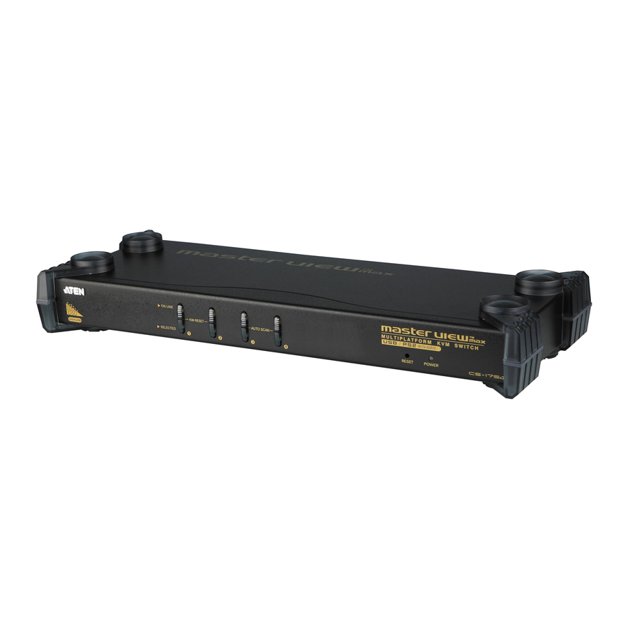
Introduction CS-1754 Front View 1. Port Selection Switches Press a switch to access the computer attached to its corresponding port. Pressing Buttons 1 and 2 simultaneously for 2 seconds performs a keyboard and mouse reset. Pressing Buttons 3 and 4 simultaneously for 2 seconds starts Auto Scan Mode. -
Page 11: Cs-1758 Front View
CS-1758 Front View 1. Port Selection Switches Press a switch to access the computer attached to its corresponding port. Pressing Buttons 1 and 2 simultaneously for 2 seconds performs a keyboard and mouse reset. Pressing Buttons 7 and 8 simultaneously for 2 seconds starts Auto Scan Mode. -
Page 12: Cs-1754 / Cs-1758 Rear View
CS-1754 / CS-1758 Rear View F/W UPGRADE NORMAL RECOVER F/W UPGRADE NORMAL RECOVER CS-1754 / CS-1758 User Manual... - Page 13 1. Firmware Upgrade Section Firmware Upgrade Switch During normal operation and while performing a fimware upgrade, this switch should be in the NORMAL position. See p. 45 for details about the use of this switch. Firmware Upgrade Port The Firmware Upgrade Cable that transfers the firmware upgrade data from the administrator’s computer to the CS-1754 / CS-1758 plugs into this RJ-11 connector.
-
Page 14: Installation
Installation Before you Begin 1. Make sure that power to all the devices you will be connecting up have been turned off. You must unplug the power cords of any computers that have the Keyboard Power On function. Otherwise, the switch will receive power from the computer. - Page 15 Single Stage Installation: F/W UPGRADE NORMAL RECOVER CS-1754 / CS-1758 User Manual...
- Page 16 USB Cable Connection: PS/2 Cable Connection: CS-1754 / CS-1758 User Manual...
-
Page 17: Two Stage Installation
Two Stage Installation To control even more computers, up to four/eight additional Master View CS-1754/CS-1758 units can be cascaded from the CPU ports of the First Stage unit. The cascaded Master Views that connect back to the First Stage unit are considered Second Stage units. As many as 16 (CS-1754) or 64 (CS-1758) computers can be controlled in a complete two stage installation. - Page 18 5. Repeat steps 3 and 4 for any other computers you are connecting up. 6. For each Second Stage unit, plug the power adapter cable into its Power Jack, then plug the power adapter into an AC source. 7. Plug the First Stage unit’s power adapter cable into its Power Jack, then plug the power adapter into an AC source.
-
Page 19: Three Stage Installation
Three Stage Installation The procedures for setting up a three stage installation are essentially the same as for a two stage installation. With a three stage setup, as many as 64 (CS-1754) or 512 (CS-1758) computers can be controlled in a complete installation. - Page 20 Three Stage Installation: F/W UPGRADE NORMAL RECOVER NORMAL RECOVER CS-1754 / CS-1758 User Manual...
-
Page 21: Operation
Operation Hot Plugging The Master View CS-1754 / CS-1758 supports hot plugging. Components can be removed and added back into the installation by unplugging and replugging their cables from their respective ports without the need to shut the switch down. For hot plugging to work properly, the following procedures must be observed: w Hot Plugging CPU Ports: When hot plugging cables from the CPU ports:... -
Page 22: Powering Off And Restarting
Powering Off and Restarting If it becomes necessary to Power Off one of the Master View units, before starting it back up you must do the following: 1. Shut down all the computers that are attached to the unit. If there are Master View stations cascaded down from it, all the cascaded stations and the computers attached to them must be shut down, as well. -
Page 23: Port Id Numbering
Port ID Numbering Each CPU Port on a CS-1754 / CS-1758 installation is assigned a unique Port ID. You can directly access any computer on any level of the installation by specifying the Port ID of the CPU port that the computer is connected to - either with the Hotkey port selection method (see p. -
Page 24: Port Selection
Port Selection The CS-1754 / CS-1758 provides three methods to obtain instant access to any computer in your installation: Manual, Hotkey, and OSD. w Manual Simply press the appropriate Port Selection Switch on the CS-1754 / CS-1758’s front panel. After you press the switch, the Selected LED lights to indicate that the port has the KVM focus. -
Page 25: Hotkey Port Control
Hotkey Port Control The CS-1754 / CS-1758 provides an extensive, easy-to-use, hotkey function that makes it convenient to control and configure your KVM installation from the keyboard. All hotkey operations begin by invoking Hotkey Mode. Note: The hotkey function must be enabled to use hotkey operations. See Hotkey Command Mode, p. -
Page 26: Hotkey Port Access
Hotkey Port Access Hotkey Port Access allows you to select which computer has the KVM focus and/or which computer has access to the USB peripherals. CPU Port selection and USB Port assignment can be done independently (asynchronously). One computer can have the KVM focus while another has access to the USB peripherals. - Page 27 w Auto Scan Mode The CS-1754 / CS-1758’s Auto Scan feature automatically switches among all the active CPU Ports that are accessible to the currently logged on User at regular intervals (see Scan Mode of the OSD F3 SET function, p. 33), so that he can monitor their activity automatically.
-
Page 28: Hotkey Configuration
Hotkey Configuration Alternate Hotkey Invocation Keys: An alternate set of Hotkey Invocation keys is provided in case the default set conflicts with programs running on the computers. To switch to the alternate Hotkey Invocation set, do the following: 1. Invoke HKM (see p. 19) 2. -
Page 29: Platform / Language Setup
Platform / Language Setup: The CS-1754 / CS-1758’s default port settings are for a PC Compatible operating platform, and the US English keyboard language code. You can modify these for each port by bringing the KVM focus to the port you want to change and using the hotkey combinations shown in the table below. -
Page 30: Miscellaneous
Miscellaneous: Hotkeys are also used to reset the USB, and toggle the beeper On and Off. To perform any of these operations, do the following: 1. Invoke HKM (see p. 19) 2. Press and release the appropriate action key (see table). After completing a setting, you automatically exit HKM. -
Page 31: Hotkey Summary Table
Hotkey Summary Table [Num Lock] + [-] [Port ID] [Enter] [F1] [F2] [F3] [F5] [R] [Enter] Note: The brackets indicate the keys you should press. Simply press the indicated keys - do not type the brackets. CS-1754 / CS-1758 User Manual Switches access to the computer that corresponds to that Port ID. -
Page 32: Keyboard Emulation
Keyboard Emulation Sun Keyboard The PC Compatible (101/104 key) keyboard can emulate the functions of the Sun keyboard when the Control key [Ctrl] is used in conjunction with other keys. The corresponding functions are shown in the table below. Note: When using [Ctrl] combinatons, press and release the Ctrl key, then press and release the activation key. -
Page 33: Mac Keyboard
Mac Keyboard The PC Compatible (101/104 key) keyboard can emulate the functions of the Mac keyboard. The emulation mappings are listed in the table below. Note: When using key combinatons, press and release the first key (Ctrl or Alt), then press and release the activation key. PC Keyboard [Shift] [Ctrl]... -
Page 34: Osd Operation
OSD Operation OSD Overview The On Screen Display (OSD) is used to handle all computer control and switching procedures. All procedures start from the OSD Main Menu. To pop up the Main Menu, tap the [Scroll Lock] key twice. Note: You can optionally change the Hotkey to the Ctrl key (see OSD Hotkey, p. -
Page 35: Osd Navigation
OSD Navigation To dismiss the menu, and deactivate OSD, Click the X at the upper right corner of the OSD Window; or press [Esc]. To Logout, Click F8 at the top of the Main Screen, or press [F8]. To move up or down through the list one line at a time, Click the Up and Down Triangle symbols ( Keys. -
Page 36: Osd Functions
OSD Functions OSD functions are used to configure and control the OSD. For example, you can: rapidly switch to any port; scan selected ports only; limit the list you wish to view; designate a port as a Quick View Port; create or edit a port name;... - Page 37 w F2 LIST: The LIST function lets you broaden or narrow the scope of which ports the OSD displays (lists) on the Main Screen. Many of the OSD functions only operate on the computers that have been selected for listing on the Main Screen with this function. The choices and their meanings are given in the table below: Choice Lists all of the ports on the installation.
- Page 38 w F3 SET: This function allows the Administrator and each User to set up their own working environment. A separate profile for each is stored by the OSD and is activated according to the Username that was provided during Login. To change a setting: Double Click it;...
- Page 39 (F3 SET: continued) Setting PORT ID Selects how the Port ID is displayed: the Port Number alone DISPLAY (PORT NUMBER); the Port Name alone (PORT NAME); or the Port MODE Number plus the Port Name (PORT NUMBER + PORT NAME). The default is PORT NUMBER + PORT NAME.
- Page 40 w F4 ADM: F4 is an Administrator only function. It allows the Administrator to configure and control the overall operation of the OSD. To change a setting Double Click it; or use the Up and Down Arrow Keys to move the highlight bar to it then press [Enter].
- Page 41 (F4 ADM: continued) Setting EDIT PORT To help remember which computer is attached to a particular NAMES port, every port can be given a name. This function allows the Administrator to create, modify, or delete port names. Note: Only the Ports currently chosen for the LIST view on the main OSD screen (see p.
- Page 42 (F4 ADM: continued) Setting SET QUICK This function lets the Administrator select which Ports to include as VIEW PORTS Quick View ports. Note: Only the Ports currently chosen for the LIST view on the main OSD screen (see p. 31), show up here. w To select/deselect a port as a Quick View Port, use the Navigation Keys to move the highlight bar to it, then Press [Enter].
- Page 43 w F7 SCAN: The SCAN function allows you to automatically switch among the available computers at regular intervals so that you can monitor their activity without having to take the trouble of switching manually. The selection of computers to be included for Auto Scanning is made with the Scan Mode setting under the F3 SET function (see p.
- Page 44 w F8 LOUT: LOUT (Log out) logs you out of OSD control of the computers, and blanks the Console screen. After using this function you must log in all over again to regain access to the OSD. This is different from simply pressing [Esc] when you are at the Main Screen to deactivate the OSD, where all you have to do to reenter the OSD is tap the OSD Hotkey.
-
Page 45: The Firmware Upgrade Utility
The Firmware Upgrade Utility The Windows-based Firmware Upgrade Utility (FWUpgrade.exe) provides a smooth, automated process for upgrading the KVM switch’s firmware. The Utility comes as part of a Firmware Upgrade Package that is specific for each device. New firmware upgrade packages are posted on our web site as new firmware revisions become available. -
Page 46: Starting The Upgrade
4. Shut down the computers on your CS-1754 / CS-1758 installation. 5. From your KVM switch console, bring up the OSD (see p. 28) and select the F4ADM function. 6. Scroll down to FIRMWARE UPGRADE (see p. 36). Press [Enter], then press [Y] to invoke Firmware Upgrade Mode For your reference, the current firmware upgrade version displays on the screen. - Page 47 3. Click Next to continue. The Firmware Upgrade Utility main screen appears: The Utility inspects your installation. All the devices capable of being upgraded by the package are listed in the Device List panel. 4. As you select a device in the list, its description appears in the Device Description panel.
- Page 48 5. After you have made your device selection(s), Click Next to perform the upgrade. If you enabled Check Firmware Version, the Utility compares the device’s firmware level with that of the upgrade files. If it finds that the device’s version is higher than the upgrade version, it brings up a dialog box informing you of the situation and gives you the option to Continue or Cancel.
-
Page 49: Upgrade Succeeded
Upgrade Succeeded After the upgrade has completed, a screen appears to inform you that the procedure was successful: Click Finish to close the Firmware Upgrade Utility. CS-1754 / CS-1758 User Manual... -
Page 50: Upgrade Failed
Upgrade Failed If the upgrade failed to complete successfully a dialog box appears asking if you want to retry. Click Yes to retry. If you Click No, the Upgrade Failed screen appears: Click Cancel to close the Firmware Upgrade Utility. See the next section, Firmware Upgrade Recovery, for how to proceed. -
Page 51: Firmware Upgrade Recovery
Firmware Upgrade Recovery There are basically two conditions that call for firmware upgrade recovery: When you begin a firmware upgrade, but decide not to proceed with it. When the Mainboard firmware upgrade fails. Note: If one of the cascaded switches fails to upgrade successfully, unplug it from the installation and perform the recovery and upgrade operation independently. -
Page 52: Appendix
Appendix Master View Connection Tables The following tables indicate the relationship between the number of Master View Units and the number of computers that they control: w CS-1758: Computers 1 - 8 8 -15 15 - 22 22 - 29 29 - 36 36 - 43 43 - 50... -
Page 53: Troubleshooting
w CS-1754: Computers 1 - 4 4 - 7 7 - 10 10 - 13 13 - 16 16 - 19 Troubleshooting Symptom Possible Cause Erratic Unit not receiving behavior. enough power. Keyboard Keyboard and/or and/or Mouse mouse need to be not responding. -
Page 54: Specifications
Specifications Function Computer Connections CPU Port Selection LEDs On Line Selected Console Keyboard Connectors Mouse Video Audio KVM data Connectors Audio Firmware Upgrade Power Adapter Scan Interval Resolution Power Consumption Operating Temperature Storage Temperature Humidity Housing Weight Dimensions (L x W x H) CS-1754 Front Panel Switches;... -
Page 55: Limited Warranty
Limited Warranty IN NO EVENT SHALL THE DIRECT VENDOR’S LIABILITY EXCEED THE PRICE PAID FOR THE PRODUCT FROM THE DIRECT, INDIRECT, SPECIAL, INCIDENTAL OR CONSEQUENTIAL DAMAGES RESULTING FROM THE USE OF THE PRODUCT, DISK OR ITS DOCUMENTATION. The direct vendor makes no warranty or representation, expressed, implied, or statutory with respect to the contents or use of this documentation, and specially disclaims its quality, performance, merchantability, or fitness for any particular purpose.