
Related Manuals for BOXLIGHT CD737x


Summary of Contents for BOXLIGHT CD737x
- Page 1 19462 Powder Hill Place Poulsbo, WA 98370 800.762.5757 360.779.7901 www.boxlight.com CD737x...
- Page 2 Copyright This publication, including all photographs, illustrations and software, is protected under international copy- right laws, with all rights reserved. Neither this manual, nor any of the material contained herein, may be reproduced without written consent of the author. © Copyright January, 2006 Disclaimer The information in this document is subject to change without notice.
- Page 3 — — — Important Safety Information Congratulations on purchasing the DLP projector! Important: It is strongly recommended that you read this section carefully before using the projector. These safety and usage instructions will ensure that you enjoy many years safe use of the projector. Keep this manual for future reference.
- Page 4 Remote Control The remote control has a laser for pointing out items on a screen. DANGER: Do not point the laser in the eyes. Doing so can damage the eyes permanently. General Safety Information Do not open the unit case. Aside from the projection lamp, there are no user-serviceable parts in the unit.
-
Page 5: Table Of Contents
— — — Table of contents GETTING STARTED ................................1 ................................1 ACKING HECKLIST ............................... 2 IEWS OF ROJECTOR ARTS Front-left view................................. 2 Top view—OSD buttons and LEDs ..........................3 Rear view—connectors ..............................5 Bottom view..................................7 ..............................8 EMOTE ONTROL ARTS .......................... - Page 6 EN 55022 W ................................. 42 ARNING – v –...
-
Page 8: Getting Started
ETTING TARTED Packing Checklist Carefully unpack the projector and check that the following items are included: DLP P ROJECTOR EMOTE ONTROL AAA B WITH ATTERIES... -
Page 9: Views Of Projector Parts
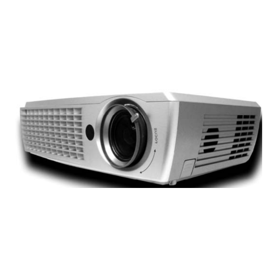
— — — Views of Projector Parts Front-left view ABEL ESCRIPTION EE PAGE Zoom Enlarge the projected image See OSD buttons and LEDs below Projection lamp cover Remove when changing lamp IR receiver Receiver for IR signal from remote control Lens/focus Remove cover, turn the lens to focus Height adjuster... -
Page 10: Top View-Osd Buttons And Leds
— — — Top view—OSD buttons and LEDs READY POWER KEYSTONE POWER SOURCE VOL - VOL + AUTO MENU ABEL ESCRIPTION EE PAGE Volume/ Decrease volume 16, 17 left cursor Navigate and change settings in the OSD Keystone/ Correct image-trapezoid (narrower top) effect 15, 17 Up cursor Navigate and change settings in the OSD... - Page 11 — — — ABEL ESCRIPTION EE PAGE Auto Optimizes image size, position, and resolution Menu Open/exit the On-Screen Display (OSD) Change settings in the OSD Enter Correct image-trapezoid (narrower bottom) effect Keystone/ 15, 17 Navigate and change settings in the OSD Down cursor —...
-
Page 12: Rear View-Connectors
— — — Rear view—connectors ABEL ESCRIPTION EE PAGE DVI-I Connect the DVI cable(supplied) from a computer RGB IN Connect a VGA cable(not supplied) from a computer RGB OUT Connect to a monitor RS-232 Installation control and firmware upgrades Connect the USB cable (supplied) from a computer Audio-in Connect the audio cable (not supplied) from the input de- vice... - Page 13 — — — ABEL ESCRIPTION EE PAGE Kensington Lock Secure to permanent object with a Kensington Lock system Pr/Cr Component Pb/Cb Connect a component video enabled device video in Note: If your video equipment has both S-video, RCA jacks (composite video) or component video or connect to the S-video connector, or component video.
-
Page 14: Bottom View
— — — Bottom view ABEL ESCRIPTION EE PAGE Height adjuster buttons Push to release height adjusters Height adjusters Adjusters drop down when adjuster buttons are pushed Ceiling support holes Contact your dealer for information on mounting the projector on a ceiling. -
Page 15: Remote Control Parts
— — — Remote Control Parts Important: 1. Avoid using the projector with bright fluorescent lighting turned on. Certain high-frequency fluo- rescent lights can disrupt remote control operation. 2. Be sure nothing obstructs the path between the remote control and the projector. If the path be- tween remote and projector is obstructed, you can bounce the remote signal off certain reflective surfaces such as projector screens. - Page 16 — — — ABEL ESCRIPTION EE PAGE Up arrow when connected through USB to a PC Right Right arrow when connected through USB to a PC Down Down arrow when connected through USB to a PC Page Down Page down when connected through USB to a PC Up cursor Right cursor Navigate and change settings in the OSD...
-
Page 17: Remote Control Operating Range
— — — Remote Control Operating Range The remote control uses infrared transmission to control the projector. It is not necessary to point the remote directly at the projector. Provided you are not holding the remote perpendicular to the sides or the rear of the projector, the remote functions within a radius of about (7) meters (23 feet) and 30 de- grees above or below the projector level. -
Page 18: Setup And Operation
ETUP AND PERATION Inserting the Remote Control Batteries Remove the battery compartment cover by sliding the cover in the direction of the arrow. Insert the supplied batteries taking note of the polarity (+/-) as shown here. Replace the cover. Caution: 1. -
Page 19: Connecting Input Devices
— — — Connecting Input Devices A PC or notebook computer as well as video devices can be connected to the projector at the same time. Video devices include DVD, VCD, and VHS players, as well as movie camcorders and digital still cameras. Check the user manual of the connecting device to confirm it has the appropriate output connector. -
Page 20: Starting And Shutting Down The Projector
— — — Starting and Shutting down the Projector Connect the power cord to the projec- tor. Connect the other end to a wall outlet. (A) Turn on the power switch. (B) The Power LED and Lamp-ready LED turn on. Remove the lens cover. -
Page 21: Adjusting The Projector Level
— — — Adjusting the Projector Level Take note of the following when setting up the projector: • The projector table or stand should be level and sturdy. • Position the projector so that it is perpendicular to the screen. •... -
Page 22: Adjust The Zoom, Focus And Keystone
— — — Adjust the Zoom, Focus and Keystone Use the Image-zoom con- trol (on the projector only) to resize the projected im- age and screen size Use the Image-focus con- trol (on the projector only) to sharpen the projected image Use the Keystone buttons (on the projector or the... -
Page 23: Adjusting The Volume
— — — Adjusting the Volume Press the Volume +/- but- tons on the projector or the remote control. The volume control ap- pears on the display. Use the Volume +/- but- tons to adjust the level. Press the Mute button (on the remote control only) to turn off the volume. -
Page 24: On-Screen Display Menu Settings
CREEN ISPLAY ETTINGS On-Screen Display Menu Controls The projector has an On-Screen Display (OSD) that lets you make image adjustments and change various settings. Navigating the OSD You can use the remote control or the buttons on the top of the projector to navigate and make changes to the OSD. -
Page 25: Setting The Osd Language
— — — Setting the OSD Language You may want to reference the OSD on your projector while reading this section. Set the OSD lan- guage to your preference before continuing. (The default language is English.) 1. Press the Menu button. The Main menu appears. 2. -
Page 26: Main Menu
— — — Main Menu Press the Menu button to open the OSD menu. If necessary, press to move to the Main menu. Press to move up and down in the Main menu. Press to change values for settings, and then press Enter to confirm the new setting. - Page 27 — — — Main Menu Items Supported for Each Input Source Depending on the video source not all items in the OSD are available. Items that are available for each input source are marked with “X”. Items that are not available can not be selected in the OSD. Function Component Video Composite Video...
-
Page 28: Setup Menu
— — — Setup Menu Press the Menu button to open the OSD menu. Press to move to the Setup menu. Press move up and down in the Setup menu. Press to change values for settings, and then press En- ter to confirm the new setting. -
Page 29: Advance Feature
— — — Advance Feature Press the Menu button to open the OSD menu. Press to move to the Setup menu. Press move to the Advance Feature, press Enter. Press to move up and down in the Advance Fea- ture. Press to change values for settings, and then press Enter to confirm the new setting. -
Page 30: User Color
— — — User Color Press the Menu button to open the OSD menu. Press to move to the Setup menu. Press move to the Advance Feature, press Enter. Press to move to the User Color, press Enter. Press to move up and down to select a color. Press to change values for settings, and then press Enter to confirm the new setting. - Page 31 — — — Setup Menu Items Supported for Each Input Source Depending on the video source not all items in the OSD are available. Items that are available for each input source are marked with “X”. Items that are not available can not be selected in the OSD. Function Component Video Composite Video...
-
Page 32: Config Menu
— — — Config Menu to move to the Config menu. Press Press the Menu button to open the OSD menu. Press move up and down in the Config menu. Press to change values for settings, and then press En- ter to confirm the new setting. -
Page 33: Utility Menu
— — — Utility Menu Press the Menu button to open the OSD menu. Press to move to the Utility menu. Press move up and down in the Utility menu. Press to change values for settings, and then press En- ter to confirm the new setting. -
Page 34: Language Menu
— — — Language Menu Press the Menu button to open the OSD menu. Press to move to the Language menu. Press to move up and down in the Language menu. ESCRIPTION EFAULT English French German Italian Press the cursor button to move up and down in the menu. -
Page 35: Status Menu
— — — Status Menu Press the Menu button to open the OSD menu. Press to move to the Status menu. Press move up and down in the Status menu. Press to change values for settings, and then press En- ter to confirm the new setting. -
Page 36: Maintenance And Security
AINTENANCE AND ECURITY Replacing the Projection Lamp The projection lamp should be replaced when it burns out. It should only be replaced with a certified replacement part, which you can order from your local dealer. Important: 1. The lamp contains a certain amount of mercury and should be disposed of according to local or- dinance regulations. -
Page 37: Resetting The Lamp
— — — Reverse Steps 1 to 4 to install the new lamp module. Note: The lamp module should be oriented as shown here when replac- ing. Resetting the Lamp After replacing the lamp, reset the lamp hour counter to zero. Refer to the following: Press the Menu button to open the Main menu. -
Page 38: Cleaning The Projector
— — — Cleaning the Projector Cleaning the projector to remove dust and grime will help ensure trouble-free operation. Warning: 1. Be sure to turn off and unplug the projector at least an hour before cleaning. Failure to do so could result in a severe burn. -
Page 39: Cleaning The Case
— — — Cleaning the Case Refer to the following to clean the projector case. 1. Wipe off dust with a clean dampened cloth. 2. Moisten the cloth with warm water and mild detergent (such as used to wash dishes), and wipe the case. -
Page 40: Troubleshooting
ROUBLESHOOTING Common problems and solutions These guidelines provide tips to deal with problems you may encounter while using the projector. If the problem remains unsolved, contact your dealer for assistance. Often after time spent troubleshooting, the problem is traced to something as simple as a loose con- nection. -
Page 41: Led Error Messages
— — — LED Error Messages TATUS NUMBER OF FLASHES ESCRIPTION EMEDY Power Flashing Lamp not ready Do not press the power button. System overheated Allow the projector to cool down. System interface error Contact your dealer for assistance. Lamp error Replace the lamp module. -
Page 42: Lamp Problems
— — — 1. Set the Frequency and Tracking settings on the Utility menu of the OSD to the default settings. 2. To ensure the problem is not caused by a connected PC’s video card, connect to another computer. Problem: The image is flat with no contrast 1. -
Page 43: Having The Projector Serviced
— — — Having the Projector Serviced If you are unable to solve the problem, you should have the projector serviced. Pack the projector in the original carton. Include a description of the problem and a checklist of the steps you took when trying to fix the problem. -
Page 44: Specifications
PECIFICATIONS Specifications Resolution XGA 1024 x 768 native Bandwidth Up to SXGA 1280 x 1024 @ 60 Hz Power consumption 320 watts(Max.) Lamp 200W (ECO mode 180W) Color 16.7 Million (24-bits/pixel) Weight 3.6 kg (7.9 lbs) Projection distance 1.5 to 10 meter (Max.) Projection screen size 37 inches to 300 inches (Max.) Projection lens... -
Page 45: Input/Output Connectors
— — — Input/output connectors DVI-I RGB in RGB out Video Composite video (RCAx1) S-Video (Mini-DIN) Component video Y,Pb/Cb,Pr/Cr (RCAx3) Audio Mini-jack in Mini-jack out Right and left in (RCAx2) Service/upgrades RS-232 Security Kensington slot — 38 —... -
Page 46: Projection Distance Versus Projection Size
— — — Projection Distance versus Projection Size L Projection Distance Max. Screen Size Min. Screen Size Projection Distance Diagonal Width Height Diagonal Width Height 1.5m 1.14m 0.91m 0.68m 0.94m 0.75m 0.56m 4.92' 45" 36" 27" 36.88" 29.5" 22.1" 1.52m 1.22m 0.91m 1.25m... -
Page 47: Timing Mode Table
— — — Timing Mode Table The native resolution is 800 x 600 for the SVGA series and 1024 x 768 for the XGA series. Resolu- tion other than native mode may display with uneven size of text or lines. The following table shows the supported timing modes. -
Page 48: Dimensions
— — — Dimensions 32.8 cm (12.9 inches) – 41 –... -
Page 49: Regulatory Compliance
EGULATORY OMPLIANCE FCC Warning This equipment has been tested and found to comply with the limits for a Class B digital device pursuant to Part 15 of the FCC Rules. These limits are designed to provide reasonable protection against harmful interference when the equipment is operated in a commercial environment.
Need help?
Do you have a question about the CD737x and is the answer not in the manual?
Questions and answers