Table of Contents
Advertisement
Quick Links
DVD-S663/DV-S6165
This manual has been provided for the use of authorized YAMAHA Retailers and their service personnel.
It has been assumed that basic service procedures inherent to the industry, and more specifically YAMAHA Products, are already
known and understood by the users, and have therefore not been restated.
WARNING:
IMPORTANT:
The data provided is believed to be accurate and applicable to the unit(s) indicated on the cover. The research, engineering, and
service departments of YAMAHA are continually striving to improve YAMAHA products. Modifications are, therefore, inevitable
and specifications are subject to change without notice or obligation to retrofit. Should any discrepancy appear to exist, please
contact the distributor's Service Division.
WARNING:
IMPORTANT:
I CONTENTS
TO SERVICE PERSONNEL ...................................... 2-3
REGION MANAGEMENT INFORMATION .................... 4
FRONT PANELS ............................................................ 5
REAR PANELS .......................................................... 5-7
REMOTE CONTROL PANEL ........................................ 7
INTERNAL VIEW ......................................................... 10
1 0 1 1 0 2
Failure to follow appropriate service and safety procedures when servicing this product may result in personal
injury, destruction of expensive components, and failure of the product to perform as specified. For these reasons,
we advise all YAMAHA product owners that any service required should be performed by an authorized
YAMAHA Retailer or the appointed service representative.
The presentation or sale of this manual to any individual or firm does not constitute authorization, certification or
recognition of any applicable technical capabilities, or establish a principle-agent relationship of any form.
Static discharges can destroy expensive components. Discharge any static electricity your body may have
accumulated by grounding yourself to the ground buss in the unit (heavy gauge black wires connect to this buss).
Turn the unit OFF during disassembly and part replacement. Recheck all work before you apply power to the unit.
.................................... 8-9
.............................. 10
........................... 11-12
Copyright © 2008
This manual is copyrighted by YAMAHA and may not be copied or
redistributed either in print or electronically without permission.
DVD PLAYER
SERVICE MANUAL
SERVICE MANUAL
SERVICE MANUAL
IMPORTANT NOTICE
DISASSEMBLY PROCEDURES ................................. 13
........................................................................ 14
BLOCK DIAGRAM ....................................................... 16
WIRING DIAGRAM ...................................................... 17
PRINTED CIRCUIT BOARDS ................................ 18-25
SCHEMATIC DIAGRAMS ...................................... 26-33
REPLACEMENT PARTS LIST .............................. 34-35
REMOTE CONTROL .................................................... 36
All rights reserved.
15
P.O.Box 1, Hamamatsu, Japan
'08.07
Advertisement
Table of Contents

Related Manuals for Yamaha DVD-S663


Summary of Contents for Yamaha DVD-S663
-
Page 1: Table Of Contents
This manual has been provided for the use of authorized YAMAHA Retailers and their service personnel. It has been assumed that basic service procedures inherent to the industry, and more specifically YAMAHA Products, are already known and understood by the users, and have therefore not been restated. -
Page 2: To Service Personnel
DVD-S663/DV-S6165 I TO SERVICE PERSONNEL AC LEAKAGE TESTER OR 1. Critical Components Information WALL EQUIPMENT EQUIVALENT OUTLET UNDER TEST Components having special characteristics are marked Z and must be replaced with parts having specifications equal to those originally installed. 2. Leakage Current Measurement (For 120V Models Only) - Page 3 DVD-S663/DV-S6165 Laser Diode Properties Type: Semiconductor laser GaAs/GaAlAs Wave length: 650 nm (DVD) 780 nm (VCD/CD) Output Power: 7 mW (DVD) 10 mW (VCD/CD) Beam divergence: 60 degree WARNING The use of optical instruments with this product will increase eye hazard.
-
Page 4: Prevention Of Electrostatic Discharge
DVD-S663/DV-S6165 I PREVENTION OF ELECTROSTATIC DISCHARGE The laser diode in the DVD mechanism may be damaged due to static electricity from clothes or the human body. Use caution to prevent electrostatic damage when servicing or handling the DVD-mechanism. 1. Grounding for electrostatic damage prevention Some devices, such as the DVD player, use an optical pickup (laser diode) that will be damaged by static electricity in the working environment. -
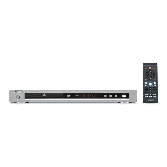
Page 5: Front Panels
DVD-S663/DV-S6165 I FRONT PANELS DVD-S663 (U, K, A, G, F, L, P, J models) DV-S6165 (U model) I REAR PANELS DVD-S663 (U model) DVD-S663 (K model) - Page 6 DVD-S663/DV-S6165 DVD-S663 (A model) DVD-S663 (G model) DVD-S663 (F model) DVD-S663 (L model) DVD-S663 (P model) DVD-S663 (J model)
-
Page 7: Remote Control Panel
DVD-S663/DV-S6165 DV-S6165 (U model) I REMOTE CONTROL PANEL DVD-16... -
Page 8: Specifications
DVD-S663/DV-S6165 I SPECIFICATIONS PLAYBACK SYSTEM / CONNECTIONS / DVD Video Video output RCA/Phono x 1 (yellow) DVD-R, DVD-RW, DVD-R DL S-video output Mini DIN, 4 pins x 1 DVD+R, DVD+RW, DVD+R DL Component video output Video CD, SVCD (U, K, A, G, F, L, P models) - Page 9 DVD-S663/DV-S6165 • DIMENSIONS / Manufactured under license from Dolby Laborato- ries. Dolby and the double-D symbol are trademarks of Dolby Laboratories. DTS and DTS Digital Out are registered trademarks and the DTS logos and Symbol are trademarks of DTS, Inc.
-
Page 10: Internal View
DVD-S663/DV-S6165 I INTERNAL VIEW D2 P.C.B. (J model) AV P.C.B. 3 MPEG P.C.B. FRONT (3) P.C.B. Power Supply Unit Loader Ass'y FRONT (2) P.C.B. FRONT (1) P.C.B. USB Connector I REPAIR NOTES / None of the components of the following units can be supplied separately. -
Page 11: Trade Mode
DVD-S663/DV-S6165 I TRADE MODE / This unit provides TRADE mode which prevents the disc tray from opening even when the “OPEN/CLOSE” key is pressed. • Activating TRADE mode The power to this unit should be turned on before activating the TRADE mode. -
Page 12: Trade Mode
DVD-S663/DV-S6165 • Canceling TRADE mode The power to this unit should be turned on before canceling TRADE mode. 1. Press and hold the “STOP” key on the remote control. (Fig. 4) The disc tray opens after about 2 second. 2. Press the “2”, “5” and “9” keys on the remote con- trol in that order. -
Page 13: Disassembly Procedures
DVD-S663/DV-S6165 I DISASSEMBLY PROCEDURES When disassembling, use the special screw driver with tip shape in figure. See REPLACEMENT PARTS LIST for item numbers. Mounting Top Cover [240] 2.7 mm Remove 5 screws [267] (2 on side and 3 on rear side). - Page 14 DVD-S663/DV-S6165...
-
Page 15: Test Mode
DVD-S663/DV-S6165 I TEST MODE / • Starting Test Mode • Panel Key Test a. Connect the power cable to the AC power outlet. The display changes as shown below by pressing the b. Press the “STANDBY/ON” key while simulta- specified key. -
Page 16: Block Diagram
DVD-S663/DV-S6165 I BLOCK DIAGRAM LD_DVD LD_CD 1303 1100 1103 1301 7300 +5V_STBY 7102 VR_DVD connector 1104 Opto- 1200 VR_CD 1 +5V_STBY Coupler Ext_IR 2 GND Front (1) Display 7100 10 E 3 EXT_IR FRONT (2) 1 Stby_ON Trans 1302 Ext_IR... -
Page 17: Wiring Diagram
DVD-S663/DV-S6165 I WIRING DIAGRAM HLEM10S-1R 1109 1100 1202 1100 HLEM10S-1R AC IN (J model) 1209 Power Supply Unit 1201 1212 1200 to USB connector (Front panel) 8P/340/8P 319804002080 319804002080 1104 1200 319804000020 319804000020 FRONT (2) Standby/ON Loader Ass'y FRONT (1) Display... -
Page 18: Printed Circuit Boards
DVD-S663/DV-S6165 The first digit of a component indicates the component type. I PRINTED CIRCUIT BOARDS 1xxx : Connector 3xxx : Resistor 5xxx : Coil 7xxx : IC, Transistor, FET FOR INFORMATION ONLY (COMPONENT PARTS NOT AVAILABLE) 2xxx : Capacitor 4xxx : SMD jumper... - Page 19 DVD-S663/DV-S6165 The first digit of a component indicates the component type. 1xxx : Connector 3xxx : Resistor 5xxx : Coil 7xxx : IC, Transistor, FET 2xxx : Capacitor 4xxx : SMD jumper 6xxx : Diode 9xxx : Wire jumper MPEG...
- Page 20 DVD-S663/DV-S6165 The first digit of a component indicates the component type. 1xxx : Connector 3xxx : Resistor 5xxx : Coil 7xxx : IC, Transistor, FET 2xxx : Capacitor 4xxx : SMD jumper 6xxx : Diode 9xxx : Wire jumper (Top view)
- Page 21 DVD-S663/DV-S6165 The first digit of a component indicates the component type. 1xxx : Connector 3xxx : Resistor 5xxx : Coil 7xxx : IC, Transistor, FET 2xxx : Capacitor 4xxx : SMD jumper 6xxx : Diode 9xxx : Wire jumper (Bottom view)
- Page 22 DVD-S663/DV-S6165 The first digit of a component indicates the component type. 1xxx : Connector 3xxx : Resistor 5xxx : Coil 7xxx : IC, Transistor, FET 2xxx : Capacitor 4xxx : SMD jumper 6xxx : Diode 9xxx : Wire jumper FRONT (1)
- Page 23 DVD-S663/DV-S6165 The first digit of a component indicates the component type. 1xxx : Connector 3xxx : Resistor 5xxx : Coil 7xxx : IC, Transistor, FET 2xxx : Capacitor 4xxx : SMD jumper 6xxx : Diode 9xxx : Wire jumper FRONT (2)
- Page 24 DVD-S663/DV-S6165 The first digit of a component indicates the component type. 1xxx : Connector 3xxx : Resistor 5xxx : Coil 7xxx : IC, Transistor, FET 2xxx : Capacitor 4xxx : SMD jumper 6xxx : Diode 9xxx : Wire jumper (Top view)
- Page 25 DVD-S663/DV-S6165 POWER SUPPLY UNIT (Top view) FRONT (1) (1101) (1200) AC IN POWER SUPPLY UNIT (Bottom view)
-
Page 26: Schematic Diagrams
DVD-S663/DV-S6165 The first digit of a component indicates the component type. I SCHEMATIC DIAGRAMS 1xxx : Connector 3xxx : Resistor 5xxx : Coil 7xxx : IC, Transistor, FET FOR INFORMATION ONLY (COMPONENT PARTS NOT AVAILABLE) 2xxx : Capacitor 4xxx : SMD jumper... - Page 27 DVD-S663/DV-S6165 The first digit of a component indicates the component type. 1xxx : Connector 3xxx : Resistor 5xxx : Coil 7xxx : IC, Transistor, FET 2xxx : Capacitor 4xxx : SMD jumper 6xxx : Diode 9xxx : Wire jumper MPEG 2/2...
- Page 28 DVD-S663/DV-S6165 The first digit of a component indicates the component type. 1xxx : Connector 3xxx : Resistor 5xxx : Coil 7xxx : IC, Transistor, FET 2xxx : Capacitor 4xxx : SMD jumper 6xxx : Diode 9xxx : Wire jumper 1100 C2...
- Page 29 DVD-S663/DV-S6165 The first digit of a component indicates the component type. 1xxx : Connector 3xxx : Resistor 5xxx : Coil 7xxx : IC, Transistor, FET 2xxx : Capacitor 4xxx : SMD jumper 6xxx : Diode 9xxx : Wire jumper AV 2/2...
- Page 30 DVD-S663/DV-S6165 The first digit of a component indicates the component type. 1xxx : Connector 3xxx : Resistor 5xxx : Coil 7xxx : IC, Transistor, FET 2xxx : Capacitor 4xxx : SMD jumper 6xxx : Diode 9xxx : Wire jumper 1100 A6...
- Page 31 DVD-S663/DV-S6165 The first digit of a component indicates the component type. 1xxx : Connector 3xxx : Resistor 5xxx : Coil 7xxx : IC, Transistor, FET 2xxx : Capacitor 4xxx : SMD jumper 6xxx : Diode 9xxx : Wire jumper FRONT 2/2...
- Page 32 DVD-S663/DV-S6165 The first digit of a component indicates the component type. 1xxx : Connector 3xxx : Resistor 5xxx : Coil 7xxx : IC, Transistor, FET 2xxx : Capacitor 4xxx : SMD jumper 6xxx : Diode 9xxx : Wire jumper D2 (J model)
- Page 33 DVD-S663/DV-S6165 POWER SUPPLY UNIT Page 29 to AV_1200 Page 30 to FRONT (1)_1101 POWER TRANSFORMER AC IN...
-
Page 34: Replacement Parts List
DVD-S663/DV-S6165 I REPLACEMENT PARTS LIST • OVERALL ASS’Y When disassembling, use the special screw driver with such tip shape as shown in figure. 2.7 mm J model 8103 J model 3 x 8 P-Tight Black 1002 U, K, A, L,... - Page 35 DVD-S663/DV-S6165 WARNING Components having special characteristics are marked Z and must be replaced with parts having specifications equal to those originally installed. ✻ New Parts...
-
Page 36: Remote Control
DVD-S663/DV-S6165 I REMOTE CONTROL • PANEL • KEY NO. LAYOUT • KEY CODE DVD-16 Key label Code STANDBY (POWER) 7C-80 TOP MENU/RETURN 7C-B1 ON SCREEN 7C-A6 (UP) 7C-B4 H H H H H (LEFT) 7C-B5 Q Q Q Q Q... - Page 37 DVD-S663/DV-S6165...
Need help?
Do you have a question about the DVD-S663 and is the answer not in the manual?
Questions and answers