Table of Contents
Advertisement
Advertisement
Table of Contents

Related Manuals for Exmark PIONEER S SERIES


Summary of Contents for Exmark PIONEER S SERIES
- Page 1 PIONEER S-SERIES ® For Serial Nos. 315,000,000 & Higher Part No. 4502-317 Rev. A...
- Page 2 SAE testing and gross/net power rating standards (J1940, J1995, J1349). Exmark reserves the right to make changes or add improvements to its products at any time without incurring any obligation to make such changes to products manufactured previously.
-
Page 3: Introduction
All Exmark parts are thoroughly tested and inspected before leaving the factory, however, attention is required on your part if you are to obtain the fullest measure of satisfaction and performance. -
Page 4: Table Of Contents
Contents Adjusting the Seat Ride Suspension....43 Electric Clutch Adjustment......43 Cleaning ............45 Introduction ............3 Clean Engine and Exhaust System Safety ..............5 Area ............45 Safety Alert Symbol ......... 5 Remove Engine Shrouds and Clean Safe Operating Practices ........5 Cooling Fins..........45 Safety and Instructional Decals ......11 Clean Hydro Fan Cooling Fins ......45 Specifications ............16... -
Page 5: Safety
Institute in effect at the time of production. explain this material to them; other languages may be available on our website. Exmark designed and tested this lawn mower to offer reasonably safe service; however, failure to comply • Become familiar with the safe operation of the with the following instructions may result in personal equipment, operator controls, and safety signs. - Page 6 Safety • Inspect the area where the equipment is to be DANGER used and remove all rocks, toys, sticks, wires, In certain conditions during fueling, static bones, and other foreign objects which can be electricity can be released causing a spark thrown by the machine and may cause personal which can ignite gasoline vapors.
- Page 7 Safety Operation damage and make repairs before restarting and operating the mower). WARNING – Before clearing blockages. Operating engine parts, especially the muffler, – Whenever you leave the mower. become extremely hot. Severe burns can occur • Stop engine, wait for all moving parts to stop, and on contact and debris, such as leaves, grass, engage parking brake: brush, etc.
- Page 8 Safety • Be aware that operating on wet grass, across steep DANGER slopes or downhill may cause the mower to lose Operating on wet grass or steep slopes can cause traction. Loss of traction to the drive wheels may sliding and loss of control. Wheels dropping over result in sliding and a loss of braking and steering.
-
Page 9: Maintenance And Storage
Charging or jump starting the battery may • Any accessories, alterations, or attachments added produce explosive gases. Battery gases can to the ROPS must be approved by Exmark. explode causing serious injury. • Keep sparks, flames, or cigarettes away Maintenance and Storage from battery. - Page 10 Unauthorized modifications to the original equipment or failure to use original Exmark parts could lead to serious injury or death. Unauthorized changes to the machine, engine, fuel or venting system, may violate applicable...
-
Page 11: Safety And Instructional Decals
Exmark equipment dealer or labels. distributor or from Exmark Mfg. Co. Inc. • Replace all worn, damaged, or missing safety • Safety signs may be affixed by peeling off the signs. - Page 12 Safety 109-6035 116-1496 Side Discharge Units Only 126-4363 1. Cutting/dismemberment hazard, fan and entanglement hazard, belt—Stop engine and remove key before adjusting, servicing or cleaning. 109-6036 1. Read the Operator’s manual 2. Remove the ignition key and read the instructions before servicing or performing maintenance.
- Page 13 Safety 116-4858 117-3848 1. Thrown object hazard—keep bystanders a safe distance from the machine 2. Thrown object hazard, mower-do not operate without the deflector, discharge cover or grass collection system in place. 3. Cutting/dismemberment of hand or foot—stay away from moving parts; keep all guards and shields in place. 116-8283 1.
- Page 14 Safety PTO Switch Symbols 1. PTO–disengage 2. PTO–engage 126-4383 1. Read the Operator’s 3. Unlock manual. 2. Lock 109-6016 1. Read the instructions before servicing or performing 4. Refer to the Operator's manual for grease instructions maintenance 2. Time interval 5.
- Page 15 Safety 116-8668 1. Park brake - Pull rearward to engage. 7. Warning-Read the Operator’s Manual. Do Not operate this machine unless you are trained. Wear hearing protection. 2. Machine speed 8. Warning-Stay away from moving parts; keep all guards in place. Stop engine and remove key before adjusting, servicing, or cleaning.
-
Page 16: Specifications
• Recommended Minimum Battery CCA: 260 CCA • Engine Specifications: See your Engine Owner’s • Battery Voltage: 12 Volt Manual • Polarity: Negative Ground • Engine Oil Type: Exmark 4–Cycle Premium Engine Oil • Fuses: • RPM: Full Speed: 3700 ±50 RPM (PTO not All units: engaged) Idle: 1500 ±100 RPM... -
Page 17: Hydrostatic Ground Drive System
• Cutting Width: Hydro Gear ZT3400 – 48 inch Deck: (121.9 cm) • Hydraulic Oil Type: Exmark Premium Hydro Oil. – 52 inch Deck: (132.1 cm) • Hydraulic Oil Capacity: 77 oz (2.3 L) per side – 60 inch Deck: (152.4 cm) -
Page 18: Dimensions
Specifications Dimensions • Discharge: – Side Discharge: Non “R” models Overall Width: – Rear Discharge: “R” models Side Discharge Units: • Blade Size: – 48 inch Deck: 16.25 inches (41.3 cm) – (3 ea.) 48 inch 52 inch 60 inch Deck Deck Deck... -
Page 19: Torque Requirements
Specifications Torque Requirements Tread Width: (Center to Center of Tires, Widthwise) Bolt Location Torque Side Discharge Units: Blade Drive Sheave 130-160 ft-lb (176-217 N-m) Mounting Nut 48 inch 52 inch 60 inch Blade Mounting 50-60 ft-lb (68-81 N-m) Deck Deck Deck Bolt (lubricate with Drive... -
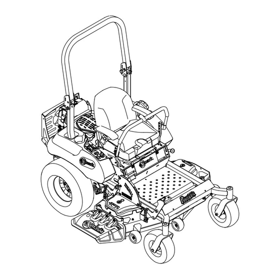
Page 20: Product Overview
Operation Product Overview Operation Note: Determine the left and right sides of the machine from the normal operating position. Controls Motion Control Levers The motion control levers located on each side of the console control the forward and reverse motion of the machine. -
Page 21: Throttle Control
Operation position. Do Not run a warm engine with choke in The ignition switch is used to start and stop the the “ON” position. engine. The switch has three positions “OFF”, “ON” and “START”. Insert key into switch and rotate clockwise to the “ON”... - Page 22 Operation The fuel shut-off valve is used to shut off the fuel when the machine will not be used for a few days, during transport to and from the jobsite, and when parked inside a building. Align valve handle with the fuel line to open. Rotate 90°...
-
Page 23: Pre-Start
Operation PTO Engagement Switch in fuel leakage or damage to the engine or emission system. Located on right console (see Figure 6). Make sure you understand the controls, their Switch must be pulled out (up) to engage the blades. locations, their functions, and their safety Switch is pushed in to disengage the blades. -
Page 24: Starting The Engine
Operation Starting the Engine 1. Move the motion control levers out to the neutral lock position. 2. Pull up and back on the parking brake lever to engage the parking brake. 3. Push down on the PTO switch to the “disengage” position. -
Page 25: Stopping The Engine
Operation Important: To begin movement (forward or The PTO push-pull switch engages the cutting blades. Be sure that all persons are clear of the mower deck backward) the operator must be in the seat, the and discharge area before engaging PTO. brake lever must be disengaged (pushed down) before the motion control levers can be moved in Important: Operator must be in seat before the... -
Page 26: Adjusting The Cutting Height
Operation To turn right, release pressure on the RH motion control lever and the rear of the machine will move towards the rear and to the right. To turn left, release pressure on the LH motion control lever and the rear of the machine will move towards the rear and to the left. - Page 27 Operation Adjusting the Anti-Scalp Rollers It is recommended to change the anti-scalp roller position, when the height of cut has changed. 1. Stop the machine and move the motion control levers outward to the neutral locked position. 2. Disengage the PTO. 3.
-
Page 28: Transporting
Operation (64 mm) and in the center holes when operating in Knowing this information could help you, your height of cuts lower than 2 1/2 inches (64 mm). family, pets, or bystanders avoid injury. Note: When bumpers become worn, switch the To transport the machine: bumpers to the opposite sides of the mower, flipping •... - Page 29 Operation WARNING Loading a machine onto a trailer or truck increases the possibility of tip-over and could cause serious injury or death. • Use extreme caution when operating a machine on a ramp. • Ensure that the ROPS is in the up position and use the seat belt when loading or unloading the machine.
-
Page 30: Maintenance
Maintenance Maintenance Note: Determine the left and right sides of the machine from the normal operating position. WARNING WARNING While maintenance or adjustments are being The engine can become very hot. Touching a hot made, someone could start the engine. engine can cause severe burns. -
Page 31: Periodic Maintenance
100% 16 volts/7 oil fill cap, remove cap and fill to the “FULL” greater Charging amps mark on the dipstick. Exmark 4-Cycle Premium Required Engine Oil is recommended; refer to the Engine 12.4 – 12.6 75–100% 30 Minutes 16 volts/7 Owner's manual for an acceptable alternative. -
Page 32: Check Mower Blades
Maintenance DANGER Jump starting a weak battery that is cracked, frozen, has low electrolyte level, or an open/shorted battery cell, can cause an explosion resulting in serious personal injury. Do Not jump start a weak battery if these conditions exist. 2. -
Page 33: Check Safety Interlock System
Check Safety Interlock Note: If machine does not pass any of these tests, System do not operate. Contact your authorized EXMARK SERVICE DEALER. Service Interval: Before each use or daily Important: It is essential that operator safety... -
Page 34: Check Rollover Protections Systems (Roll Bar) Knobs
Before reinstalling new filter, apply a thin coating 1. Stop engine, wait for all moving parts to stop, and of Exmark 4–Cycle Premium Engine oil on the remove key. Engage parking brake. surface of the rubber seal. Turn filter clockwise 2. -
Page 35: Check Hydraulic Oil Level
NGLI grade #2 multi-purpose gun grease. hydraulic oil. Refer to the following chart for fitting locations 3. Check expansion tank and if necessary add and lubrication schedule. Exmark Premium Hydro Oil to the FULL COLD line (see Figure 26). Lubrication Chart Fitting Initial... -
Page 36: Check Spark Plugs
Important: To prevent seal and bearing damage, Important: Before reinstalling new filters, check the bearing adjustment often. Spin the apply a thin coat of Exmark Premium Hydro caster tire. The tire should not spin freely Oil on the surface of the filters rubber seal. -
Page 37: Check Spark Arrester (If Equipped)
Engine must be running and drive wheels out of vent reinstall plug. must be turning so adjustments can be Exmark Premium Hydro Oil is recommended. performed. Contact with moving parts or hot Refer to the chart for an acceptable alternative: surfaces may cause personal injury. -
Page 38: Thread Locking Adhesives
Maintenance Adjustments 3. If any breaks in the screen or welds are observed, replace arrester. Note: Disengage PTO, shut off engine, wait for 4. If plugging of the screen is observed, remove all moving parts to stop, engage parking brake, and arrester and shake loose particles out of the remove key before servicing, cleaning, or making any arrester and clean screen with a wire brush (soak... -
Page 39: Adjusting The Blade Slope
Maintenance 8. For Rear Discharge Units Only: sitting securely on all four blocks. Make sure that the slack is removed from the deck hangers and A. Raise the deck to the transport (5 inch (12.7 the deck lift foot lever is pushed back against the cm) cutting height) position. -
Page 40: Pump Drive Belt Tension
Maintenance the engine, remove the key, and wait for all moving parts to stop before leaving the operating position. 4. Check the air pressure of all four tires. If needed, adjust to the recommended inflation; refer to Checking the Tire Pressure in Drive System Maintenance section. -
Page 41: Motion Control Handle Adjustment
Maintenance 4. Setup the machine to be pushed by hand (see 8. Reinstall the clevis pin and hair pin and tighten Drive Wheel Release Valves in the Operation down the jam nut. Repeat step 6 and readjust if section). necessary. 5. -
Page 42: Full Forward Tracking Adjustment
Maintenance 2. Loosen the lower bolt just enough to pivot the WARNING control lever fore or aft Figure 34. Tighten both Engine must be running and drive wheels must bolts to secure the control in the new position. be turning so adjustments can be performed. 3. -
Page 43: Adjusting The Seat Ride Suspension
Maintenance Figure 37 1. Bolt 3. Nut Figure 36 2. Spring 4. Additional mounting holes 1. Nut 4. Control plate 2. Turnbuckle 5. Return to neutral plate Up to five springs can be secured to the seat box with 3. Stationary plate 6. - Page 44 Maintenance the machine to cool completely before starting as shown. (Due to the way the rotor and these instructions. armature faces wear (peaks and valleys) it is sometimes difficult to measure the true gap.) 2. Using a pneumatic line, blow out any debris from under the brake pole and around the brake spacers.
-
Page 45: Cleaning
Maintenance Cleaning 1. Stop engine, wait for all moving parts to stop, and remove key. Engage parking brake. 2. Slide seat all the way forward. Clean Engine and Exhaust 3. Remove accumulated debris from the hydro fan System Area cooling fins and upper surfaces. Service Interval: Before each use or daily Clean Debris From Machine (May be required more... -
Page 46: Battery Disposal
Maintenance recycling center or according to your state and local regulations. Battery Disposal DANGER Battery electrolyte contains sulfuric acid, which is poisonous and can cause severe burns. Swallowing electrolyte can be fatal or if it touches skin can cause severe burns. •... -
Page 47: Troubleshooting
Troubleshooting Troubleshooting Important: It is essential that all operator safety mechanisms be connected and in proper operating condition prior to mower use. When a problem occurs, do not overlook the simple causes. For example: starting problems could be caused by an empty fuel tank. The following table lists some of the common causes of trouble. - Page 48 Troubleshooting Problem Possible Cause Corrective Action Engine loses power 1. Engine load is excessive 1. Reduce the ground speed. 2. Air cleaner is dirty. 2. Clean or replace the air cleaner element. 3. Oil level in the crankcase is low. 3.
-
Page 49: Schematics
Schematics Schematics Electrical Diagram... - Page 50 Schematics Electrical Logic Schematic...
- Page 51 Exmark Service Dealer before obtaining any warranty service. conditions herein, that we will repair, replace or adjust any part on these Contact any Exmark Service Dealer to arrange service at their dealership. products and found by us (in the exercise of our reasonable discretion) to To locate a dealer convenient to you, access our website at be defective in factory materials or workmanship.
- Page 52 Notes:...
-
Page 53: Service Record
Service Record Date: Description of Work Done: Service Done By:... - Page 55 G011841 Figure 42 This page may be copied for personal use. 1. The maximum slope you can safely operate the machine on is 15 degrees. Use the slope indicator to determine the degree of slope of hills before operating. Do Not operate this machine on a slope greater than 15 degrees. Fold along the appropriate line to match the recommended slope.
- Page 56 Pack) or Fill in Below Engine Model No. and Spec. No. Model No. Engine Serial No. (E/No) Serial No. ©2014 Exmark Mfg. Co., Inc. Part No. 4502-317 Rev. A Industrial Park Box 808 (402) 223-6285 Beatrice, NE 68310 Fax (402) 223-5489...
Need help?
Do you have a question about the PIONEER S SERIES and is the answer not in the manual?
Questions and answers
Yes what the order number for a hydro pump belt