Valor Portrait 569 Ledge Front Installation Instructions Manual
Hide thumbs
Also See for Portrait 569 Ledge Front:
- Installation instructions manual (21 pages) ,
- Installation manual (23 pages)
Table of Contents
Advertisement
Available languages
Available languages
Quick Links
CSA approved for use with Valor Models 530I Heaters ONLY
Notes: This kit must be installed or serviced
by a qualified installer, service agency or gas
supplier. These instructions are to be used
in conjunction with the main installation
instructions for the above listed heater
models.
The installation of this kit affects the
framing and method of installing the 530
heater.
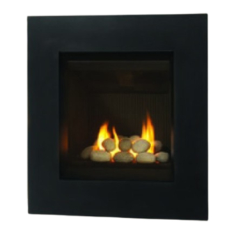
Window frame cover
Trim panel—patina, brushed nickel or black
Overview
(530 engine and 570FPB Finishing Plate sold separately)
4002418-03
© Copyright Miles Industries Ltd., 2010.
P
ortrait
569 Ledge Front
INSTALLATION INSTRUCTIONS
Stand-off
Stud bracket
Cement board
Convection baffle
570FPB Finishing Plate
Trim panel
lead-in
assembly
Installation Sequence
1. Frame the cavity.
2. Install the heater with stud brackets, stand-offs,
insulation, wall switch kit, and cement board.
3. Gas fit and vent heater.
4. Drywall only (no tile, etc.).
5. Assemble and install the mounting frame.
6. Install finishing material (tile, etc.). Finish around or
under 570 Finishing Plate if using it.
7. Assemble and install the trim panel.
Touch control
wall switch
Insulation
Stand-off
Roof
grille
Stud bracket
panel
Mounting frame
530 engine
Advertisement
Table of Contents

Related Manuals for Valor Portrait 569 Ledge Front


Summary of Contents for Valor Portrait 569 Ledge Front
-
Page 1: Installation Instructions
569 Ledge Front INSTALLATION INSTRUCTIONS CSA approved for use with Valor Models 530I Heaters ONLY Installation Sequence Notes: This kit must be installed or serviced 1. Frame the cavity. by a qualified installer, service agency or gas 2. Install the heater with stud brackets, stand-offs, supplier. -
Page 2: Dimensions And Clearances
Dimensions & Clearances Cement board 570 Finishing Plate sold separately center of vent Min. 36” (0.9 m) to combustible materials 1/2” (13 mm) min. under bottom of trim for air gap bottom of trim 3-5/16” (84 mm) 11/16” (17 mm) between bottom of engine and bottom of trim bottom of 570... - Page 3 Framing Wall Finish 30-1/4” (768 mm) to header 3-5/8” (92 mm) cement board supplied 27-3/8” (695 mm) to cement board This is the framing width. Drywall to 23-3/4” (603 mm) wide. Minimum 12-3/4” (324 mm) (Allow extra for rear vent elbow) Wall Finish with 570 finishing plate WALL...
-
Page 4: Installation
Installation LOGS & ROCKS VERSIONS ONLY. Grille cannot be used with coal fuelbed version. Install the grille tab at panel inside the appliance: the top a. Insert the grille in the firebox by aligning one of its side edge to the edge of the firebox as indicated. - Page 5 c. Pull out the receiver box. Remove the batteries Wall Switch from the receiver box if it contains any. You Harness can remove the ignition wire to improve access Ignition Wire to the receiver. CAUTION DO NOT USE a screwdriver or other metallic object to Antenna remove the batteries from the receiver or the handset! This could cause a short circuit to the receiver.
- Page 6 10. Assemble the mounting c. Slide the internal baffle over the screw tips on frame following the the frame’s left piece, under the top piece. Hold steps indicated below. the baffle in place with one hand. Front Fixing points Internal baffle orientation— right side view Screw tip d.
- Page 7 12. Apply wall finish on top of drywall. 15. Hook the window trim cover on the top edge of the IMPORTANT: The drywall is assumed to be window frame. 1/2 inch thick. Wall finish material thickness on top of drywall such as tile, brick, and so on: When finishing under optional 570 Plate: 1/2 inch maximum.
-
Page 8: Wiring Diagram
Wiring Diagram Touch Control Wall Switch Connector... -
Page 9: Repair Parts List
Repair Parts List Code Description Part Numbers 569LFP Patina 569LFN Nickel 569LFB Black Trim Panel 4002267PA 4002267N 4002267AZ LH Side Lead-in Panel 4002268AZ 4002268AZ 4002268AZ RH Side Lead-in Panel 4002269AZ 4002269AZ 4002269AZ Lower Lead-in Panel 4002270AZ 4002270AZ 4002270AZ Cement Board 4002568 4002568 4002568... -
Page 10: Directives D'installation
Devanture Ledge 569 DIRECTIVES D’INSTALLATION Homologuée par la CSA pour utilisation avec le foyer Valor 530I SEULEMENT Étapes d’installation Notes : Ce kit doit être installé ou réparé 1. Érigez la charpente d’encastrement du foyer. par un installateur qualifié, une agence de 2. -
Page 11: Dimensions Et Dégagements
Dimensions et dégagements Panneau de béton Linteau Plaque de nition 570 vendue séparément centre d’évent Min. 36” (0,9 m) des matériaux combustibles Min. 1/2” (13 mm) en bas de la devanture pour circulation d’air bas de la devanture 3-5/16” (84 mm) 11/16”... - Page 12 Encastrement Panneau de gypse 30-1/4” (768 mm) à la base du linteau 3-5/8” (92 mm) panneau de béton (fourni) 27-3/8” (695 mm) à la base du panneau de béton Largeur de l’encastrement. Ouverture du panneau de gypse : 23-3/4” (603 mm). Minimum 12-3/4”...
- Page 13 Installation Versions à BÛCHES ET PIERRES SEULEMENT— ne peut être utilisé avec la version charbons. onglet Installez la grille dans la boîte de foyer, couvrant les en haut orifices du haut. a. Insérez la grille dans la boîte de foyer en l’alignant parallèlement au bord de côté...
- Page 14 c. Tirez le récepteur hors de son support. Enlevez Fil de l’interrupteur les piles du récepteur si elles ont déjà été insérées. Vous pouvez débrancher le fil d’allumage Fil d’allumage afin de faciliter le maniement du récepteur. MISE EN GARDE N’UTILISEZ PAS de tournevis ou autre object Antenne métallique pour enlever les piles du récepteur ou de...
- Page 15 10. Assemblez c. Glissez le déflecteur interne sur les pointes des l’encadrement selon deux vis du support de montage gauche sous la les étapes indiquées pièce du dessus. Tenez le déflecteur en place ci-dessous. avec une main. Front Fixing points Internal baffle orientation—...
- Page 16 11. Installez l’encadrement sur la caisse du foyer. Le 14. Accrochez la devanture sur l’encadrement en devant de l’encadrement peut être identifié grâce plaçant les trous de serrures de la devanture à 4 vis en saillie qui serviront à fixer la devanture. sur les vis en saillie de l’encadrement.
-
Page 17: Schéma Des Connexions
Schéma des connexions Bouton manuel Bouton principal de la soupape Interrupteur mural Soupape combinée Connecteur Interrupteur marche-arrêt Bloc interrupteur Terminal rouge Arrêt Marche Câble de 8 fils Câble de l’électrode Antenne Étincelle Étincelle Interrupteur marche-arrêt Thermocourant Bloc interrupteur Veilleuse Récepteur 4 piles AA Compartiment à... -
Page 18: Liste De Pièces
Liste de pièces Code Description Numéro des pièces 569LFP Patiné 569LFN Nickel 569LFB noir Panneau devanture 4002267PA 4002267N 4002267AZ Panneau intérieur gauche 4002268AZ 4002268AZ 4002268AZ Panneau intérieur droit 4002269AZ 4002269AZ 4002269AZ Panneau intérieur du bas 4002270AZ 4002270AZ 4002270AZ Panneau de béton 4002568 4002568 4002568...
Need help?
Do you have a question about the Portrait 569 Ledge Front and is the answer not in the manual?
Questions and answers