Table of Contents
Advertisement
Change for Life
Service Manual
Models: GWH18QD-K3DNA1G
GWH18QD-K3DNA2G
GWH18QD-K3DNA5G
GWH18QD-K3DNA6G
GWH18QD-K3DNB2G
GWH18QD-K3DNB4G
GWH18QD-K3DNB6G
GWH18QD-K3DNB8G
GWH18QD-K3DNC2G
GREE ELECTRIC APPLIANCES,INC.OF ZHUHAI
GWH24QE-K3DNA1G
GWH24QE-K3DNA2G
GWH24QE-K3DNA5G
GWH24QE-K3DNA6G
GWH24QE-K3DNB2G
GWH24QE-K3DNB4G
GWH24QE-K3DNB6G
GWH24QE-K3DNB8G
GWH24QE-K3DNC2G
(Refrigerant R410A)
Advertisement
Table of Contents
Troubleshooting

Related Manuals for Gree GWH18QD-K3DNA1G


Summary of Contents for Gree GWH18QD-K3DNA1G
-
Page 1: Service Manual
Change for Life Service Manual Models: GWH18QD-K3DNA1G GWH24QE-K3DNA1G GWH18QD-K3DNA2G GWH24QE-K3DNA2G GWH18QD-K3DNA5G GWH24QE-K3DNA5G GWH18QD-K3DNA6G GWH24QE-K3DNA6G GWH18QD-K3DNB2G GWH24QE-K3DNB2G GWH18QD-K3DNB4G GWH24QE-K3DNB4G GWH18QD-K3DNB6G GWH24QE-K3DNB6G GWH18QD-K3DNB8G GWH24QE-K3DNB8G GWH18QD-K3DNC2G GWH24QE-K3DNC2G (Refrigerant R410A) GREE ELECTRIC APPLIANCES,INC.OF ZHUHAI... -
Page 2: Table Of Contents
Service Manual Table of Contents Part Ⅰ : Technical Information ...............1 1. Summary ........................1 2. Specifications ......................3 2.1 Specification Sheet ......................3 2.2 Operation Characteristic Curve ..................11 2.3 Capacity Variation Ratio According to Temperature ............11 2.4 Cooling and Heating Data Sheet in Rated Frequency ...........12 2.5 Noise Curve ........................12 3. -
Page 3: Table Of Contents
Service Manual 9. Maintenance ......................45 9.1 Malfunction Display of Indoor Unit ..................45 9.2 Procedure of Troubleshooting ..................47 9.3 Troubleshooting for Normal Malfunction .................64 10. Exploded View and Parts List ..............66 10.1 Indoor Unit ........................66 10.2 Outdoor Unit .........................86 11. Removal Procedure ..................89 11.1 Removal Procedure of Indoor Unit ................89 11.2 Removal Procedure of Outdoor Unit ................94... -
Page 4: Part Ⅰ : Technical Information
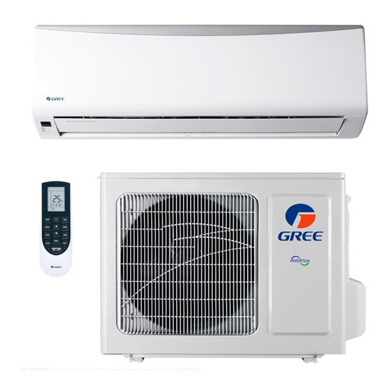
Service Manual Part Ⅰ : Technical Information 1. Summary Indoor Unit A1 panel A2 panel A5 panel GWH18QD-K3DNA5G/I(CB425N03402/CB425N03400) GWH24QE-K3DNA5G/I(CB425N03302) A5 panel GWH18QD-K3DNA5G/I(CB425N03403) GWH24QE-K3DNA5G/I(CB425N03303) A6 panel B2 panel B4 panel Technical Information... - Page 5 Service Manual B6 panel B8 panel C2 panel Outdoor Unit GWH18QD-K3DNA1G/O GWH24QE-K3DNA1G/O Remote Controller YAN1F1 Technical Information...
-
Page 6: Specifications
Service Manual 2. Specifications 2.1 Specification Sheet Parameter Unit Value 1.GWH18QD-K3DNA1G 2.GWH18QD-K3DNA5G Model 3.GWH18QD-K3DNA6G 4.GWH18QD-K3DNB4G 5.GWH18QD-K3DNB6G 1.CB419005600 2.CB425003402 CB425003403 Product Code 3.CB427004400 4.CB434002002 5.CB435000202 Rated Voltage 220-240 Power Rated Frequency Supply Phases Power Supply Mode Outdoor Cooling Capacity(Min~Max) 5130(1260~6600) Heating Capacity(Min~Max) - Page 7 Service Manual Outdoor Unit Model GWH18QD-K3DNA1G/O Outdoor Unit Product Code CB419W05600 Compressor Manufacturer ZHUHAI LANDA COMPRESSOR CO.,LTD Compressor Model QXA-B141zF030 Compressor Oil 68EP Compressor Type Rotary Compressor LRA. Compressor RLA Compressor Power Input 1440 Compressor Overload Protector 1NT11L-6233 or KSD115ºC or HPC115/95U1...
- Page 8 Service Manual Parameter Unit Value 1.GWH18QD-K3DNA1G 2.GWH18QD-K3DNA2G 3.GWH18QD-K3DNA5G 4.GWH18QD-K3DNB2G Model 5.GWH18QD-K3DNB4G 6.GWH18QD-K3DNB6G 7.GWH18QD-K3DNB8G 8.GWH18QD-K3DNC2G 1.CB419005601 2.CB426001401 3.CB425003401 4.CB432002301 Product Code 5.CB434002001 6.CB435000201 7.CB438000501 8.CB439000201 Rated Voltage 220-240 Power Rated Frequency Supply Phases Power Supply Mode Outdoor Cooling Capacity(Min~Max) 5130(1260~6600) Heating Capacity(Min~Max)
- Page 9 Service Manual Outdoor Unit Model GWH18QD-K3DNA1G/O Outdoor Unit Product Code CB419W05601 Compressor Manufacturer ZHUHAI LANDA COMPRESSOR CO.,LTD Compressor Model QXA-B141zF030 Compressor Oil 68EP Compressor Type Rotary Compressor LRA. Compressor RLA Compressor Power Input 1440 Compressor Overload Protector 1NT11L-6233 or KSD115ºC or HPC115/95U1...
- Page 10 Service Manual Parameter Unit Value 1.GWH24QE-K3DNA1G 2.GWH24QE-K3DNA2G Model 3.GWH24QE-K3DNA5G 4.GWH24QE-K3DNA6G 5.GWH24QE-K3DNB4G 6.GWH24QE-K3DNB6G 1.CB419005300 CB419005302 2.CB426001501 Product Code 3.CB425003302 CB425003303 4.CB427004500 5.CB434002202 6.CB435000303 Rated Voltage 220-240 Power Rated Frequency Supply Phases Power Supply Mode Outdoor Cooling Capacity(Min~Max) 6700(2000~8200) Heating Capacity(Min~Max) 7250(2000~8500) Cooling Power Input(Min~Max) 1875(400~3700) Heating Power Input(Min~Max)
- Page 11 Service Manual Outdoor Unit Model GWH24QE-K3DNA1G/O Outdoor Unit Product Code CB419W05300 Compressor Manufacturer ZHUHAI LANDA COMPRESSOR CO,LTD. Compressor Model QXAS-D23zX090A Compressor Oil FV50S Compressor Type Rotary Compressor LRA. Compressor RLA 11.50 Compressor Power Input 2550 Compressor Overload Protector 1NT11L-6233 or HPC115/95/ or KSD115ºC Throttling Method Electron expansion valve+Capillary Set Temperature Range...
- Page 12 Service Manual Parameter Unit Value 1.GWH24QE-K3DNA1G 2.GWH24QE-K3DNA5G 3.GWH24QE-K3DNB2G 4.GWH24QE-K3DNB4G Model 5.GWH24QE-K3DNB6G 6.GWH24QE-K3DNB8G 7.GWH24QE-K3DNC2G 1.CB419005301 2.CB425003301 3.CB432002401 4.CB434002201 Product Code 5.CB435000301 CB435000302 6.CB438000701 7.CB439000301 Rated Voltage 220-240 Power Rated Frequency Supply Phases Power Supply Mode Outdoor Cooling Capacity(Min~Max) 6700(2000~8200) Heating Capacity(Min~Max) 7250(2000~8500) Cooling Power Input(Min~Max) 1875(400~3700)
- Page 13 Service Manual Outdoor Unit Model GWH24QE-K3DNA1G/O Outdoor Unit Product Code CB419W05301 Compressor Manufacturer ZHUHAI LANDA COMPRESSOR CO,LTD. Compressor Model QXAS-D23zX090A Compressor Oil FV50S Compressor Type Rotary Compressor LRA. Compressor RLA 11.50 Compressor Power Input 2550 Compressor Overload Protector 1NT11L-6233 or HPC115/95/ or KSD115ºC Throttling Method Electron expansion valve+Capillary Set Temperature Range...
-
Page 14: Operation Characteristic Curve
Service Manual 2.2 Operation Characteristic Curve Cooling Heating 220V Conditions 220V Indoor: DB27°C/WB19°C Outdoor: DB35°C/WB24°C Indoor air flow: High Pipe length: 5m 230V 230V 240V Conditions Indoor: DB20°C/WB15°C 240V Outdoor: DB7°C/WB6°C Indoor air flow: High Pipe length: 5m 10 20 30 40 50 60 70 80 90 100 Compressor speed (rps) Compressor speed (rps) 2.3 Capacity Variation Ratio According to Temperature... -
Page 15: Cooling And Heating Data Sheet In Rated Frequency
Service Manual 2.4 Cooling and Heating Data Sheet in Rated Frequency Cooling: Rated cooling Pressure of gas pipe Inlet and outlet pipe Compressor condition(°C) connecting indoor and temperature of heat Fan speed of Fan speed of Model frequency (DB/WB) outdoor unit exchanger indoor unit outdoor unit... -
Page 16: Outline Dimension Diagram
Service Manual 3. Outline Dimension Diagram 3.1 Indoor Unit Φ55 Φ55 Φ70 Φ70 Unit:mm Model 1078 Technical Information... -
Page 17: Outdoor Unit
Service Manual 3.2 Outdoor Unit Unit:mm Technical Information... -
Page 18: Refrigerant System Diagram
Service Manual 4. Refrigerant System Diagram Outdoor unit Indoor unit Gas pipe side Valve 4-Way valve Di s charge Heat Suction Accumlator exchanger Compressor (evaporator) Heat exchanger Liquid pipe (condenser) side Valve Strainer Electric Capillary Strainer expand valve COOLING HEATING Connection pipe specification: Liquid pipe:1/4"... -
Page 19: Electrical Part
Grounding wire YEGN Yellow/Green Black Violet Orange Note: Jumper cap is used to determine fan speed and the swing angle of horizontal lover for this model. ● Indoor Unit GWH18QD-K3DNA1G/I(CB419N05600) GWH18QD-K3DNA5G/I(CB425N03400/CB425N03403) GWH18QD-K3DNA6G/I(CB427N04400) GWH18QD-K3DNB6G/I(CB435N00202) GWH24QE-K3DNA1G/I(CB419N05302) GWH24QE-K3DNA5G/I(CB425N03300/CB425N03303) GWH24QE-K3DNA6G/I(CB427N04500) GWH24QE-K3DNB4G/I(CB434N02202) GWH24QE-K3DNB6G/I(CB435N00302/CB435N00303) Technical Information... - Page 20 Service Manual GWH18QD-K3DNA1G/I(CB419N05601) GWH18QD-K3DNA2G/I(CB426N01400) GWH18QD-K3DNB6G/I(CB435N00200) GWH18QD-K3DNB2G/I(CB432N02300) GWH18QD-K3DNB4G/I(CB434N02000) GWH18QD-K3DNB8G/I(CB438N00500) GWH18QD-K3DNC2G/I(CB439N00200) GWH24QE-K3DNA1G/I(CB419N05300) GWH24QE-K3DNA2G/I(CB426N01500) GWH24QE-K3DNA5G/I(CB425N03302) GWH24QE-K3DNB2G/I(CB432N02400) GWH24QE-K3DNB4G/I(CB434N02200) GWH24QE-K3DNB6G/I(CB435N00300) GWH24QE-K3DNB8G/I(CB438N00700) GWH24QE-K3DNC2G/I(CB439N00300) ● Outdoor Unit GWH18QD-K3DNA1G/O(CB419W05600) Please don't touch any terminal when the voltage of terminal P(DC+) and N(DC-) at AP1 is higher than 30V to prevent the...
- Page 21 Service Manual GWH18QD-K3DNA1G/O(CB419W05601) Please don't touch any terminal when the voltage of terminal P(DC+) and N(DC-) at AP1 is higher than 30V to prevent the risk of electric shock ! GWH24QE-K3DNA1G/O(CB419W05300) Please don't touch any electronic component or terminal when the machine is...
- Page 22 Service Manual GWH24QE-K3DNA1G/O(CB419W05301) Please don't touch any electronic component or terminal when the machine is running , stopping or has been powered off for less than 30 minutes to prevent the risk of electric shock ! These circuit diagrams are subject to change without notice, please refer to the one supplied with the unit. Technical Information...
-
Page 23: Pcb Printed Diagram
Service Manual 5.2 PCB Printed Diagram Indoor Unit ● Top view Name Power supply live wire Communication wire Fuse Indoor fan driven capacitor Neutral wire interface of cold plasma(only for the model with this function) Neutral wire interface of power supply Interface of PG motor Live wire interface of cold plasma(only for the model... - Page 24 Service Manual Outdoor Unit ● Top view Name Terminal of compressor overload protection Terminal of temperature sensor Terminal of electronic expansion valve 4 Terminal of outdoor fan 5 Terminal of 4-way valve Terminal of compressorelectric heating Terminal of chassis electric heating Terminal of indoor unit and outdoor unit communication...
- Page 25 Service Manual ● Top view Name Power supply neutral wire Power supply live wire Communication wire with indoor unit Terminal of outdoor temperature sensor Terminal of compressor overload protection Terminal of electronic expansion valve Terminal of outdoor fan Terminal of compressor electric heating Terminal of 4-way valve Terminal of compressor...
-
Page 26: Function And Control
Service Manual 6. Function and Control 6.1 Remote Controller Introduction ON/OFF button MODE button FAN button SWING button TURBO button ▲/ button SLEEP button TEMP button I FEEL button LIGHT button CLOCK button TIMER ON / TIMER OFF button Introduction for icons on display screen Set fan speed I feel Send signal... - Page 27 Service Manual 1. ON/OFF button Press this button can turn on or turn off the air conditioner. After turning on the air conditioner, operation indicator " "on indoor unit’s display is ON (green indicator. The colour is different for different models), and indoor unit will give out a sound. 2.
- Page 28 Service Manual 7. SLEEP button Under COOL, HEAT or DRY mode, press this button to start up sleep function. " " icon is displayed on remote controller. Press this button again to cancel sleep function and " " icon will disappear. 8.
-
Page 29: Function Introduction For Combination Buttons
Service Manual Function introduction for combination buttons 1. Energy-saving function Under cooling mode, press "TEMP" and " CLOCK" buttons simultaneously to start up or turn off energy-saving function. When energy-saving function is started up, "SE" will be shown on remote controller, and air conditioner will adjust the set temperature automatically according to ex-factory setting to reach to the best energy-saving effect. -
Page 30: Brief Description Of Modes And Functions
Service Manual 6.2 Brief Description of Modes and Functions 1.Basic function of system (1)Cooling mode (1) Under this mode, fan and swing operates at setting status. Temperature setting range is 16~30 (2) During malfunction of outdoor unit or the unit is stopped because of protection, indoor unit keeps original operation status. (2)Drying mode (1) Under this mode, fan operates at low speed and swing operates at setting status. - Page 31 Service Manual (8)I feel control mode After controller received I feel control signal and ambient temperature sent by remote controller, controller will work according to the ambient temperature sent by remote controller. (9)Compulsory defrosting function (1) Start up compulsory defrosting function Under ON status, set heating mode with remote controller and adjust the temperature to 16 C.
-
Page 32: Outdoor Units
Service Manual Outdoor Units 1. Input Parameter Compensation and Calibration (1) Check the ambient temperature compensation function Indoor ambient temperature compensation function. a. In cooling mode, the indoor ambient temperature participating in computing control = (T – ⊿ T indoor ambient temperature cooling indoor ambient temperature compensation b. - Page 33 Service Manual 3. Special Functions Defrosting Control ① Conditions for starting defrosting After the time for defrosting is judged to be satisfied, if the temperature for defrosting is satisfied after detections for continuous 3minutes, the defrosting operation will start. ② Conditions of finishing defrosting The defrosting operation can exit when any of the conditions below is satisfied: ③...
- Page 34 Service Manual 1. Starting estimation: After the compressor stopped working for 180s, if T >[T (the temperature of hysteresis is 2 )], the inner pipe frozen-preventing frequency-limited temperature machine is only allowed to start for operating, otherwise it should not be started, and should be stopped to treat according to the frozen- preventing protection: Clear the trouble under the mode of power turn-off / heating, and the protection times are not counted.
- Page 35 Service Manual 1. Frequency limited If [T ]≤T <[T ] , you should limit the frequency raising of heating overload frequency-limited temperature inner pipe heating overload frequency reducing temperature at normal speed compressor. 2. Reducing frequency at normal speed and stopping machine: If T[ ]≤T <[T...
- Page 36 Service Manual (6)Voltage sag protection After start the compressor, if the time of DC link Voltage sag [U ] is measured to be less than t Voltage sag protection time , Sagging protection voltage the machine should be stop at once, hand on the voltage sag trouble, reboot automatically after 30 minutes. (7)Communication fault When you have not received any correct signal from the inner machine in three minutes, the machine will stop for communication fault.
- Page 37 Service Manual (12) Starting-up Failure Protection for Compressor Stop the compressor after its starting-up fails, restart it after 20s if the fault doesn’t shows, and if they are all failing for the successive start 3 times, it shall be reported as Starting-up Failure, and then restart up it after 3 min. When it still not be able to operate through carry out the above process for 5 times, it is available if press ON/OFF.
- Page 38 Service Manual 6. Electric Heating Function of Chassis (1) When T ≤0ºC, the electric heating of chassis will operate; outdoor amb. (2) When T >2ºC, the electric heating of chassis will stop operation; outdoor amb. (3)When 0ºC<T ≤2ºC, the electric heating of chassis will keep original status. outdoor amb.
-
Page 39: Part Ⅱ : Installation And Maintenance
Service Manual Part Ⅱ : Installation and Maintenance 7. Notes for Installation and Maintenance Safety Precautions: 10. If the power cord or connection wire is not long enough, please get the specialized power cord or connection wire Important! from the manufacture or distributor. Prohibit prolong the wire by yourself. - Page 40 Service Manual Main Tools for Installation and Maintenance 1. Level meter, measuring tape 2. Screw driver 3. Impact drill, drill head, electric drill 4. Electroprobe 5. Universal meter 6. Torque wrench, open-end wrench, inner hexagon spanner 7. Electronic leakage detector 8.
-
Page 41: Installation
Service Manual 8. Installation 8.1 Installation Dimension Diagram Space to the wall Space to the wall At least 15cm At least 15cm Drainage pipe Installation and Maintenance... - Page 42 Service Manual Installation procedures Start installation Preparation before installation Read the requirements select installation Prepare tools for electric connection location Select indoor unit Select outdoor unit installation location installation location Install the support of outdoor unit Install wall-mounting (select it according to the actual situation) frame, drill wall holes Connect pipes of indoor Fix outdoor unit...
-
Page 43: Installation Parts-Checking
Service Manual 8.4 Electric Connection Requirement 8.2 Installation Parts-checking 1. Safety Precaution Name Name (1) Must follow the electric safety regulations when installing Indoor unit Sealing gum the unit. Outdoor unit Wrapping tape (2) According to the local safety regulations, use qualified Support of outdoor power supply circuit and air switch. - Page 44 Service Manual in the holes. 4. Outlet Pipe (3) Fix the wall-mounting frame on the wall with tapping screws (1) The pipe can be led out in the direction of right, rear right, (ST4.2X25TA) and then check if the frame is firmly installed by left or rear left.(As show in Fig.3) pulling the frame.
- Page 45 Service Manual (4) Put wiring cover back and then tighten the screw. (5) Close the panel. Drain hose Outlet pipe Note: (1) All wires of indoor unit and outdoor unit should be connected by a professional. Tape Drain hose (2) If the length of power connection wire is insufficient, please Outlet Fig.9 pipe...
-
Page 46: Installation Of Outdoor Unit
Service Manual 4. Connect Indoor and Outdoor Pipes Outdoor Indoor (1) Remove the screw on the handle and valve cover of outdoor Fig.17 Wall pipe Sealing gum unit and then remove the handle and valve cover.(As show in Fig.21) Upper hook (2) Remove the screw cap of valve and aim the pipe joint at the bellmouth of pipe.(As show in Fig.22) Liquid pipe... -
Page 47: Vacuum Pumping And Leak Detection
Service Manual 2. Leakage Detection The drain hos (1) With leakage detector: can't raise upwards Check if there is leakage with leakage detector. (2) With soap water: Wall If leakage detector is not available, please use soap water for leakage detection. Apply soap water at the suspected position Fig.25 and keep the soap water for more than 3min. -
Page 48: Maintenance
Service Manual 9. Maintenance 9.1 Malfunction Display of Indoor Unit 1. Malfunction display requirement When there are several malfunctions, they will be displayed circularly. 2. Malfunction display method (1) Hardware malfunction: immediate display; refer to “malfunction display table”; (2) Operation state: immediate display; refer to “malfunction display table”; (3) Other malfunctions: it is displayed after the compressor stops for 200s;... - Page 49 Service Manual ●Discharging method (1) remove the inverter cover(Outdoor Unit) Inverter cover P.C.board (Soldered surface) (2)As shown below,connect the discharge resistance(approx.100Ω20W)or plug of the sold ering iron to voltage between + - terminals of the electrolytic capacitor on PC Board for 30s, and then peformedischarging. NOTE: A large-capacity electrolytic capacitor is used in the outdoor unit controller(inverter).Therefore,if the power supply is turned off,charge(charging voltage DC280V to 380V)remains and disc harging takes a lot of time..
-
Page 50: Procedure Of Troubleshooting
Service Manual 9.2 Procedure of Troubleshooting Indoor unit (1) Malfunction of Temperature Sensor F1, F2 Main detection points: ● Is the wiring terminal between the temperature sensor and the controller loosened or poorly contacted? ● Is there short circuit due to trip-over of the parts? ●... - Page 51 Service Manual (2) Malfunction of Blocked Protection of IDU Fan Motor H6 Main detection points: ● SmoothlyIs the control terminal of PG motor connected tightly? ● SmoothlyIs the feedback interface of PG motor connected tightly? ● The fan motor can't operate? ●...
- Page 52 Service Manual (3) Malfunction of Protection of Jumper Cap C5 Main detection points: ● Is there jumper cap on the mainboard? ● Is the jumper cap inserted correctly and tightly? ● The jumper is broken? ● The motor is broken? ●...
- Page 53 Service Manual (4) Malfunction of Zero-crossing Inspection Circuit Malfunction of the IDU Fan Motor U8 Main detection points: ● Instant energization afte de-energization while the capacitordischarges slowly? ● The zero-cross detectioncircuit of the mainboard is defined abnormal? Malfunction diagnosis process: Start Turn power off for 1minute,the turn...
- Page 54 Service Manual (5) Communication malfunction (E6) Troubleshooting for E6 malfunction Disconnect power and check if the connection wire of indoor and outdoor units and the built-in wire of electric box are correctly connected. Connect the wire properly according Is malfunction Correct connection? to the wiring eliminated?
- Page 55 Service Manual Outdoot Unit (1) Malfunction of Desynchronizing of Compressor (H7) Main check point: Whether the system pressure is too high? Whether the electronic expansion valve can work normally? Whether the radiation for the unit is in good condition? Malfunction diagnosis process: Desynchronizing malfunction occurs after de-energizing and turning on the unit...
- Page 56 Service Manual Desynchronizing malfunction occurs during operation process Check whether Whether the outdoor fan can Replace fan capacitor the fan terminal is operate normally? connected well Improve the radiation circumstances for the Whether the radiation for the unit (such as clean heat unit is in good condition? Replace outdoor fan exchanger, improve...
- Page 57 Service Manual (2) Malfunction of Temperature Sensor (F3/F4/F5) Main check point: Whether the temperature sensor is damaged? Whether the terminal of temperature sensor is loose or not connected? Whether the main board is damaged? Malfunction diagnosis process: Start the troubleshooting for temperature sensor Check the connection between temperature sensor and wiring...
- Page 58 Service Manual (3) Malfunction of Overload Protection of Compressor (H3) and Discharge High-temperature Protection of Compressor (E4) Main check point: Whether the electronic expansion valve is connected well and whether it’s damaged? Whether the refrigerant is leaking? Whether the overload protector is damaged? Start Malfunction diagnosis process: Whether the overload protector is...
- Page 59 Service Manual (4) Charging Malfunction of Capacitor (PU) Main check point: Whether input power is normal? Main board is damaged. Malfunction diagnosis process: Energize and turn on the unit; wait for 1 min Measure the voltage at both ends of big electrolytic capacitor with the DC notch of universal meter There is malfunction for the...
- Page 60 Service Manual (5) Malfunction of Overload Protection (E8) Main check point: Whether the tube temperature sensor is normal? Whether the outdoor ambient temperature is within the normal range? Whether indoor fan and outdoor fan can operate normally? Whether radiation environment inside or outside the unit is good? Malfunction diagnosis process: Start Replace the tube temperature...
- Page 61 Service Manual (6) Malfunction of IPM Protection (H5) Main check point: Whether input voltage is within the normal range? Whether wires of compressor are connected reliably, tightly or correctly? Whether the resistance of compressor coil is normal? Whether the insulation between compressor coil and copper pipe is in good condition? Whether the unit is overloading? Whether the radiation for the unit is in good condition? Whether the volume of charged refrigerant is proper?
- Page 62 Service Manual (7) Malfunction of PFC Protection (HC) Main check point: Whether power supply is normal? Malfunction diagnosis process: Start Check whether power supply is normal Turn on the unit again after the power is Is power abnormal? resumed Replace main board of outdoor unit Installation and Maintenance...
- Page 63 Service Manual (8) Malfunction of Communication (E6) Main check point: Check whether connection wires between indoor unit and outdoor unit and wiring inside the unit are connected well? Check the main board of indoor unit or main board of outdoor unit is damaged? Malfunction diagnosis process: Communication malfunction De-energize the unit and then...
- Page 64 Service Manual (9) Malfunction of Failure Start-up of Compressor (LC) Main check point: Whether the compressor wires are connected correctly? Whether the stop time for compressor is enough? Whether compressor is damaged? Whether the refrigerant-charging volume is superfluous? Malfunction diagnosis process: Energize and turn on the unit Whether the stop time for...
- Page 65 Service Manual (10) Malfunction of Overcurrent Protection E5 Main detection points: ● Is the supply voltage unstable with big fluctuation? ● Is the supply voltage too low with overload? ● Hardware trouble? Malfunction diagnosis process: Start Normal fluctuation should be within 10 % Is malfunction Is the supply voltage unstable of the rated voltage on the nameplate...
- Page 66 Service Manual (9) Other Malfunction 1.IPM module temperature sensor is open-circuited (P7) Hardware of main board is damaged. Please replace main board. 2.Overheating protection of IPM module (P8) ① Poor radiation because the module radiator is dirty; ② IPM module is damaged; ③...
-
Page 67: Troubleshooting For Normal Malfunction
Service Manual 9.3 Troubleshooting for Normal Malfunction 1. Air Conditioner Can't be Started Up Possible Causes Discriminating Method (Air conditioner Status) Troubleshooting Confirm whether it's due to power failure. If yes, No power supply, or poor After energization, operation indicator isn’t bright wait for power recovery. - Page 68 Service Manual 4. ODU Fan Motor Can't Operate Possible causes Discriminating method (air conditioner status) Troubleshooting Connect wires according to wiring diagram to Wrong wire connection, or poor Check the wiring status according to circuit make sure all wiring terminals are connected connection diagram firmly...
-
Page 69: Exploded View And Parts List
Service Manual 10. Exploded View and Parts List 10.1 Indoor Unit GWH18QD-K3DNA1G/I GWH18QD-K3DNA2G/I GWH18QD-K3DNA5G/I(CB425N03403) GWH18QD-K3DNA6G/I GWH18QD-K3DNB6G/I GWH18QD-K3DNC2G/I Installation and Maintenance... - Page 70 Service Manual Part Code Description GWH18QD-K3DNA1G/I GWH18QD-K3DNA1G/I Product Code CB419N05600 CB419N05601 Decorative Strip 20192613 20192613 Front Panel 20022481S 20022481S Display Board 30565233 30565233 Filter Sub-Assy 11122089 11122089 Decorative Board (Left) 20192612 20192612 Front Case 20022484 20022484 Guide Louver 10512734 10512734...
- Page 71 Service Manual Part Code Description GWH18QD-K3DNA2G/I GWH18QD-K3DNA5G/I Product Code CB426N01400 CB425N03403 Decorative Strip 20192673 20192703K Front Panel 2002270101 2002266902 Display Board 30565264 30565269 Filter Sub-Assy 11122089 11122089 Decorative Board (Left) 2019267001 2019261201 Front Case 2002248401 2002248401 Guide Louver 1051276501 1051273402 Axile Bush 10542036 10542036...
- Page 72 Service Manual Part Code Description GWH18QD-K3DNB6G/I Product Code CB435N00200 CB435N00202 Decorative Strip Front Panel 20000300040S 20000300040S Display Board 30565278 30565278 Filter Sub-Assy 11122089 11122089 Decorative Board (Left) 20192662 20192662 Front Case 2002248401 2002248401 Guide Louver 1051276501 1051276501 Axile Bush 10542036 10542036 Air Louver 10512732...
- Page 73 Service Manual Part Code Description GWH18QD-K3DNC2G/I GWH18QD-K3DNA6G/I Product Code CB439N00200 CB427N04400 Decorative Strip Front Panel 20000300070 2002269501 Display Board 30565278 30565264 Filter Sub-Assy 11122089 11122089 Decorative Board (Left) 20192662 2019267001 Front Case 2002248401 2002248401 Guide Louver 1051276501 1051276501 Axile Bush 10542036 10542036 Air Louver...
- Page 74 Service Manual GWH24QE-K3DNA1G/I GWH24QE-K3DNA5G/I(CB425N03303) GWH24QE-K3DNA6G/I GWH24QE-K3DNB6G/I GWH24QE-K3DNC2G/I Installation and Maintenance...
- Page 75 Service Manual Part Code Description GWH24QE-K3DNA1G/I GWH24QE-K3DNA1G/I Product Code CB419N05300 CB419N05302 Front Panel Assy 20022491 20022491 Filter Sub-Assy 11012007 11012007 Screw Cover 24252453 24252453 Front Case Assy 20022487 20022487 Air Louver(Manual) 10512737 10512737 Helicoid Tongue 26112513 26112513 Left Axile Bush 10512037 10512037 Rear Case assy...
- Page 76 Service Manual Part Code Description GWH24QE-K3DNB6G/I GWH24QE-K3DNB6G/I Product Code CB435N00302 CB435N00300 Front Panel Assy 20000300048 20000300048 Filter Sub-Assy 11012007 11012007 Screw Cover 2425245301 2425245301 Front Case Assy 00000200043 00000200043 Air Louver(Manual) 10512737 10512737 Helicoid Tongue 26112513 26112513 Left Axile Bush 10512037 10512037 Rear Case assy...
- Page 77 Service Manual Part Code Description GWH24QE-K3DNA2G/I GWH24QE-K3DNA5G/I Product Code CB426N01500 CB425N03303 Front Panel Assy 00000300037 00000300004 Filter Sub-Assy 11012007 11012007 Screw Cover 2425245301 2425245301 Front Case Assy 00000200024 00000200013 Air Louver(Manual) 10512737 10512737 Helicoid Tongue 26112513 26112513 Left Axile Bush 10512037 10512037 Rear Case assy...
- Page 78 Service Manual Part Code Description GWH24QE-K3DNA6G/I GWH24QE-K3DNB6G/I Product Code CB427N04500 CB435N00303 Front Panel Assy 2002270001 20000300048 Filter Sub-Assy 11012007 11012007 Screw Cover 2425245301 2425245301 Front Case Assy 00000200024 00000200043 Air Louver(Manual) 10512737 10512737 Helicoid Tongue 26112513 26112513 Left Axile Bush 10512037 10512037 Rear Case assy...
- Page 79 Service Manual Part Code Description GWH24QE-K3DNC2G/I Product Code CB439N00300 Front Panel Assy 20000300071 Filter Sub-Assy 11012007 Screw Cover 2425245301 Front Case Assy 00000200043 Air Louver(Manual) 10512737 Helicoid Tongue 26112513 Left Axile Bush 10512037 Rear Case assy 22202570 Rubber Plug (Water Tray) 76712012 Ring of Bearing 26152025...
- Page 80 Service Manual GWH18QD-K3DNA5G/I(CB425N03400/CB425N03402) GWH18QD-K3DNB2G/I GWH18QD-K3DNB8G/I GWH24QE-K3DNA5G/I(CB425N03302) GWH24QE-K3DNB2G/I GWH24QE-K3DNB8G/I Installation and Maintenance...
- Page 81 Service Manual Part Code Description GWH18QD-K3DNA5G/I GWH18QD-K3DNA5G/I Product Code CB425N03400 CB425N03402 Front Panel 2002266902 2002266902 Filter Sub-Assy 11122089 11122089 Screw Cover 2425201726 2425201726 Front Case Assy 00000200023 00000200023 Air Louver(Manual) 10512732 10512732 Helicoid Tongue 26112512 26112512 Left Axile Bush 10512037 10512037 Rear Case assy 22202571...
- Page 82 Service Manual Part Code Description GWH18QD-K3DNB2G/I GWH18QD-K3DNB8G/I Product Code CB432N02300 CB438N00500 Front Panel 20000300023 20000300075 Filter Sub-Assy 11122089 11122089 Screw Cover 2425201726 2425201726 Front Case Assy 00000200042 00000200042 Air Louver(Manual) 10512732 10512732 Helicoid Tongue 26112512 26112512 Left Axile Bush 10512037 10512037 Rear Case assy 22202571...
- Page 83 Service Manual Part Code Description GWH24QE-K3DNA5G/I GWH24QE-K3DNA5G/I Product Code CB425N03302 CB425N03300 Front Panel 2002267401 2002267401 Filter Sub-Assy 11012007 11012007 Screw Cover 2425245301 2425245301 Front Case Assy 00000200013 00000200013 Air Louver(Manual) 10512737 10512737 Helicoid Tongue 26112513 26112513 Left Axile Bush 10512037 10512037 Rear Case assy 22202570...
- Page 84 Service Manual Part Code Description GWH24QE-K3DNA5G/I GWH24QE-K3DNB2G/I Product Code CB425N03302 CB432N02400 Front Panel 2002267401 20000300016 Filter Sub-Assy 11012007 11012007 Screw Cover 2425245301 2425245301 Front Case Assy 00000200013 00000200043 Air Louver(Manual) 10512737 10512737 Helicoid Tongue 26112513 26112513 Left Axile Bush 10512037 10512037 Rear Case assy 22202570...
- Page 85 Service Manual Part Code Description GWH24QE-K3DNB8G/I Product Code CB438N00700 Front Panel 20000300076 Filter Sub-Assy 11012007 Screw Cover 2425245301 Front Case Assy 00000200043 Air Louver(Manual) 10512737 Helicoid Tongue 26112513 Left Axile Bush 10512037 Rear Case assy 22202570 Rubber Plug (Water Tray) 76712012 Ring of Bearing 26152025...
- Page 86 Service Manual GWH18QD-K3DNB4G/I GWH24QE-K3DNB4G/I Installation and Maintenance...
- Page 87 Service Manual Part Code Description GWH24QE-K3DNB4G/I GWH24QE-K3DNB4G/I Product Code CB434N02202 CB434N02200 Front Panel 20000300029 20000300029 Filter Sub-Assy 11012007 11012007 Screw Cover 2425245301 2425245301 Front Case Assy 00000200043 00000200043 Air Louver(Manual) 10512737 10512737 Helicoid Tongue 26112513 26112513 Left Axile Bush 10512037 10512037 Rear Case assy 22202570...
- Page 88 Service Manual Part Code Description GWH18QD-K3DNB4G/I Product Code CB434N02000 Front Panel 20000300028 Filter Sub-Assy 11122089 Screw Cover 2425201726 Front Case Assy 00000200042 Air Louver(Manual) 10512732 Helicoid Tongue 26112512 Left Axile Bush 10512037 Rear Case assy 22202571 Rubber Plug (Water Tray) 76712012 Ring of Bearing 26152025...
- Page 89 Service Manual 10.2 Outdoor Unit Installation and Maintenance...
- Page 90 Service Manual Part Code Description GWH18QD-K3DNA1G/O GWH18QD-K3DNA1G/O Product Code CB419W05600 CB419W05601 Front Grill 22413025 22413025 Front Panel 01535013 01535013 Drainage Connecter 06123401 06123401 Chassis Sub-assy 02803231P 02803270P Drainage hole Cap 06813401 06813401 Compressor and fittings 00105246G 00105246G Magnet Coil 4300040045...
- Page 91 Service Manual Part Code Description GWH24QE-K3DNA1G/O GWH24QE-K3DNA1G/O Product Code CB419W05300 CB419W05301 Front Grill 22413025 22413025 Front Panel 01535013P 01535013P Drainage Connecter 06123401 06123401 Chassis Sub-assy 01205816P 0120581601P Drainage hole Cap 06813401 06813401 Compressor and fittings 0010505701 0010505701 Magnet Coil 4300040078 4300040078 4-Way Valve Assy 03073274...
-
Page 92: Removal Procedure
Service Manual 11. Removal Procedure Caution: discharge the refrigerant completely before removal. 11.1 Removal Procedure of Indoor Unit 1.Remove fifter assy Front panel Open the front panel. Push the left and rightfilters to make them break away from thegroove on the front case. Then remove the leftand right filters one by one. - Page 93 Service Manual 4.Remove electric box cover 2 Remove the screw on the electric box cover 2 to remove the electric box cover 2. Electric box cover 2 5.Remove front case sub-assy Remove the screws fixing front case. Note: ① Open the screw caps before removing the screws arround the air outlet.
- Page 94 Service Manual Step Procedure 7.Remove vertical louver Loosen the connection clasps between vertical louver and bottom case to remove vertion louver. Swing motor Screw off the screws that are locking the swing motor and take the motor off. 8.Remove electric box assy Loosen the connection clasps between shield cover of electric box sub-assy and electric box,and then remove the shield...
- Page 95 Service Manual Step Procedure Rotate the electric box assy. Twist off the screws Rotate the electric box assy. Twist offthe that are locking the wire clip and loosen the Screws screwsthat are locking the wire clip and power cord. Remove the wiring terminal of loosen the power cord.
- Page 96 Service Manual Step Procedure Adjust the position of conncetion pipe on evaporator up wards to remove it. 10.Remove motor and cross flow blade Remove the screws fixing motor clamp and then remove the motor clamp. ① Remove the screws at the connection place of cross flow blade and motor;...
-
Page 97: Removal Procedure Of Outdoor Unit
Service Manual 11.2 Removal Procedure of Outdoor Unit Warning: Be sure to wait for a minimum of 20 minutes after turning off all power supplies and discharge the refrigerant completely before removal. Step Procedure 1. Remove big handle,valve cover and top cover handle Remove the screw connecting the big handle and right side plate, and then remove the big... - Page 98 Service Manual Step Procedure 2. Remove grille and cabinet screws Remove the 4 screws connecting the grille and outer case, and then remove the panel grille. grille Remove the screws connecting the outer case with motor support, isolation plate and chassis; screws lift the outer case upwards;...
- Page 99 Service Manual Step Procedure 4. Remove axial flow blade Remove the nut fixing axial flow blade and then remove the blade. axial flow blade 5.Remove electric box assy grounding wire Remove the grounding wire screw on the e l e c t r i c b o x a s s y a n d t h e n r e m o v e t h e grounding wire.
- Page 100 Service Manual Step Procedure screws Remove the 2 screws fixing the electric box assy and then lift the electric box assy upwards to remove it. electric box assy electric box clasp(right) cover clasp(left) Push the electric box cover in the direction of arrow to make the clasp at the right side separate from the groove;...
- Page 101 Service Manual Step Procedure 6.remove the soundproof sponge. Tear off the sticking stripe and then remove the soundproof sponge. sticking stripe soundproof sponge 7.remove the isolation plate and reactor Remove the 2 screws connecting the isolation plate and condenser side plate; remove the 3 screws connecting the isolation plate and chassis, and then remove the isolation plate.
- Page 102 Service Manual Step Procedure 8.Valve Support Sub-Assy valve support Unsolder the welding joint connecting the valve sub-Assy with capillary and condenser; unsolder the welding joint connecting the gas valve and air- liquid return pipe; remove the 2 bolts fixing the gas valve valve to remove the gas valve.
- Page 103 Service Manual Step Procedure Remove the 6 screws fixing the motor and then remove the motor. motor screws 11.Remove condenser condenser Remove the 2 screws fixing the condenser and chassis, and then lift the condenser upwards to remove it. screw screw 12.Remove compressor foot nuts...
-
Page 104: Appendix
Service Manual Appendix: Appendix 1: Reference Sheet of Celsius and Fahrenheit Conversion formula for Fahrenheit degree and Celsius degree: Tf=Tcx1.8+32 Set temperature Fahrenheit Fahrenheit Fahrenheit display Fahrenheit display Fahrenheit display Fahrenheit Celsius( Celsius( Celsius( temperature temperature temperature 60.8 69/70 69.8 78/79 78.8 62/63... -
Page 105: Appendix 3: Pipe Expanding Method
Service Manual Appendix 3: Pipe Expanding Method Pipe Note: Pipe cutter Improper pipe expanding is the main cause of refrigerant leakage.Please expand the pipe according to the following steps: Leaning Uneven Burr A:Cut the pip ● Confirm the pipe length according to the distance of indoor unit and outdoor unit. ●... -
Page 106: Appendix 4: List Of Resistance For Temperature Sensor
Service Manual Appendix 4: List of Resistance for Temperature Sensor Resistance Table of Ambient Temperature Sensor for Indoor and Outdoor (15K) Temp( C) Resistance(kΩ) Temp( C) Resistance(kΩ) Temp( Resistance(kΩ) Temp( Resistance(kΩ) 138.1 18.75 3.848 1.071 128.6 17.93 3.711 1.039 121.6 17.14 3.579 1.009... - Page 107 Service Manual Resistance Table of Tube Temperature Sensors for Indoor and Outdoor (20K) Temp( C) Resistance(kΩ) Temp( C) Resistance(kΩ) Temp( Resistance(kΩ) Temp( Resistance(kΩ) 181.4 25.01 5.13 1.427 171.4 23.9 4.948 1.386 162.1 22.85 4.773 1.346 153.3 21.85 4.605 1.307 20.9 4.443 1.269 137.2...
- Page 108 Service Manual Resistance Table of Discharge Temperature Sensor for Outdoor (50K) Temp( C) Resistance(kΩ) Temp( Resistance(kΩ) Temp( C) Resistance(kΩ) Temp( Resistance(kΩ) 853.5 18.34 4.75 799.8 93.42 17.65 4.61 89.07 16.99 4.47 703.8 84.95 16.36 4.33 660.8 81.05 15.75 4.20 620.8 77.35 15.17 4.08...
- Page 109 GREE ELECTRIC APPLIANCES,INC.OF ZHUHAI Add: West Jinji Rd, Qianshan, Zhuhai, Guangdong, China 519070 Tel: (+86-756) 8522218 Fax: (+86-756) 8669426 Email: gree@gree.com.cn Http://www.gree.com HONG KONG GREE ELECTRIC APPLIANCES SALES LIMITED Add: Unit 2612,26/F.,Miramar Tower 132 Nathan Road,TST,Kowloon,HK Tel: (852) 31658898 Fax: (852) 31651029...
Need help?
Do you have a question about the GWH18QD-K3DNA1G and is the answer not in the manual?
Questions and answers