Table of Contents
Advertisement
Quick Links
Advertisement
Table of Contents

Related Manuals for Citizen CLP-9301


Summary of Contents for Citizen CLP-9301
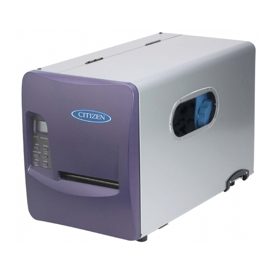
- Page 1 CLP-9001/9301 User’s Manual...
-
Page 2: Fcc Compliance Statement
FCC COMPLIANCE STATEMENT FOR AMERICAN USERS This equipment has been tested and found to comply with the limits for a Class A digital device, pursuant to Part 15 of the FCC Rules. These limits are designed to provide reasonable protection against harmful interference when the equipment is operated in a commercial environment. -
Page 3: Emi Compliance Statement For Canadian Users
EMI COMPLIANCE STATEMENT FOR CANADIAN USERS lass A digital apparatus complies with Canadian This C This equipment generates and uses radio frequency energy and if not installed and used properly, that is, in strict accordance with the manufacturer's instructions, may cause interference to radio and television reception. -
Page 4: Important Safety Instructions
Important Safety Instructions 1. Read all of these instructions and save them for later reference. 2. Follow all warnings and instructions marked on the product. 3. Unplug this product from the wall outlet before cleaning. Do not use liquid or aerosol cleaners. Use a damp cloth for cleaning. -
Page 5: Notice
7. We are not liable for any damage caused by user's erroneous use of the printer and inadequate environment. 8. Data residing in the printer is temporary. Therefore, all data will be lost if power is lost. We are not liable for any damage or loss of profits caused by data loss due to failures, repairs, inspections, etc. -
Page 6: Introduction
This manual is designed to help you quickly understand the basic operations of this printer. Design features This printer is designed to accurately print bar codes and various character fonts on media such as tags and labels at high speeds. Both direct thermal and thermal transfer printing is possible. -
Page 7: Table Of Contents
1.1 Checking items inside the accessory box...2 Chapter 2 Safety Precautions...3 Safety signs...3 Installation precautions ...8 Chapter 3 Names and Functions of Printer Parts...9 3.1 Printer main body ...9 3.2 Control panel ...12 Chapter 4 Media (Paper) and Ribbon...15 4.1 Types of media ...15 4.2 Paper size ...18... - Page 8 Chapter 6 Configuring Your Printer Using the Menus ...37 6.1 The Group Menu ...37 6.2 Page Setup Menu ...38 6.3 System Setup Menu...39 6.4 After Print Menu ...41 6.5 Interface Setup Menu...42 6.6 Permanently Saving Settings Menu...43 6.7 Test Mode Menu...43 6.8 Menu Mode Description ...44...
- Page 9 − − viii...
-
Page 10: Chapter 1 Unpacking
Chapter Unpacking First open the carton and take out the accessory box and the printer front cover, then lift the printer main body out of the carton, holding the bottom of the printer firmly. Also keep the carton and packing materials as the printer must be packed properly with the carton and packing materials for future shipment. -
Page 11: Checking Items Inside The Accessory Box
Chapter 1 Unpacking 1.1 Checking items inside the accessory box First, you should check that all of the following items are inside the accessory box. If any are missing, please contact your supplier. • Power cord • Paper core adaptor (3-inch) •... -
Page 12: Chapter 2 Safety Precautions
Safety signs The various safety signs included in this manual and pasted on the printer are intended to inform you of the correct and safe handling of this printer and protect against personal injury and property damage. - Page 13 Do not put containers filled with water or chemical liquids such as vases and cups near the printer. If a liquid spills or enters the printer, turn off the power switch immediately, remove the plug of the power cord from the outlet, and contact our service personnel.
-
Page 14: Power Cord
If the printer is dropped or damaged If you accidentally drop or damage the printer, turn off the power switch immediately, remove the plug of the power cord from the outlet, and contact our service personnel. - Page 15 When placing the printer on a floor or desk, be careful not to catch your fingers and hands under the feet of the printer. Never operate the power switch or insert/remove the power or data cord with wet fingers.
- Page 16 When loading the paper and ribbon, be careful not to catch your fingers in the mechanism. No use for long periods When the printer is not used for long periods, the plug of the power cord should be removed from the outlet to ensure safety. Printer care and cleaning Whilst performing maintenance and cleaning, the plug of the power cord should be removed from the outlet to ensure safety.
-
Page 17: Installation Precautions
Chapter 2 Safety Precautions Installation precautions After reading and understanding the safety signs, install the printer, observing the following precautions: Avoid dust Install away from high power-consuming equipment such as compressors and generators Avoid direct sunlight Dust can stop the printer from cleanly printing a document. It can also cause breakdowns and shorten the printer life. -
Page 18: Chapter 3 Names And Functions Of Printer Parts
To remove the front cover, first open it fully then vertically lift up the hinged left side of the cover. -
Page 19: Control Panel
Chapter 3 Names and Functions of Printer Parts 1 Front cover 2 Right side cover 3 Control panel 4 Printhead lever 5 Printhead 6 Printhead pressure knob 7 Platen 8 Right side cover grip 9 Paper guide roller 10 Paper guide roller release lever... - Page 20 21 Power switch 22 Parallel interface connector (or optional IEEE1284ECP or Ethernet interface connector) 23 RS-232C serial interface connector 24 (not used) 25 Optional USB interface slot plate 26 (not used) Chapter 3 Names and Functions of Printer Parts − −...
-
Page 21: Control Panel
READY LED • Lights up when the printer is placed into the print ready state. When the PAUSE key is pressed, the READY LED goes out and shows “Pause” on the LCD (Display). By pressing the PAUSE key again, the READY LED lights up. -
Page 22: Control Keys
MODE key When the MODE key is pressed, the printer is placed into the Ready mode. When the MODE key is pressed again, the printer is placed into the Menu mode. Each time the MODE key is pressed, the printer toggles between the Ready mode and Menu mode. - Page 23 Chapter 3 Names and Functions of Printer Parts MODE key Printer enters the Menu mode, and the ‘∗ Page Setup’ menu is shown on the LCD (Display). (See P31) Key functions in the Menu mode MENU key Selects the next Group Menu or Menu Item. (See P31 − 33) UP key •...
- Page 24 Chapter 4 Media (Paper) and Ribbon − −...
-
Page 25: Chapter 4 Media (Paper) And Ribbon
Chapter Media (Paper) and Ribbon This chapter describes all of the types of media available for this printer and how to load the media and ribbon. Unless otherwise specified, the term ‘media,’ ‘paper,’ ‘page,’ ‘labels’ or ‘tags’ is referring to any media that is being printed using the printer. - Page 26 Chapter 4 Media (Paper) and Ribbon ♦ Center-punched hole tag Holes (2.5mm diameter) are perforated lengthwise along the central line of the tag. ♦ Black mark tag Black marks are printed on the back of the tag at the center or on the right side in the direction of feed.
- Page 27 Chapter 4 Media (Paper) and Ribbon Label Media with adhesive material on the back are referred to as labels. Labels are peeled off the liner piece by piece and stuck to a product or item. ♦ Labels with inter-label gap There are gaps between labels.
-
Page 28: Paper Size
17.8 (0.70) 115 (4.53) 51.5 (2.02) 17.8 (0.70) Continuous paper Black mark detection Printable area Black-mark (back) OD value: 1.5 or more Ink containing carbon Use of black mark sensor Direction of paper feed W: 104.0mm for CLP-9301 101.8mm for CLP-9001... -
Page 29: Loading The Paper
4.3 Loading the paper The out-wound roll of paper is the standard, although inward-wound media can also be used. See Page 23 for details. The paper core diameters for the roll of paper are 1, 3, or 4 inches. The standard core sizes are 1 and 3 inches. - Page 30 Chapter 4 Media (Paper) and Ribbon Move the blue printhead lever towards the back of the printer to lift the printhead block. Push the blue paper guide roller release lever to lift the paper guide roller, and lower the paper guide.
- Page 31 At this time, be careful about the direction of the plate the shorter side should face down when the printer is the standard model, and up when the printer is equipped with the peeler option. Paper roll shaft SUGGESTION •...
- Page 32 Slide the blue paper guide to the edge of the roll of paper in the direction of feed and turn it upwards. Slightly pulling the paper toward you, move the blue printhead lever towards the front of the printer to lower and lock the printhead block in place.
- Page 33 When the inward-wound roll of paper is used, first put the roll of paper onto the paper roll shaft so that it can be wound clockwise as shown blow, then pull the end of the roll of paper through the printer as before. CAUTION The maximum outer diameter of the inward-wound roll of paper is 250 mm (9.84 in).
-
Page 34: Loading The Ribbon
We recommend that you should use a genuine Citizen ribbon or its equivalent. The ribbon (with paper core) is loaded into the printer using the two ribbon bobbins supplied. The ribbon passes from the source ribbon core (unused) to the destination core of used ribbon. - Page 35 4. Insert the bobbins into the source ribbon and destination paper cores respectively. 5. Fit the destination paper core with the bobbin on the left side ribbon shaft holder and click into position. 6. Feed the ribbon bobbin a certain length and set it on the right side ribbon shaft holder and click into position.
- Page 36 Chapter 4 Media (Paper) and Ribbon 9. Close the right side cover and then close the front cover, allowing the magnetic catch to firmly hold the front cover. The ribbon is now loaded. NOTE The following procedure may help you load the ribbon more easily. First insert the bobbins into the source and destination ribbon cores, affix the adhesive tape at the end of the ribbon and then wind the ribbon around the bobbin until the tape is hidden.
-
Page 37: Printhead Pressure Adjustments
4.5 Printhead pressure adjustments The paper width for this printer is 19-115 mm (0.75-4.53 in). When a narrow width of paper or thick media is used, the printhead pressure across the print area is not even so poor print quality etc may occur. -
Page 38: Paper Sensor Adjustments
Chapter 4 Media (Paper) and Ribbon 4.6 Paper sensor adjustments Using the paper sensor adjust-knob, adjustments to the paper sensor can be made to suit the kind of media that is being used. Before making adjustments, the paper must be loaded and the pinch roller be lowered. The two holes in the sensor arm correspond to the two different sensor positions, i.e., a hole ‘R’... -
Page 39: Chapter 5 Power On And Using The Control Panel
After loading the paper and ribbon, connect the power cord and turn your printer on. 5.1 Connecting to a power outlet First plug the power cord into the AC power input on the back of the printer, then plug the other end of the power cord into the AC power outlet. -
Page 40: Turning The Printer On
Turn ON the power switch. • Press “|” for ON. • Press “O” to turn off the printer. Once the power is turned ON, the following initial messages are displayed on the screen for about three seconds. Firmware version is... -
Page 41: Ready Mode And Menu Mode
5.3 Ready Mode and Menu Mode This section describes the operation flow of the Ready mode and Menu mode. This printer can be easily operated using the six keys on the control panel. Ready mode READY ****** ****** = ‘Parallel’, ‘RS232C’, etc. -
Page 42: Navigating The Menu System
READY Parallel computer. In this state, the printer receives and processes the information accordingly. If no data is received for 5 seconds, the printer returns to Ready mode with no interface READY RS-232C selected and continues to scan all installed interfaces for incoming data. -
Page 43: Changing Menu Values
5.5 Changing Menu Values With a Menu Item displayed on the LCD (such as Print Speed, Darkness or Baud Rate), pressing the key allows you to adjust or select the Value of the Menu Item. keys are used to increase or decrease a Value, such as the print speed or printing position. -
Page 44: Permanently Saving Printer Settings
5.6 Permanently Saving Printer Settings The menu and configuration settings will be lost when the power is switched off. However, to save them when the printer is switched off, you must use the ‘Save Settings’ function. Press to ensure you are in Menu Mode. -
Page 45: Producing A Test Or Configuration Print
5.7 Producing a Test or Configuration Print When the Test Mode is selected from the Group Menu, test and configuration prints, head element check and Hex Dump mode can be selected. The two test print patterns and two configuration printouts are available. -
Page 46: Turning The Printer Off
Chapter 5 Power ON And Using The Control Panel 5.8 Turning the printer OFF Do not turn the printer OFF suddenly. If the printer is printing, press the key and wait for the printer to stop printing before turning the power switch OFF. − −... - Page 47 Chapter 5 Power ON And Using The Control Panel − −...
- Page 48 − −...
-
Page 49: Chapter 6 Configuring Your Printer Using The Menus
Chapter 5 for information on the operation of the menus system and which keys perform which actions. 6.1 The Group Menu The printer has two modes of operation: Ready mode and Menu mode. To switch between the modes, press the key. -
Page 50: Page Setup Menu
Chapter 6 Configuring Your Printer Using The Menus 6.2 Page Setup Menu The Page Setup Menu allows the setting of items such as print speed, print darkness, direct or thermal transfer printing and horizontal and vertical position adjustments. * Page... -
Page 51: System Setup Menu
6.3 System Setup Menu The System Setup Menu provides access to configure the hardware settings within the printer such as the type of media sensor used and the threshold for gap detection, metric or imperial (inches) selection, print resolution and time and date setting, if a clock module is installed. It also allows for user access to the control panel and settings to be locked out to avoid inadvertent changes. - Page 52 Chapter 6 Configuring Your Printer Using The Menus Inch mode MaxMedia Length Length 1.00IN Time Time Setting 00:15 Date Date Setting 01/01/00 Settings Lock Lock On/Off Keyboard Lock Lock On/Off SOH-Cmd Ignore Ignore Yes/No Control Code Code STD/ALT Language Cmd Set...
-
Page 53: After Print Menu
The After Print Menu allows you to configure what the printer does once the label has been printed, including whether the printer feeds to the tear position after a batch of labels, whether the printer cuts the labels and what type of cutter or peeler is installed. -
Page 54: Interface Setup Menu
It also allows for the configuration of the optional network interface, including IP address, subnet mask and gateway addresses. The following menu flow chart is basically prepared for CLP-9301 but the different values between CLP-9301 and CLP-9001 are also shown as needed. * Inter-... -
Page 55: Permanently Saving Settings Menu
6.6 Permanently Saving Settings Menu Settings made within the menu system of the printer are saved in standard memory. When the printer is switched off, these settings will be lost unless they are save to the non-volatile memory inside the printer. -
Page 56: Menu Mode Description
Chapter 6 Configuring Your Printer Using The Menus 6.8 Menu Mode Description Group Menu Menu Item * Page Setup Printing Speed Print Darkness Print Method Ribbon Torque Label Width Continu. MediaLen Vertical Position Horizont Shift Maximum Backfeed * System Setup... - Page 57 AutoCal Mode MaxMedia Length Time Setting Date Setting Settings Lock Keyboard Lock SOH-Cmd Ignore Control Code Language Select (continued) Chapter 6 Configuring Your Printer Using The Menus Default Range Inch Inch CLP-9301: CLP-9301: 300DPI (12 DPmm) 150DPI (6 DPmm) CLP-9001:...
- Page 58 Chapter 6 Configuring Your Printer Using The Menus Group Menu Menu Item * After Print Function Select Rewinder Action PeelWait Delay Peeler Action (continued) Default Range Tear PeelWait Auto Auto 0.1s 0.01-0.50s Backfeed Back feed Through − − Description Select function mode and set the default media position after printing.
- Page 59 Rewinder Torque Repeat Button * Interface RS-232C Baud RS-232C Parity RS-232C Length RS-232C Stop bit RS-232C X-ON * Save Settings (continued) Chapter 6 Configuring Your Printer Using The Menus Default Range Standard Standard HeavyDty Backfeed Backfeed Through 0.00IN Function Off 0.00 −...
- Page 60 Chapter 6 Configuring Your Printer Using The Menus Group Menu Menu Item * Test Mode Print Pattern Head Check Factory Default Hex Dump Serial Monitor Default Range Current setting Current setting Machine Info Pattern Slanting Pattern Sample ...
- Page 61 Chapter 6 Configuring Your Printer Using The Menus − −...
-
Page 62: Chapter 7 Troubleshooting
7.1 Items to check in case of trouble If problems or difficulties are experienced during the operation of the printer, please check the following table to try and resolve your problem. Symptom The LCD stays blank 1. - Page 63 5. Set the proper print attributes via the Menu from the control panel. 6. Incorrect threshold level may cause the printer to miss some or all of the end-of-label marks on the media.
-
Page 64: Error Messages And Corrective Actions
7.2 Error messages and corrective actions The printer will be placed in error status and an error message will be displayed on the LCD (Display) if the printer has not been prepared properly for printing or printer setup conditions are not correct. Check error messages and take corrective actions to clear error. - Page 65 Chapter 7 Troubleshooting − −...
-
Page 66: Chapter 8 Maintenance
CAUTION Do not use benzine, thinner, alcohol etc to wipe the dirt off the printer. Failure to do so may cause discoloration or deformation. If the dirt is too large, soak a cloth in a thin neutral detergent and squeeze out and wipe with it, and finally wipe with a dry, soft cloth. -
Page 67: Cleaning Method
Chapter 8 Maintenance 8.2 Cleaning method Remove dirt, paper dust, adhesive materials for labels etc upon completion of printing. ♦ Cleaning tools Soft cloth ♦ Printhead and platen Printhead Ethyl or isopropyl alcohol (do not use solvent like thinner) Thermal head cleaner Platen −... -
Page 68: Chapter 9 Specifications
120V: UL1950 CSA: No. 950 FCC: Class A 220V − 240V: EN60950, EN55024, EN61000-3-2, EN61000-3-3 − − Chapter 9 Specifications CLP-9301 300 DPI (12 dots/mm) approx 105.7 mm (4.16 in) 6.5 mm − 762 mm (0.25 in − 30 in) 2 − 8 IPS... -
Page 69: Interfaces
Communication is enabled after power is turned ON. • Residual capacity of the buffer is 1K bytes or more after sending XOFF code. • XOFF code is output due to error and printer returns to normal conditions. XOFF code output requirements: • Printer is in error. - Page 70 Signal to receive data Transmission request signal. Pull up to +12V with 3.3Kohm Signal active when host computer ready to interface with printer Signal active when printer ready to interface with host computer (Factory use) − − Chapter 9 Specifications...
- Page 71 8-bit parallel data signal Output 8-bit parallel data request signal Output Signal to indicate printer ‘Busy’ Output Signal to indicate paper out Output Signal to indicate printer on line or off line − Not used − Not used − Ground −...
-
Page 72: Printable Area
9.3 Printable area The accurate print position is illustrated below. *Default print width for CLP-9301: 104.0mm (4.10”) 2.5mm (0.1”) (0,0) Paper guide Maximum media width: 115.0mm (4.53”) Margin Printable area Direction of paper feed − − Chapter 9 Specifications *101.8mm (4”) for CLP-9001... -
Page 73: Adjustable Sensor
Chapter 9 Specifications 9.4 Adjustable sensor The required detection position can be set with the adjustable sensor. The adjustable sensor mechanism is illustrated below. Paper guide 0.8mm (0.03”) for Transparent sensor 3.95mm (0.16”) for Reflective sensor Media Black Mark Hole (including corner ‘R’)... -
Page 74: Auto-Cutter (Optional)
9.5 Auto-Cutter Two kinds of auto-cutter are available: standard and heavy-duty versions. 1 Standard auto-cutter specifications Cutting method: Maximum thickness of cut paper : 0.15 mm (0.006 in) Minimum length of cut paper: (For details, see the user’s manual of the standard auto-cutter.) Guillotine cutter 26.2mm (1.03”) -
Page 75: Peeler (Optional)
Humidity: 2 Printer storage conditions Storage temperature: Humidity: (Printer should be stored in a condition that the printhead is up and paper and ribbon are removed.) 115 mm (4.53 in) 203 mm (8 in) 120 mm (4.72 in) 25.4 mm (1 in) 0.17 mm (0.067 in) - Page 76 Chapter 9 Specifications − −...
- Page 77 Chapter 9 Specifications − −...
- Page 78 Citizen America Corporation 831 S. Douglas Street, Suite 121 El Segundo, CA 90245 Tel: (310) 643-9825 U.S.A. Citizen Systems Europe GmbH Mettinger Strasse 11 337 Bath Road, Slough 73728 Esslingen Berkshire, SL1 5PR Germany United Kingdom Japan CBM Corporation CBM Bldg., 5-68-10, Nakano...
Need help?
Do you have a question about the CLP-9301 and is the answer not in the manual?
Questions and answers