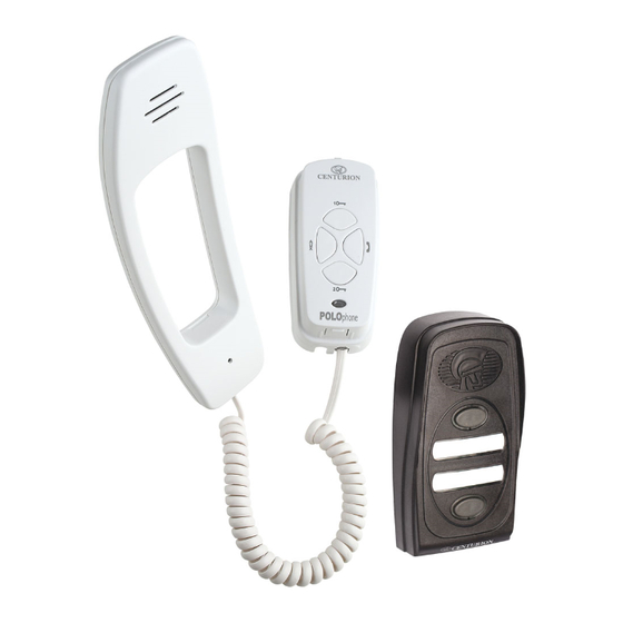
Centurion PoloPhone Installation Manual
Handset & entry panel(version 2)
Hide thumbs
Also See for PoloPhone:
- Installation manual (17 pages) ,
- Commissioning procedure (4 pages) ,
- Installation manual (17 pages)

Related Manuals for Centurion PoloPhone


Summary of Contents for Centurion PoloPhone
- Page 1 POL phone to have and to hold INSTALLATION MANUAL HANDSET & ENTRY PANEL(VERSION 2)
-
Page 2: Powering The System
The system uses a two wire bus to link all the components, making the wiring of the system particularly easy. Powering the system The Polophone system operates off a DC supply and can therefore be powered from either a 14V DC mains adaptor or directly from the battery supply of a 12V gate motor system. -
Page 3: Operation
Handset group on Entry Panel 1 Triggers the relay on Button “B” Closes the auxiliary Entry Panel 2 rings group contacts on the POL phone “B” handset(s) terminal block on the underside of the Handset Polophone Intercom - Page 3... -
Page 4: Specifications
Humidity IP Rating IP56 Surge Protection * NB: If 12V DC gate motor supply dips when motors starts up and the intercom is being used at the same time, the speech quality might be affected. Page 4 - Polophone Intercom... -
Page 5: System Components
SYSTEM COMPONENTS The POLOphone system is supplied as separate components: Component 1-Entry Panel (with one or two call buttons) consisting of: 2 X Mounting Screws 2 X Rawlplugs 1 X Mounting Screw sealing washer 1 X Cover Retaining Screw 2 X Call button labels... -
Page 6: Power Supply & Wiring
POWER SUPPLY & WIRING Power Supply The Polophone system operates off a 14V DC supply. The system is designed so that power can be connected to any one of the components in the system. If the system is being installed with a gate operator that can provide at least a 12V DC 150mA supply, the entry panel can be connected directly to this unit. - Page 7 NO and COM terminals together. For additional security it is advisable to wire to the auxiliary terminals on the handset or connect the PoloSwitch in the gate motor. Polophone Intercom - Page 7 Polophone Intercom - Page 7...
-
Page 8: Wall Mount Installation
‘sit’ on the wall without that it is vertical. Rocking. Rocking. Rocking. Mark the location of the mounting holes. Using a 6mm masonry bit, drill holes into the wall for the rawlplugs provided in the kit. Page 8 - Polophone Intercom... - Page 9 (See page 10). Clip outer cover back into position. Secure the cover using the fixing NB: It will be necessary when screw provided in kit. commissioning the unit to have the cover removed. Polophone Intercom - Page 9...
-
Page 10: Handset Installation
(A) - provided secure be perfectly vertical. the cable to the cradle base as shown. Page 10 - Polophone Intercom... - Page 11 ( ). similarly into the handpiece. Replace Insert the wire from the COM/- from the handpiece onto the cradle. the gate motor into the terminal marked with a ( ). Polophone Intercom - Page 11...
- Page 12 Page 12 - Polophone Intercom...
-
Page 13: Check Functions
Polophone Intercom - Page 13 Polophone Intercom - Page 13 Polophone Intercom - Page 13... -
Page 14: Fault Finding Guide
Check coil cord connection. Check that correct group (A or B) is selected on Handset. No speech when Increase volume on Handset. handset lifted Check coil cord connection to cradle. Check hook switch is free to move. Page 14 - Polophone Intercom... - Page 15 NOTES Polophone Intercom - Page 15...
- Page 16 Centurion Systems (Pty) Ltd Head Office: Tel: +27 (0)11 699-2400, Fax: +27 (0)11 704-3412 or 462-6669 148 Epsom Avenue, North Riding P.o. Box 506, Cramerview, 2060 South Africa Sharecall 0860-CENTURION (Sharecall number applicable when dialed from within South Africa only) or visit www.centsys.co.za...
Need help?
Do you have a question about the PoloPhone and is the answer not in the manual?
Questions and answers
Bell rings inside house and voice can be heard at gate but not in house. Unit is POLOphone and about 16 years old