Advertisement
Installer's Guide
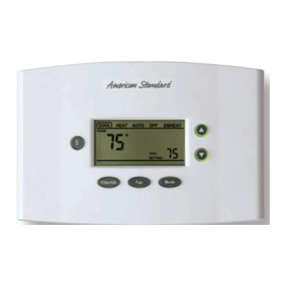
Premium
ACONT402AN32DA
3 Heat (Gas, Oil* or Elec) / 2 Cool / Heat Pump, Dual
Fuel
(Factory set for 2H/2C gas/cooling applications, BK Output enabled)
Electronic Non-Programmable
3 - 16 Wire Hookup (2 for Outdoor Sensor)
(2 for Optional Remote Indoor Sensor, 2 for Optional Humidistat)
ALL phases of this installation must comply with NATIONAL, STATE AND LOCAL CODES
Note: Read the entire instruction manual before starting the
installation.
Contents
Introduction ......................................................................... 1
Application .......................................................................... 1
Product Specifications ....................................................... 2
Installation ........................................................................... 2
Mounting and Wiring ........................................................... 2
SETUP ................................................................................. 3
Checkout ............................................................................. 4
Troubleshooting .................................................................. 12
Features .............................................................................. 13
Introduction
ACONT402AN32DA is a digital non-programmable 3Heat/ 2
Cool/Heat Pump/ Heat-Cool wall mounted low voltage
(24VAC) Comfort Control with backlit LCD and keypad. It
maintains room temperature by controlling the operation of
heating, cooling, heat pump and dual fuel systems. The
Comfort Control is easily configured for heat pump or cooling
only and gas or electric or dual fuel heat applications via the
user friendly Installer Setup menu. The Comfort Control
features include separate heating and cooling setpoints,
selectable auto or manual changeover, adjustable energy
saving mode, adjustable filter reminder, outdoor temperature
sensing, remote room sensing and remote humidistat input.
Setup selections and diagnostics are stored indefinitely in the
Comfort Controls nonvolatile memory eliminating the need
for battery backup.
Safety Considerations
Read the following manufacturer instructions carefully.
Follow all local codes during installation. All wiring must
conform to local and national electrical codes. Improper wiring
or installation may damage the comfort control.
Recognize safety information. This is the safety alert symbol
▲
!
. When you see this symbol on the equipment and in the
instruction manual, be alert to the potential for personal
injury.
Understand the signal words DANGER, WARNING and
CAUTION. These words are used with the safety-alert
symbol. DANGER identifies the most serious hazards which
will result in severe personal injury or death. WARNING
signifies a hazard which could result in personal injury or
death. CAUTION is used to identify unsafe practices which
could result in minor personal injury or product and property
damage.
$
Filter/OD
Application Hook Up Diagrams
Dual Fuel*
1-2 Stage/Step Heat Pump 2 Stage VS Gas Furnace
2 Stage Heat Pump
2 Stage VS Gas Furnace
2 Step Heat Pump
2 Stage VS Gas Furnace
1 Stage Heat Pump
2 Stage VS Gas Furnace
1 Stage Heat Pump
1-2 Stage Gas Furnace
Heat Pump
1-2 Stage/Step Heat Pump VS Air Handler
2 Stage Heat Pump
VS Air Handler
2 Step Heat Pump
VS Air Handler
2 Heat Pumps
Split Coil VS Air Handler
2 Heat Pumps
Split Coil VS Air Handler
1 Stage Heat Pump
VS Air Handler
1 Stage Heat Pump
Air Handler
Cooling
1-2 Stage/Step Cooling
VS Indoor
2 Stage Cooling
VS Indoor
2 Step Cooling
VS Indoor
2 Cool Units
Split Coil VS Air Handler
2 Cool Units
Split Coil VS Air Handler
1 Stage Cooling
VS Indoor
1 Stage Cooling
non-VS Indoor
1 Stage Cooling
1 Stage Oil Furnace
* Requires external relay for Oil furnace applications. TAYPLUS103 not
required
BAYSENS01ATEMPA for outdoor temperature sensing and display and
optional control is included.
Optional Humidistat: ASYSTAT625A
Optional Remote Indoor Sensor: ZZSENSAL0400AA
11-HD03D3-3
Fan
Mode
w/ BK
no BK
no BK
no BK
no BK
w/ BK
no BK
no BK
w/ BK
no BK
no BK
no BK
w/ BK
no BK
no BK
w/ BK
no BK
no BK
no BK
no BK
FIG
DF-1
DF-2
DF-3
DF-4
DF-5
HP-1
HP-4
HP-5
HP-2
HP-3
HP-6
HP-7
CL-1
CL-3
CL-4
CL-2
CL-5
CL-6
CL-7
OIL-1
Advertisement

Related Manuals for American Standard ACONT402AN32DA


Summary of Contents for American Standard ACONT402AN32DA
-
Page 1: Table Of Contents
Mode Troubleshooting ..............12 Filter/OD Features ................13 Introduction ACONT402AN32DA is a digital non-programmable 3Heat/ 2 Application Hook Up Diagrams Cool/Heat Pump/ Heat-Cool wall mounted low voltage Dual Fuel* (24VAC) Comfort Control with backlit LCD and keypad. It maintains room temperature by controlling the operation of... -
Page 2: Product Specifications
2. If an existing thermostat is being replaced: only 1/4-in. of insulation from each wire to prevent a. Remove existing thermostat from wall. adjacent wires from shorting together when connected. © 2007 American Standard Inc. All Rights Reserved Pub. No. 11-HD03D3-3... -
Page 3: Setup
Installer’s Guide 8. Match and connect control wires to proper terminals on the SETUP connector block. (See the following wire diagrams). Enter INSTALLER Setup: 9. Push any excess wire back into the wall and seal the hole to prevent air leaks. (See Table 3, step 1 - 49 for option details) 1.) Set System Mode to OFF Note: Air leaks in the wall behind the control can cause... -
Page 4: Checkout
Installer’s Guide Table 1 Manual Test Mode Press Fan to return to the previous step. Setting (Choices) Use the Up and Down arrow buttons to select or change Menu Item Step Default (Press Up or Down setup options. (Press Mode or Fan) (Press Mode or Fan) Arrow) "6"... - Page 5 Installer’s Guide DUAL FUEL ONE OR TWO STAGE OR TWO STEP HEAT PUMP DUAL FUEL TWO STAGE HEAT PUMP TWO STAGE VS GAS FURNACE TWO STAGE VS GAS FURNACE BK ENABLED BK DISABLED Note B - Cut/remove the factory installed "BK" jumper at the indoor unit. Note C - For Dual Fuel, cut the JP1 jumper on the Comfort Control.
- Page 6 Installer’s Guide DUAL FUEL SINGLE STAGE HEAT PUMP NON-VARIABLE SPEED GAS FURNACE BK DISABLED Note C - For Dual Fuel, cut the JP1 jumper on the Comfort Control. NOTE: See Fig. OIL-1 for external relay connections for oil furnaces. COMFORT CONTROL NON-V.S.
- Page 7 Installer’s Guide ONE OR TWO STAGE OR TWO STEP HEAT PUMP TWO HEAT PUMPS VARIABLE SPEED AIR HANDLER SPLIT COIL VARIABLE SPEED AIR HANDLER BK ENABLED BK ENABLED Note B - Cut/remove the factory installed "BK" jumper at the indoor unit. Note B - Cut/remove the factory installed "BK"...
- Page 8 Installer’s Guide TWO STAGE HEAT PUMP TWO STEP HEAT PUMP VARIABLE SPEED AIR HANDLER VARIABLE SPEED AIR HANDLER BK DISABLED BK DISABLED Note A - The installer must jumper "R" to "O" at the LVTB. Note B - Cut/remove the factory installed "BK" jumper at the indoor unit. VARIABLE SPEED TWO STAGE AIR HANDLER &...
- Page 9 Installer’s Guide ONE OR TWO STAGE OR TWO STEP COOLING VARIABLE SPEED INDOOR BK ENABLED Note B - Cut/remove the factory installed "BK" jumper at the indoor unit. Note B - Cut/remove the factory installed "BK" jumper at the indoor unit. NOTE: See Fig.
- Page 10 Installer’s Guide TWO STAGE COOLING SINGLE STAGE COOLING SPLIT COIL VARIABLE SPEED AIR HANDLER VARIABLE SPEED INDOOR BK DISABLED BK DISABLED NOTE: Two additional wires are required for Outdoor Temperature Sensor. NOTE: See Fig. OIL-1 for external relay connections for oil furnaces. NOTE: Two additional wires are required for Outdoor Temperature Sensor.
- Page 11 Installer’s Guide 2nd Stage Compressor Table 3 INSTALLER SETUP (ISU) 2 - 6 CPH *see notes at the bottom of setup (ISU) Table 3A Heating Cycles Per Hour 1. Set System MODE to OFF 2nd Stage Compressor Heating 1 - 15 Minutes 2.
- Page 12 Installer’s Guide TABLE 3A USER SETUP (USU) Press and hold MODE and FAN at the same time. Menu Item Default Setting (Choices) Step (Press UP or DOWN arrow) (Press Mode or Fan) Temperature Display 0=Fahrenheit,1=Celsius Auto or Manual Changeover 0=Manual,1=Auto Setpoint Deadband 2 - 10 Degrees Fahrenheit 1.5 - 5.0 Degrees Celsius...
-
Page 13: Troubleshooting
Installer’s Guide Table 4 Troubleshooting Symptom Possible Cause Action 1. Blown fuse or tripped circuit breaker. 1. Replace fuse or reset breaker. 2. Furnace power switch OFF. 2. Turn switch to ON. Display will not come on. 3. Furnace blower compartment door or panel 3. -
Page 14: Features
Installer’s Guide Features Cooling Efficiency Booster - (Single Stage Compressor BK Output Only) - BK Enabled With the BK Output enabled (the factory default) the The indoor air flow is reduced to 80% at outdoor Comfort Control sends a Pulse Width Modulated (PWM) temperatures below 87°F in cooling mode. - Page 15 Installer’s Guide Wait Indicator “Waiting” will illuminate when the indoor setpoint is The Energy Savings mode is activated by pressing the moved in the direction of calling for additional system Energy Savings key “$” on the control’s keypad. Pressing capacity. “Waiting” indicates system time delays are being the Energy Savings key “$”...
- Page 16 Installer’s Guide Reduces the indoor air flow to 80% when the room RESTRICTED MODE - (Requires Outdoor temperature is within 2 degrees of the setpoint Temperature Sensor) and when the room temperature is below the The Heat Pump Restricted Mode Outdoor Temperature setpoint.
- Page 17 Installer’s Guide Pub. No. 11-HD03D3-3...
- Page 18 American Standard Inc. 6200 Troup Highway Tyler, TX 75707 Since the manufacturer has a policy of continuous product and product data improvement, it reserves the right For more information contact your local dealer (distributor) to change design and specifications without notice.
Need help?
Do you have a question about the ACONT402AN32DA and is the answer not in the manual?
Questions and answers
What is the flashing “waiting” mean?
The flashing "Waiting" indicator on the American Standard ACONT402AN32DA means the system is enforcing time delays and adjusting to a new setpoint after the indoor temperature setpoint has been changed in a way that calls for more system capacity.
This answer is automatically generated